This thread has been locked.

If you have a related question, please click the "Ask a related question" button in the top right corner. The newly created question will be automatically linked to this question.

Is force_angle automatically disabled when flux frequency is above USER_FORCE_ANGLE_FREQ_Hz

Other Parts Discussed in Thread: MOTORWARE

I enable the force_angle to help the motor to start rotation with a heavy load. But some times the force_angle_status keeps 1 so that the motor couldn't accelerate to its set speed. (it rotates very slow, around the force_angle_freq_hz)

I find the Force_Angle_status to be 1, therefore, the controller used forced angle information but not est angle. 

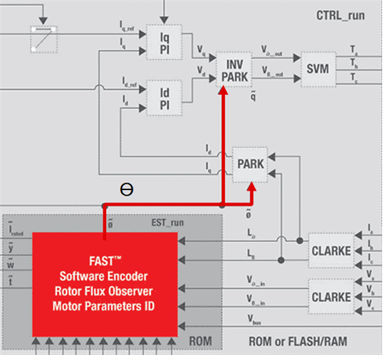
The force_angle should be disabled automatically after FAST est angle estimation converges to let FAST est angle take over the angle input to the PARK/CLARK conversion. 

Is that correct? If so, what should I be aware to solve this problem?

Thank you.

  • Jinku Hu said:

    If ForceAngle is Enabled

    {

    if estimated speed is > USER_IQ_FULL_SCALE_FREQ_Hz * USER_ZEROSPEEDLIMIT

           then FAST Angle will be used to feed the forward control loop

    if estimated speed is < USER_IQ_FULL_SCALE_FREQ_Hz * USER_ZEROSPEEDLIMIT

           then Angle from the ForceAngle function will be used to feed the forward control loop


    Jinku Hu said:

    I enable the force_angle to help the motor to start rotation with a heavy load.

    This isn't always the best solution. The ForceAngle feature isn't mean to be a rotor sensor at slow speed. It is meant to generate a stable estimated angle to move the rotor from zero/low speed into an area of stable FAST estimator operation.  It is most useful to be used to generate a stable angle signal, that rotates at a known rate, when FAST is not providing a good one.

    Jinku Hu said:
    But some times the force_angle_status keeps 1 so that the motor couldn't accelerate to its set speed. (it rotates very slow, around the force_angle_freq_hz

    the ForceAngle Flag will always keep 1 if it is set at 1 and is not set by the user to 0.

    Regarding the status, you can see the logic used

     if(_IQabs(fe_pu) < _IQ(USER_ZEROSPEEDLIMIT))
       {
         is_forced_angle_active = true;
       }
    else
       {
         is_forced_angle_active = false;
       }

    It is only active if "fe_pu" is below the limit.  You may think you are over the limit, but FAST may not....because it does not have good enough feedback signals yet.  Try raising your limit some more.


    Jinku Hu said:

    The force_angle should be disabled automatically after FAST est angle estimation converges to let FAST est angle take over the angle input to the PARK/CLARK conversion. 

    Yes, per the logic in the first response to this thread.

    Jinku Hu said:
    If so, what should I be aware to solve this problem?

    One thing that isn't documented very well is that you should insure

    USER_FORCE_ANGLE_FREQ_Hz >= 2 * USER_IQ_FULL_SCALE_FREQ_Hz * USER_ZEROSPEEDLIMIT

    - This makes sure that the frequency of the ForceAngle is at a speed greater than the switch over frequency, that you don't get caught below this rate. For example, the default for FORCE_ANGLE is (1.0), so that's the maximum rate used for the ForceAngle feedback to increment the fake estimated feedback angle.

    But what if you have tested your motor and decided that you have solid estimation from FAST at 3 Hz, so you set

     USER_IQ_FULL_SCALE_FREQ_Hz * USER_ZEROSPEEDLIMIT = 3 Hz

    When you start up to say a 10 Hz speed command with ForceAngle enabled, the ForceAngle feature creates an angle feedback to the system that emulates a 1 Hz rotation.

    What happens between 1 Hz and 3 Hz?

    Force Angle is still using a 1 Hz rotation, while the rest of the control system is commanding torque to try to get to 10 Hz.  So between 1 Hz and 3 Hz the angle being used will be "incorrect".  The ForceAngle is emulating a rotor moving at 1 Hz, while in actuality the rotor is moving at for example 1.3 Hz, then 1.6 Hz, then 2.2 Hz, etc.

    and the slower you accelerate the worse it will be....and you introduce some level of instability and less than full torque.

    Please see chapter 15 of SPRUHJ1 for some helpful information regarded loaded start. 

  • Hello Chris,

    Thank you very much for your detailed answer.

    I've tried with your suggestion, but the problem still exists. The motor couldn't start up everytime, and the speed it rotates doesn't even follow the force angle frequeny you set. The speed of the motor when it couldn't start up is around 20 RPM no matter the force angle frequency is 1 Hz or 5 Hz.

    Does it related with CCS and complier version? (see http://e2e.ti.com/support/microcontrollers/c2000/f/902/t/295599.aspx)

    I use CCS Version: 5.4.0.00091 and complier v6.0.6

    By the way, we make our own hardware but the core codes of Instaspin is definitely the same with TI example projects.

  • I don't know of any bug in 6.0.6, but we never tested below 6.1.5 and we recommend using latest 6.2.3+

    Jinku Hu said:

    I've tried with your suggestion, but the problem still exists. The motor couldn't start up everytime, and the speed it rotates doesn't even follow the force angle frequeny you set. The speed of the motor when it couldn't start up is around 20 RPM no matter the force angle frequency is 1 Hz or 5 Hz.

    The speed it will try to rotate at is not the ForceAngle frequency. The motor is still attempting to be controlled by the forward control system, which is your speed or torque controller.  ForceAngle (just like FAST) only feeds the Angle feedback into the iPARK module.  ForceAngle is incrementing this angle as if it was rotating at USER_FORCE_ANGLE_FREQ_Hz

    If your controller is trying to regulate the motor at 20 RPM, I'd guess you were commanding 20 RPM, or the PI control system isn't tuned well enough for stability.

    The point of ForceAngle is to get you from zero / low speed into an area where FAST feedback is accurate and can be used in the control system reliably.


  • Hello Chris,

    After some tests, I think I'm quite close to the root cause of this problem.

    What I notice is if I reduce the Maxacceleration from 2 to 0.5 kRPM, the motor could start up every time.

    But I'm curious whether the Maxacceleration has so large influence on your motor start up (even we test under no load)? Is it easy to explain? Or how should I tune my speed control loop Kp, Ki for a better startup performance (still, motor sometimes couldn't start up without any load)?

  • What speed are you trying to start up to? When at that speed is everything stable?

    I've seen issue like you describe that are caused by the speed loop tuning. Sometimes a better tuning for this startup helps (and using SpinTAC helps). Another thing that helps is an initial alignment with RsRecalc or some +Id_Ref_A. And yet another solution that seems to always work is to remove the speed loop entirely and start up in Torque mode, and feed the torque input from a trajectory module to ramp the input (just like controlling how hard you press the pedal in your car) until the speed hits your target, then switch on your speed loop, with its output seeded to the Iq input. 

  • Hello Chris,

    I think now I got the answer. It's because of zerospeedlimit setting. When I both increase zerospeedlimit and force_angle, and meanwhile keep force_angle twice of zerospeedlimit, the motor could startup every time.

    But the settings for zerospeedlimit is pcb-denpendent. Some boards use 3Hz and some use 5Hz.

    Is there any tutorial to explain how to choose the correct zerospeedlimit?

    Thanks.

  • Jinku Hu said:

    But the settings for zerospeedlimit is pcb-denpendent. Some boards use 3Hz and some use 5Hz.

    Why are they PCB dependent?  You mean because USER_ZEROSPEEDLIMIT gets multiplied by USER_IQ_FULL_SCALE_FREQ_Hz to set the limit frequency, and some of your boards use different FULL_SCALE_FREQ?

    If you want the result of USER_IQ_FULL_SCALE_FREQ_Hz * USER_ZEROSPEEDLIMIT to be fixed regardless of USER_IQ_FULL_SCALE_FREQ_Hz just use

    #define USER_ZEROSPEEDLIMIT   (1.0 / USER_IQ_FULL_SCALE_FREQ_Hz)

    This is what I do in my user.h anyways. That way when I change USER_IQ_FULL_SCALE_FREQ_Hz during testing of all sorts of motors I don't have to go update the ZEROSPEEDLIMIT, it will always be set to 1.0 Hz, regardless of USER_IQ_FULL_SCALE_FREQ_Hz.

    I also go ahead and use

    #define USER_FORCE_ANGLE_FREQ_Hz            (2.0*USER_ZEROSPEEDLIMIT*USER_IQ_FULL_SCALE_FREQ_Hz) 

    so that the ForceAngle Freq is always 2* the effective ZEROSPEEDLIMIT

    Jinku Hu said:

    Is there any tutorial to explain how to choose the correct zerospeedlimit?

    What you did is exactly correct if you want to use ForceAngle. You want to choose a lower limit depending on the flux measurement of your motor and sense resolution.

    What values worked well for your motor?  What is the Flux_VpHz of your motor?  What is your ADC_VOLTAGE scaled to?


  • Hi Chris,

    I failed to understand something - does USER_MAX_ACCEL_Hzps has anything to do with ForceAngle ?

    When ForceAngle is active, is the frequency of the angle change is fixed (for example, 5 hz), or is it ramped to 5 hz ?

    Where and by whom USER_MAX_ACCEL_Hzps is used ? Since it does not appear anywhere in the code (except for setting in user_vars) it's a bit obscure to us...

    Thanks a lot

  • Mojo said:

    I failed to understand something - does USER_MAX_ACCEL_Hzps has anything to do with ForceAngle ?

    Not directly, no. 

    Mojo said:

    When ForceAngle is active, is the frequency of the angle change is fixed (for example, 5 hz), or is it ramped to 5 hz ?

    Yes, the angle generated from ForceAngle is based on a starting angle of 0 and then an increment based on the USER_FORCE_ANGLE_FREQ_Hz per every CTRL frequency update.  It emulates a rotor turning at USER_FORCE_ANGLE_FREQ_Hz.

    Mojo said:
    Where and by whom USER_MAX_ACCEL_Hzps is used ?

    This just sets the default acceleration of the Trajectory module used with the speed controller. In proj_lab05b you run in speed mode and use the Trajectory module to feed the Speed PI. You can change the acceleration using a variable we bring out to the gMotorVars structure

    gMotorVars.MaxAccel_krpmps

    You can see in proj_lab05b.c that we use this user variable to set the acceleration into the control system

                // set the speed acceleration
                CTRL_setMaxAccel_pu(ctrlHandle,_IQmpy(MAX_ACCEL_KRPMPS_SF,gMotorVars.MaxAccel_krpmps));


  • I use the same USER_IQ_FULL_SCALE_FREQ_Hz for all boards.

    Some boards use USER_ZEROSPEEDLIMIT (3.0 / USER_IQ_FULL_SCALE_FREQ_Hz) to start up motor sucesfully every tiime, and some boards have to increase it to (5.0 / USER_IQ_FULL_SCALE_FREQ_Hz). That's why I found it board-dependent.

    ChrisClearman said:

    What is the Flux_VpHz of your motor?  What is your ADC_VOLTAGE scaled to?

    The flux is 0.03520443.

    ADC_FULL_SCALE_VOLGAGE_V is 67.5V, but IQ_FULL_SCALE_VOLTAGE_V is 15V as the power supply is 12V. 

    I know it's not good and will modify the voltage sensing circuits in the next version.


  • with better voltage scaling I expect you will be able to use a Force_Angle Freq of about 2 Hz.

    With what you are doing now, I suspect that the motors that startup with 3 Hz will also start-up with 5 Hz, so I would use the higher value.


  • You are right, 5 Hz also suits for 3 Hz condition.

    Anyway, is there a method to determine this zerospeedlimit?

  • I use JTAG to watch the noises of 12-Bit ADC to find out that there's only 1 or 2 bit noises when motor keeps still (ctrl is enabled).

    Is the zerospeedlimit related with your ADC nosie level, something like you should keep motor back-EMF at the speed of zerospeedlimit at least 4 (or other numbers) times than nosie level on ADC?

  • Hi Chris,

    ChrisClearman said:
    Force Angle is still using a 1 Hz rotation, while the rest of the control system is commanding torque to try to get to 10 Hz.  So between 1 Hz and 3 Hz the angle being used will be "incorrect".  The ForceAngle is emulating a rotor moving at 1 Hz, while in actuality the rotor is moving at for example 1.3 Hz, then 1.6 Hz, then 2.2 Hz, etc.

    I confused about if I define  ForceAngle is 2 Hz . according to what you said ForceAngle can emulate a rotor moving at 2 Hz . my question is if ForceAngle also can emulate a rotor moving at 0.5Hz  0.8Hz  1 Hz  and  1.5Hz ?In other words, the ForceAngle only can emulate what it define ?

  • Correct,

    Force Angle Frequency / control frequency = increment to add to the angle

    Think of it like a fixed acceleration for a trajectory module of your speed controller.  It's doing the same thing accept with the angle.

    If you want to accelerate from 0 to 1000 RPM in 10 seconds, with a fixed acceleration that's100 RPM/sec.

    If your speed controller gets executed every 1 KHz = 1ms then you will have 10 sec / 1ms = 10,000 speed control updates in this movement.

    1000 RPM / 10,000 updates = 0.1 RPM increments

    So what your Trajectory generator is sending to your Speed Controller Reference is a series of speeds, starting at 0 RPM, with an increment of 0.1 RPM each control cycle..

    0, 0+0.1, 0.1+0.1, 0.2+0.1....999.9+0.1, 1000.0 RPM

    (of course, everything is actually done in per unit, but this makes it easeier to conceptualize).

    Force Angle does the same thing, it creates this series of Angle references based on the frequency you set and the control update rate

    1 Hz = 1 rev / sec = 2pi rad/sec

    if you run your control system at 10 kHz, you would have an increment of 2p/i10,000 radians.

    If you want to think of it in degrees, it would be like an increment of 0.036 degrees every control update.

    This new angle is being used as the estimated angle to drive the the control system until FAST is allowed to take over.


    When we release our IPD solutions we will show that in most cases you don't want to use ForceAngle any longer.  You get the initial angle, set this as your starting angle, and then let FAST start providing the new angle immediately.


    Make sense now?


  • Jinku Hu said:

    Is the zerospeedlimit related with your ADC nosie level, something like you should keep motor back-EMF at the speed of zerospeedlimit at least 4 (or other numbers) times than nosie level on ADC?

    It certainly is related to your Bemf produced (Flux * Frequency).  But  we don't have a specific formula you can use, it's more trial and error at this point.  We are doing some testing though and I'll add this to the list of things we would like to provide data on.


  • hello,when I set USER_FORCE_ANGLE_FREQ_Hz(such as 0.1)  is much smaller than  (USER_ZEROSPEEDLIMIT * USER_IQ_FULL_SCALE_FREQ_Hz )(which is 0.8*300),  that means force angle frequency will not get to USR_ZEROSPEEDLIMIT , in this case , the return  value of EST_getForceAngleStatus will always be set 1.Is it right?

    but when  i read back the value of  EST_getForceAngleStatus,at first it returns 1,then it returns 0.which means it pass

    the stage of Force angle,and at the stage of online. i feel confused?

  • how can I get your IPD solution?

  • simpson bart said:

    how can I get your IPD solution?

    We will release IPD solutions in MotorWare when they are ready for public consumption.  We are working on making these easy to use.

    simpson bart said:
    hello,when I set USER_FORCE_ANGLE_FREQ_Hz(such as 0.1)  is much smaller than  (USER_ZEROSPEEDLIMIT * USER_IQ_FULL_SCALE_FREQ_Hz )(which is 0.8*300),

    Don't do this.  keep the FORCE_ANGLE_FREQ > 2 * (USER_ZEROSPEEDLIMIT * USER_IQ_FULL_SCALE_FREQ_Hz )

    simpson bart said:
    the return  value of EST_getForceAngleStatus will always be set 1.Is it right?

    No.  If ForceAngle is kept enabled, as soon as the estimated rotor frequency is > 0.8 * 300 Hz the ForceAngleStatus will turn to 0.

  • Dear ChrisClearman:

    Sorry for bothering you again.At this time,when I was doing experiment,it was alright  when output in low frequency.However When speed up the motor (above 4500 ramp/min),something was wrong with my control system for my driver chip is not worked which is caused by PWM Death Region.Do you know how to control PWM to avoid PWM Death Region which two triode is both opened and damaged the chip.Or do you have ideas where I can set the PWM Death Region parameter to avoid this situation.

                                                                                                                                                                Thank you for reading

  • I'm not sure what you mean. 

    The PWM driver in our examples are setup to guarantee the driver has appropriate Deadtime so that high and low side of a switch are not on at same time. You can adjust these settings for your own inverter. 

    But you also mentioned control problems when accelerating. This is common with PI based speed controllers. The gains for stiff control are too aggressive at higher speeds, so they must be reduced.   This is called gain scheduling or staging. Another solution is to use SpinTAC in InstaSPIN - MOTION which typically only needs one gain. 

  •  Can you list some of settings which is involved in Deadtime for I have no ideas about setting Deadtime parameter.

  • My driver MCU is likely  to be damaged while accelerating the motor (above 300hz output)when in work-load condition,however this situation is never happened when in no-load condition. What's more,My driver MCU is bad

    for high current flow into which is controlled by PWM.

  • I note there is the sentence which refer to PI control:"The SpinTAC speed controller also features a single tuning parameter, bandwidth, which determines the stiffness of the system and dictates how aggressively the system will reject disturbances. This single parameter makes it very easy to adjust the tuning of the SpinTAC speed controller."in usr manual.

    So how Can I modify the parameter in USER.h to adjust bandwidth.


  • Please follow instaspin_labs.pdf for instaspin_motion labs starting at lab05c. This walks you through inertia/friction ID, tuning, and saving that value in user.h. 

  • Dear Chris,

    I update the driver MCU's reference manual,and I was gratitude if you give me some advice to modify parameter.

      the drv.h parameter :

     #define DRV_PWM_DBFED_CNT         (uint16_t)(2.0 * (float_t)USER_SYSTEM_FREQ_MHz)            // 2 usec

    #define DRV_PWM_DBRED_CNT        (uint16_t)(2.0 * (float_t)USER_SYSTEM_FREQ_MHz)            // 2 usec

    this parameter is set to delay the deadtime .

    This is my driver MCU's reference manual.  How do I modify the parameter in drv.h

    5383.FSBB30CH60C.pdf 

  • your driver datasheet says

    tdead Blanking Time for Preventing

    Arm-short

    For Each Input Signal 2.0 - - μs


    and that is exactly what you are setting for both rising and falling edge dead-band.  This is the minimum though, so maybe you want to increase it a bit.


    If you are having issues I would look first at the parameter ID to make sure it makes sense...if the Ls value is quite off it will effect your current control capability, especially as you try to increase speed. It will become unstable and that's where something could trip / get damaged.


  • Hi Chis:

          I'm colleague of . Our problem is that when we run the motor around 4500rpm, all thing seem right. but randomly, our DC power system is protected for short circuit. And we found that our driver is damaged, one couple of the high/low side IGBTs is shorted. The max output current we set is "#define USER_MOTOR_MAX_CURRENT          (20.0)". less than driver's max current 30A.  Before the problem happen, running condition is: output voltage is about 220V, and the feedback current is about 11A, and the DC bus voltage is about 310V. All seems right, but randomly the driver will crash. We found 4 times when the speed is above 4000rpm, but we haven't saw under 4000rpm with load or 0-8000rpm without load yet. (Out product is aircondition) .

     The following is IDed motor params    

    #define USER_MOTOR_Rs                          (0.3718042)
    #define USER_MOTOR_Ls_d                      (0.001489422)
    #define USER_MOTOR_Ls_q                      (0.001489422)
    #define USER_MOTOR_RATED_FLUX      (0.2737856)

    the driver PWM Deadtime we set is 2us, which matchs the driver's spec.

     What's your suggestion about this problem? 

    Thanks!

    Ben

  • 1. Please attach your full user.h

    2. 310v is your normal bus voltage? 

    3. Have you monitored your current using a current probe?

    4. Have you tried running lab05b? This will take the speed loop stability out of the equation. So the motor doesn't go to full maximum speed you can limit the max Vs ins user.h. Default is (1.0) so start with. 0.3 and raise until you get to / past the problem speed. 

  • 1. Attachment is the user.h we current used.

    3683.user.h

    2. Yes, our normal DC bus voltage is 310v.

    3. We havn't monitor the current using a current probe. We just display the value from board to PC, and display it.

    4. We will try that, our motor designed max speed is 8000rpm, it seems that the problem occurs randomly above 4000rpm. We will try to limit the Vs first, and try again. 

  • Hi Chris:

        When I review the user.h, I found that USER_IQ_FULL_SCALE_FREQ_Hz may be wrong. 300Hz is the value which we test on 15V DC Bus. We'll altered to 800Hz, and try again. Maybe it is the problem causes the driver damage, because the speed around 4500 will cause calclation overflow if max speed is set to 4500.

    Ben

  • Minjian Zhang1 said:
    300Hz is the value which we test on 15V DC Bus.

    15V bus?  That is extremely low for your HV inverter.

    Also, with a flux of 0.27 V/Hz, you will create more voltage than the bus @ 15V / 0.27 V/Hz = 55.5 Hz

    With 8 poles that is 833 RPM maximum

    This is completely wrong. You can't change your ADC scaling just based on the bus voltage. The ADC scaling is FIXED by your hardware sense circuitry.

    #ifdef DC_BUS_15V
    #define USER_ADC_FULL_SCALE_VOLTAGE_V (25.8) // 409.6 hvkit_rev1p1 voltage scaling
    #else
    #define USER_ADC_FULL_SCALE_VOLTAGE_V (409.4538) // 409.6 hvkit_rev1p1 voltage scaling
    #endif

    #ifdef DC_BUS_15V
    #define USER_ADC_FULL_SCALE_CURRENT_A (22.0) // (33.0)
    #else
    #define USER_ADC_FULL_SCALE_CURRENT_A (66.0) // (33.0)
    #endif

    #ifdef DC_BUS_15V
    #define USER_VOLTAGE_FILTER_POLE_Hz (829.5) // 372.5, value for hvkit_rev1p1 hardware
    //#define USER_VOLTAGE_FILTER_POLE_Hz (1764.968) // 372.5, value for hvkit_rev1p1 hardware
    #else
    #define USER_VOLTAGE_FILTER_POLE_Hz (375.1416) // 372.5, value for hvkit_rev1p1 hardware
    #endif

    these statements tell the software that you have completely different hardware.

    Minjian Zhang1 said:
    300Hz is the value which we test on 15V DC Bus. We'll altered to 800Hz, and try again. Maybe it is the problem causes the driver damage, because the speed around 4500 will cause calclation overflow if max speed is set to 4500.

    300 Hz is 4500 RPM with your 8 poles, but with InstaSPIN-FOC this won't limit you directly. It allows speed estimations and references up to 1.99* the max frequency, so nearly 9000 RPM before variable roll-over.

    back to your HW....your design is identical to our HVKIT except you have 33A capable current?  Is that correct? That's what your user.h states.

    Assuming your HW is correct, everything in user.h looks ok for My_Motor_10_mO as long as you are NOT using the 15V IFDEF and you set the IQ_FREQUENCY to (800.0) as you noted.

  • Hi Chirs:

        Thanks for you reply.

        15V DS bus is just for test, and the current sensor circuit is different. We are sure the setting is correct, we are use 15V to test the software correntness to avoid destroy hardware. 15V is extremely low, but it just can work for testing purpose. You can just ignore it's setting.

        As you say, the speed can reach1.99 * max freq without overflow, so that our previous setting seems not cause the problem around 4500-5000 rpm. but it has happened, we haven't find out the reason yet.

        Yes, we designed the current channel's capablity of 33A. Our driver's current capablity is 30A, we will limit the current output about 20A. Out current sensor res is 10mO, and amplification factor is five. so the max current we can sample is 66A (+-33A). Is there any problem? 

    Ben

  • looking at your parameters, I think your inductance is not low enough.

    Rs / Ls = 0.286 / 0.0017 = 168 Hz; I would expect a value closer to 800-1KHz, which means Ls < ~350uH

    and Flux / 2pi / Ls = 25A, I would expect about double for a 20A motor, which means Ls < 650uH

    a widely incorrect inductance will give you incorrect angle estimation and get worse at higher speed.

    1. Is your motor spinning during the entire portion of ID from RampUp until ID is finished?

    2. Increase USER_MOTOR_FLUX_EST_FREQ_Hz to (50.0)

    3. Try a bit more USER_MOTOR_IND_EST_CURRENT

    see if you get a different Ls value

    after that, try proj_lab05b to take the speed loop out of the equation....but I'm pretty sure it is your Ls value that is causing the problem.

  • Hi,Chris

         Thanks for your reply.  I am subordinate to ben. I did the experiment twice,and observed every state in motor configuration. I notice that when I did the motor configuration(which set 15 seconds  in RampUp state),there is two different result (the first 5 to 10 seconds the motor is  spinning normal ,but after 10 seconds the motor is not spinning ),which I wonder if it is alright  when doing motor configuration experiment. From  RatedFlux_OL until ID is finished,the motor is spinning.

    there are the result of Rs and Ls .

    1.we define  USER_MOTOR_FLUX_EST_FREQ_Hz  (50.0);USER_MOTOR_IND_EST_CURRENT(1.5);

    get the Rs is (0.2381253).Ls(0.001679824).

    2.we define USER_MOTOR_FLUX_EST_FREQ_Hz  (50.0);USER_MOTOR_IND_EST_CURRENT(2.0);

    get the Rs (0.2586821).Ls(0.001637632).

    Rs / Ls which  is approximately equal to the former ID identify(which you mentioned 168hz).


    On Friday, we hit the problem again.And the waveform of Iq reference,Id reference,and speed reference are presented in the attached file.

    0116.Problem.doc

  • Motor must continue rotating at the target speed from RampUp until RampDown. Your flux and Ls values are incorrect. 

    Are you using proj_lab02c for ID? It sounds like the Rhf / Lhf for your motor is too large for our base library hence you need to use special 02c which includes re-scaling of variables. 

  • Dear Chris,

     I run the motor for ID by proj_lab02c ,And  got the value of Rs,Ls and Flux

    I list the result of my experiment. 

    1.

    #define USER_MOTOR_FLUX_EST_FREQ_Hz  (20.0)

    #define  USER_MOTOR_IND_EST_CURRENT  (-1.0)

    result:

    Ls_d  0.001597973

    Ls_q  0.001597973

    Rs  0.2866025

    Flux 0.273534

    2.

    #define USER_MOTOR_FLUX_EST_FREQ_Hz  (20.0)

    #define  USER_MOTOR_IND_EST_CURRENT  (-2.0)

    result:

    Ls_d  0.001590607

    Ls_q  0.001590607

    Rs  0.2858866

    Flux 0.2742202

    3.

    #define USER_MOTOR_FLUX_EST_FREQ_Hz  (50.0)

    #define  USER_MOTOR_IND_EST_CURRENT  (-2.0)

    result:

    Ls_d 0.001698911

    Ls_q 0.001698911

    Rs   0.2880002

    Flux 0.2743613

    you mentioned that the value of Rs/Ls expected be a value closer to 800-1khz,and the value of Flux / 2pi / Ls should be large as 50A. However,enlarging  the  USER_MOTOR_FLUX_EST_FREQ_Hz  or USER_MOTOR_IND_EST_CURRENT seems little help to  get the correct motor ID. 

     thanks for reading.


  • Well, everything points to this motor being much lower speed than you say it should be.  The ID results are very consistent.

    What bus voltage are you running during these tests?

    Have you ever run this motor at the speeds you claim?

  • Actually,I run these tests by the bus voltage 15V. Does this matter the result of ID configuration. I will do the experiment by the bus voltage 308V to see if the result changed.As for speed,if my target speed is 8000 ramp/min,

    how much speed do i need to run the ID configuration?

  • yes, certainly increase your bus voltage. You need enough voltage to hit the speed you set in user.h for flux identification.  I would use 50V minimum.

    make sure the motor spins continuously during RampUp until RampDown.

    make sure that at the end of RampUp state the Speed Estimate and Trajectory Reference are same / close.

  • Hi,Chris:

    Sorry for disturb you again.We increase the bus voltage to 308 V. We hit the speed which we set in user.h for flux identification.As a result, we get the speed of 750 ramp,and for the frequency is 50 HZ which is equal to  the estimate frequency( USER_MOTOR_FLUX_EST_FREQ_Hz (50.0)). The motor is spinning continuously during RampUp utill RampDown.But I am confused with Trajectory Reference,Which value in project do I need to monitor.

    Here is the result of our ID configurate  experiment.

    We change the USER_MOTOR_IND_EST_CURRENT from 1.5 to 3.0 (Est_current) ;USER_R_OVER_L_EST_FREQ_Hz(RL_Freq)from  100 HZ to 300 HZ  .

    Est_current RL_Freq Rs Ls_q Ls_d Flux
    1.5A 100HZ 0.34197 0.00164 0.00164 0.27390
    1.5A 150HZ 0.33242 0.00170 0.00170 0.27450
    1.5A 200HZ 0.30413 0.00167 0.00167 0.27422
    1.5A 250HZ 0.34802 0.00169 0.00169 0.27417
    1.5A 300HZ 0.34126 0.00163 0.00163 0.27349
    2.0A 300HZ 0.35961 0.00170 0.00170 0.27417
    2.5A 300HZ 0.32625 0.00174 0.00174 0.27447

    If it is the result of  motor's ID parameter.How much speed  this system runs safely, and what will happen if we set the speed above limited speed based on this type of motor? 

    I also upload the waveform of every state of ID configuration 

    2772.ID_Process.docx

  • once again, the parameters are consistent. I feel strongly that this motor is designed for no more than 300 Hz.

    using the default modulation of 1.0 I suspect you won't quite make 300 Hz (4500 RPM). To go faster you will need to increase the modulation (proj_lab10) and/or use field weakening (proj_lab09).

    Any instability seen (earlier in this posting) is most likely caused by improper tuning of the speed controller. If you haven't tuned, do so. At a minimum reduce the speed Kp from the default value and try increasing your speed.

    you can also try 5a in torque mode (still only modulation 1.0) which should provide stability and full speed with no load. In this lab the speed loop is not active so it can not induce instability.

  • Hi Chris:
    we run un_loaded motor at the speed above 7000 ramp successfully,for the condition of (modulation 1.0) and (non-fieldweaking).You mentioned that my motor is mostly designed for no more than 300Hz, however I successfully run the speed above 7000. If my motor's Rated speed is about 4500,how can I get the speed above 7000 ramp without over_modulation and fieldweaking? Does this result disobey the motor designed for no more than 300HZ.

  • With a full scale frequency of 800 can you try running proj_lab05a with an Iq Ref of say 10A and note the stability and maximum speed. 

  • Dear Chris,

            From your latest reply,We have question about the Iq Ref of 10A. In unloaded system condition,no matter how the IqRef we set ,the output current is small.So I was wondering if we should run the lab_5a in full_loaded system.
            Today We run the lab5a in unloaded system condition. when we increased the speed of IqRef to 1.3A,the unloaded motor started rotating at full speed(about 7800 ramp) with (USER_MAX_DUTY_CYCLE 1.0).
    That means,my motor run at the limited DCBUS 308V. Does that mean my motor can be run at the speed of 8000 without problem?
            We changed the value of Kp_Idq from 0 to 6.0 to test the motor's instablity,and we found the value of Kp_Idq above 5.8 will lead to the instable speed.From the Reference we note that the value of calculated Kp_Idq is by the equation Kp = Ls*2*pi*(Fre_ISR/20),however,as for my motor,my calculated Kp would be 0.001766*2*3.14*(15000/20) = 8.3 which is larger than 5.8 .So I was confused by the result of calculation Kp value and conducted Kp value.All my experiment is down under the voltage of DC308V.

           thank you  for reading.

  • Dear Chris,

          When we checked the user.h,we noticed the parameter USER_VOLTAGE_FILTER_POLE_Hz (which determined by the hardware) and we calculate the parameter is about 375.1HZ. However ,according to the Reference,if we want to  get the speed of 8000,we should cutoff the frequency 533Hz calculated by (8000/60/5).Does this defined parameter  will damage the system?

  • simpson bart said:
    When we checked the user.h,we noticed the parameter USER_VOLTAGE_FILTER_POLE_Hz (which determined by the hardware) and we calculate the parameter is about 375.1HZ. However ,according to the Reference,if we want to  get the speed of 8000,we should cutoff the frequency 533Hz calculated by (8000/60/5).Does this defined parameter  will damage the system?

    No, this is fine. The UG needs to be updated, but we have changed our recommendation on this pole.  Lower is better, down to a lower limit of IQ_FULL_SCALE_FREQUENCY / 4   (you must keep the pole greater than this value, or lower the FULL_SCALE_FREQ value to be < 4 * FILTER_POLE.

    simpson bart said:

    From your latest reply,We have question about the Iq Ref of 10A. In unloaded system condition,no matter how the IqRef we set ,the output current is small.So I was wondering if we should run the lab_5a in full_loaded system.

    The motor is only go to draw the current required for the load, you can't force it to take current. Hence the Iq_Ref_A is a maximum Iq current limit you are setting.

    I wanted you to test how fast the motor can spin when your max limit (Iq_Ref_A) is greater than the no-load condition.  This is the maximum peed of the motor unloaded.  Loaded will ALWAYS be slower.

    For example, the little 24V motor we use in our kits is rated at 4 KRPM. That is with peak currents of 7.1A.  No load it draws <1A and will run to nearly 5 KRPM with (1.0) modulation and 25%+ with (1.33) modulation.  Field weakening I've taken it to over 10 KRPM.

    simpson bart said:
    Today We run the lab5a in unloaded system condition. when we increased the speed of IqRef to 1.3A,the unloaded motor started rotating at full speed(about 7800 ramp) with (USER_MAX_DUTY_CYCLE 1.0).
    That means,my motor run at the limited DCBUS 308V. Does that mean my motor can be run at the speed of 8000 without problem?

    Ok, so your motor DOES run 7800 RPM.

    It probably can run to 8000 RPM with higher modulation and/or field weakening.

    that does NOT mean that you can run this fast under load.

    Increase your Iq_Ref_A to the maximum you want to test and try loading the motor.

    simpson bart said:

    We changed the value of Kp_Idq from 0 to 6.0 to test the motor's instablity,and we found the value of Kp_Idq above 5.8 will lead to the instable speed.From the Reference we note that the value of calculated Kp_Idq is by the equation Kp = Ls*2*pi*(Fre_ISR/20),however,as for my motor,my calculated Kp would be 0.001766*2*3.14*(15000/20) = 8.3 which is larger than 5.8 .So I was confused by the result of calculation Kp value and conducted Kp value.All my experiment is down under the voltage of DC308V.

    Kp_Idq should not be 0.  In proj_lab05a this code loads the values into the watch window / GUI

                  // initialize the watch window kp and ki current values with pre-calculated values
                  gMotorVars.Kp_Idq = CTRL_getKp(ctrlHandle,CTRL_Type_PID_Id);
                  gMotorVars.Ki_Idq = CTRL_getKi(ctrlHandle,CTRL_Type_PID_Id);

    and these are set by the equation

    Kp = 0.25*Ls * (fsCurrent / *fsVoltage) / ctrlPeriod_sec

    Ki = Rs / Ls *ctrlPeriod_sec

    Try calculating these again with your user.h values

  • hi chris,

      according to the equation of Kp = 0.25*Ls*(fsCurrent/fsVoltage/ctrlPeriod_sec;

    From the user.h , we recalculated it and get the value of Kp 0.4675 

    for Ls = 0.0016 fsCurrent = 33.0 fsColtage = 450.0 ctrlPeriod_sec = 1/15000;

    So does this kp alright for my system?

  • assuming that your Ls is actually correct, this Kp value for your current controllers will work well, and stable, yes.

  • Hi,Chris:
             Sorry to bother you again.Last time,you asked me to test how fast the motor can spin when max limit (Iq_Ref_A) is greater than the no-load condition.So we ran the project_lab5a under load and got the resulst.Because there were some unpredictable problems occurred at former experiments when output above 200V,we defineUSER_MAX_DUTY_CYCLE (0.4) to limit the output below 123V(0.4*308).

              In this expriment,we gradually increased the Iq_Ref_A to test the speed and stablity of the motor.As a result,if Iq_Ref_A is small(which below 8.0A) the motor spins at the max speed( about 2000ramp),however it can not stay at long time ,and quickly falled to zero.After enlarging the Iq_Ref_A,the motor spined at the max speed (about 2400ramp)which stayed at long time.But as time going by,it falled to zero again .

              At the picture below, SPD.fb is the return of Est_getSpeed_Kramp();V.out_d is the value of Vd(which is the input of INV PARK);I.ref_q is the value of Iq_Ref_A;I.fb_q is the value of PARK output Iq.
    the full bias of I.ref_q and I.fd_q are USER_IQ_FULL_SCALE_CURRENT_A (33)
    V.out_d's full bias is USER_IQ_FULL_SCALE_VOLTAGE_V (450.0)
    SPD.fb's full bias is 8000
    Picture 1 we set the Iq_Ref_A (7.5A) which pu(0.227)*USER_IQ_FULL_SCALE_CURRENT_A(33);
    Picture 2 we set the Iq_Ref_A (8.0A) which pu(0.242)*USER_IQ_FULL_SCALE_CURRENT_A(33);
    Picture 3 we set the Iq_Ref_A (12.0A) which pu(0.363)*USER_IQ_FULL_SCALE_CURRENT_A(33);

                                                                             picture-1

                                                                                 picture-2

                                                                               picture-3

           I wander why the motor's speed cannot stable at  target speed even though enlarging  the  Iq_ref_a .So If I want  the motor spin at my target speed smoothly ,what else I can do from this experiment.