This thread has been locked.

If you have a related question, please click the "Ask a related question" button in the top right corner. The newly created question will be automatically linked to this question.

High Voltage Motor Not turning smoothly

Other Parts Discussed in Thread: CONTROLSUITE, TMS320F28035, TMS320F28027F, OPA2350, TMDSCNCD28027F, MOTORWARE

Hello,


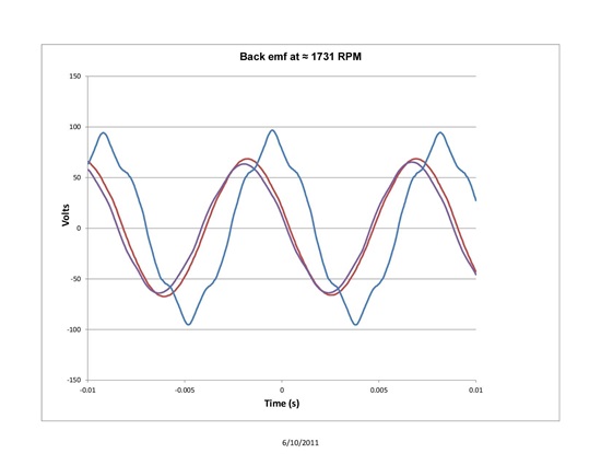
I have been using the older TI motor control software for several years now (since 2010). I have been running a two head air compressor that spins between 500 to 2000 rpm and pulls about 230 watts at max load and speed. The DC voltage to the motor drive is full wave rectified AC of about 150 volts DC under load. The motor is a custom 8 pole 12 teeth BLDC with an IPM rotor. The back emf wave shape is slightly trapezoidal (see non-sinusoid wave in image below), but seems to run fine with the sliding Mode Observer from the older TI code. The winding resistance as measured from line to line is 3 ohms (so 1.5 ohms per phase). The inductance as measured with LCR meter at 1 kHz from line to line is about 18 mH (so 9mH per phase). My old tunning values are as follows: 

Fsmo = 0.985
Gsmo = 0.73
Kslf = 0.157
Kslide = 0.5

Speed Kp = 0.6
Speed Ki = 0.005
Speed Kf = 0.0 

IqKp = 0.6
IqKi = 0.0318
IqKf = 0.0 

IdKp = 0.6
IdKi = 0.0318
IdKf = 0.0 

IqRef = 0.6  


I have been trying to use the new Insta_Spin FOC with the HV_PFC_Eval kit. When I run Lab 2b I get the following:

#elif (USER_MOTOR == My_Motor)

#define USER_MOTOR_TYPE                 MOTOR_Type_Pm

#define USER_MOTOR_NUM_POLE_PAIRS       (4) //8 pole motor ?

#define USER_MOTOR_Rr                   (NULL)

#define USER_MOTOR_Rs                   1.85

#define USER_MOTOR_Ls_d                 0.06921637)

#define USER_MOTOR_Ls_q                 0.06921637

#define USER_MOTOR_RATED_FLUX           0.4583907

#define USER_MOTOR_MAGNETIZING_CURRENT  (NULL)

#define USER_MOTOR_RES_EST_CURRENT      (3.0)

#define USER_MOTOR_IND_EST_CURRENT      (-3.0)

#define USER_MOTOR_MAX_CURRENT          (6.0)

#define USER_MOTOR_FLUX_EST_FREQ_Hz     (20.0)


When running the lab 2b the motor does seem to stall sometimes even when I increase the current.

Is the motor supposed to stall during this test?

Should I disconnect all load from the motor? Currently the motor is built into a two head compressor, but I do not load the compressor, however, some loading does occur from the friction of the compressor pistons.

When I try to run the motor RPM up to 2000 it stalls. From what I understand the current settings are in amps. If so, it seems these currents are high for what I am used to driving the motor. Typically at max load, I am not driving more than 2 amps, but with this software it seems 3 amps is just barely driving the motor.

My main question is… as long as the old sliding mode observer was able to work with this motor should the new FAST algorithm be able to work as well? Do you see anything about this motor that would concern you with your new software? I have only spent a day working on this, so I may figure a lot more out as I continue my efforts. Just thought i would check with you guys to make sure I am not missing something.

My main goal of switching to the new software is to hopefully gain more starting torque and to utilize the stator winding resistance feedback while the motor is running.


  • Gary H said:
    The winding resistance as measured from line to line is 3 ohms (so 1.5 ohms per phase). The inductance as measured with LCR meter at 1 kHz from line to line is about 18 mH (so 9mH per phase).

    The inductance you measured with InstaSPIN-FOC is significantly different. That's where I would focus first

    USER_MOTOR_Ls_d                 (0.06921637)

    Gary H said:

    When running the lab 2b the motor does seem to stall sometimes even when I increase the current.

    Is the motor supposed to stall during this test?

    During which test?  During Motor Identification

    1. Motor must be unloaded, or only slightly loaded.  The rotor has to spin constantly from RampUp until RampDown state.

    Gary H said:

    Should I disconnect all load from the motor? Currently the motor is built into a two head compressor, but I do not load the compressor, however, some loading does occur from the friction of the compressor pistons.

    It's better if you can. Typically if the compressor isn't loaded you can still ID...but again, if you have one of the motors outside the enclosure just use that for ID.

    Gary H said:
    When I try to run the motor RPM up to 2000 it stalls. From what I understand the current settings are in amps. If so, it seems these currents are high for what I am used to driving the motor. Typically at max load, I am not driving more than 2 amps, but with this software it seems 3 amps is just barely driving the motor

    Let's get proper parameters ID'd first, or if you like, simply load the Ls value you measured with your meter into the user.h (0.009).  BTW - if you know the salience of your motor you can enter it directly in user.h as well, note the Ls_d and Ls_q.

    Gary H said:
    My main question is… as long as the old sliding mode observer was able to work with this motor should the new FAST algorithm be able to work as well? Do you see anything about this motor that would concern you with your new software?

    Yes. No. You will get significantly better performance with InstaSPIN-FOC though.

    Gary H said:
    My main goal of switching to the new software is to hopefully gain more starting torque and to utilize the stator winding resistance feedback while the motor is running

    FAST will be able to take over at a lower operating point than the SMO, so that should help.  Yes, RsOnline will help quite a bit as well.

    Since you are familiar with SMO you may also want to look at the eSMO project in controlSUITE.  And since you have an IPM motor you could take advantage of the High Frequency Injection method to estimate an angle at 0 speed and give best start-up capability.  The difficulty in this solution is with the transition from HFI to eSMO angle.  InstaSPIN-FOC handles this automatically.

     C:\ti\controlSUITE\development_kits\HVMotorCtrl+PfcKit_v2.1\HVPM_Enhanced_Sensorless_2803x


  • Thanks for the quick feedback. I will try to remove all the load from the motor and try again. This may take a few days to get, but I will follow up with what I learn.

  • With a little help from a hammer and screwdriver, I was able to remove the pistons from the compressor so that the motor could freely spin. I reran the lab and got the following parmaters.

    #elif (USER_MOTOR == My_Motor)

    #define USER_MOTOR_TYPE                 MOTOR_Type_Pm

    #define USER_MOTOR_NUM_POLE_PAIRS       (4)

    #define USER_MOTOR_Rr                   (NULL)

    #define USER_MOTOR_Rs                   1.47)

    #define USER_MOTOR_Ls_d                 0.01135705

    #define USER_MOTOR_Ls_q                 0.01135705

    #define USER_MOTOR_RATED_FLUX           0.4322564

    #define USER_MOTOR_MAGNETIZING_CURRENT  (NULL)

    #define USER_MOTOR_RES_EST_CURRENT      (1.0)

    #define USER_MOTOR_IND_EST_CURRENT      (-1.0)

    #define USER_MOTOR_MAX_CURRENT          (4.0)

    #define USER_MOTOR_FLUX_EST_FREQ_Hz     (20.0) 

    Much better response!  Once I moved on to Lab 5b, I grabbed another fully assembled compressor and ran it through its passes. Everthing ran wonderfully. I was able to achieve much better performance especially at the lower RPMs. My next step is to move from the development kit to my system board. This will require a board layout change since I will be moving to the TMS320F28027F from a TMS320F28035, but the TMS320F28035 was a little too big for this system anyway. 

    Since this is a cost sensitive high volume product, I will also be looking for a lower cost solution for the current feedback. The OPA2350 is a little pricey. I will also investigate how my performance changes if I only use two current feedbacks instead of three in order to save the cost of another op-amp. I will also work with my local TI guy to find the best solution. I understand the Ifbs need to be high bandwidth op-amps, but does the Ifb-Sum op amp need to have a high bandwidth? Any suggestions for cost reductions would be appreciated. 

    Thanks for the help.

  • Gary H said:
    Much better response!  Once I moved on to Lab 5b, I grabbed another fully assembled compressor and ran it through its passes. Everthing ran wonderfully. I was able to achieve much better performance especially at the lower RPMs

    Thank you for posting!  Good to celebrate success on a forum that is mostly people working through challenges :)

    Gary H said:
    I will also investigate how my performance changes if I only use two current feedbacks instead of three in order to save the cost of another op-amp.

    The third current shunt is only required if you want to use over-modulation.  The default modution of (1.0) pure sinewave is supported with 2-shunt, and it may be possible to extend this to 1.15 modulation as well.  To move from 1.15 to 1.33 the third is required.

    Gary H said:
    I understand the Ifbs need to be high bandwidth op-amps, but does the Ifb-Sum op amp need to have a high bandwidth? Any suggestions for cost reductions would be appreciated. 

    With 3 shunts they do NOT need to be high bandwidth because you are always ignorning the shunt that is in a small sampling window where the bandwidth is required. Typically this is the same for 2 shunt limited to (1.0).  It gets into a grey area with 1.15 and 2 shunt.

    Here is our opinion on OP-AMP slew rate design:

    My suggestion is to have at least 5V/µs, and have an OPAMP that is pin to pin compatible with a 1V/µs or even 0.5V/µs. Then, go through all the required tests needed in the application, such as speed, transient conditions, input voltage variations, etc. Once the performance and all the tests have passed, only then, I would start lowering the slew rate step by step, so from 5 to 2, to 1, etc.

    This is because there are several factors that are taken into account when selecting an OPAMP, such as PWM frequency, maximum duty cycle used, layout, grounding, etc. That is why I am suggesting a higher slew rate to cover all tests before selecting a lower slew rate.


    We don't use the Ifb-sum in the InstaSPIN application examples, though it is common to sample this value or run it through a comparator for a Fault / Trip configuration.


  • Since my efforts above I have moved to trying to use the TMS320F28027F card on the TI high voltage board. I followed the same steps above with the same unloaded motor the only thing different was I was using the TMS320F28027F lab2b and not the 28069 card and lab. When I start the Flag_Run_Identify the motor hums and sometimes turns, but suddenly pulls a high current and opens my 10A circuit breaker on my AC supply. I tried the 69 card again and it works fine. Any suggestions on what to look at or try to determine the problem? I assume both cards should work the same.
  • do you have all the same relevant settings in the user.h for the F28027F project as the 69M project?
    Yes, expectation is that they work the same.

    does the over current happen within the first seconds(during OffsetCalc), few more seconds (RsRecalc), or as it tries to RampUp?
  • Gary,
    did you do the following form the HVKIT QSG?

    For controlCARDs without on-card isolated emulation, ex: TMDSCNCD28027F:
    a. Do NOT Populate M3-J5 (enables power to HVKIT emulator)
    b. Populate J9 (enables JTAG connection) when running projects from MCU RAM
    1. If you run a project from the MCU Flash you will need to remove this jumper to sever the JTAG connection and boot to flash properly

    I assume so, but checking...
  • Yes. I was able to load and run the lab2b from the CCS debug window. I even updated to the latest revisions of motorware and got the same result. I assmue all the jubers opn the 28027F card should stay in the default locations. I could try ordering another 28027F card just to make sure it not somthing wrong with the card. I assume the 28027F card uses the same harware connections as the 28069F card? So, if the 28069F card works that means nothing is wrong with the High Voltage board.
  • correct, I'm sure your HVKIT is fine.

    let me see if I can plug in a 27F and try a motor out...
  • I just tried it with HVBLDCMTR and didn't have any issues.

    I would check your user.h, especially your USER_MOTOR settings. Do you have a large USER_MOTOR_MAX_CURRENT set or something?
  • My user setting that I copied for the 28069 Lab are :

    #elif (USER_MOTOR == My_Motor)
    #define USER_MOTOR_TYPE MOTOR_Type_Pm
    #define USER_MOTOR_NUM_POLE_PAIRS (4)
    #define USER_MOTOR_Rr (NULL)
    #define USER_MOTOR_Rs 1.476//(0.3918252)
    #define USER_MOTOR_Ls_d 0.01135705//(0.00023495)
    #define USER_MOTOR_Ls_q 0.01135705//(0.00023495)
    #define USER_MOTOR_RATED_FLUX 0.4322564//(0.03955824)
    #define USER_MOTOR_MAGNETIZING_CURRENT (NULL)
    #define USER_MOTOR_RES_EST_CURRENT (0.6)
    #define USER_MOTOR_IND_EST_CURRENT (-0.6)
    #define USER_MOTOR_MAX_CURRENT (1.0)
    #define USER_MOTOR_FLUX_EST_FREQ_Hz (20.0)


    I will try a different motor and maybe order anoher 28027F card.
  • I really don't think it could be any issue with your controlCARD.

    Here are my settings

    CNCD28027F
    SW1: ON-ON
    SW2: OFF_ON
    SW3: ON-OFF
    SW4: OFF-ON

    HVKIT:
    J3/4/5/8/9: ON
    J7: middle jumped to pin toward CAPs (J7: 0-1-1)
  • this is low
    #define USER_MOTOR_MAX_CURRENT (1.0)

    not sure this is large enough to RampUp
  • I will give it all another look when I get back to it tomarrow. Yes, I set the current a little lower when the 10 amp breaker fliped. It was at 3 amps, but it do not seem to make a difference. I will make sure my system matches yours and I might even have your same motors around. Will let you know how it goes as soon as I get results.

    Thanks for the quick help.
  • Merry Christmas!!

    The trick was getting my jumpers on the CNCD28027F card correct just like you said.
    SW1: ON-ON
    SW2: OFF_ON
    SW3: ON-OFF
    SW4: OFF-ON

    I still had them in the default position.
    Everything is working as expected. I can now have a relaxing Christmas.
    Are these jumper positions in the “InstaSPIN Projects and Labs User’s Guide”?
    If not, they should be for lazy guys like me that never reads all the directions.

    I have my own board with the 28027F in layout currently and will be running a 200W compressor plus doing other system tasks. So, I am sure you will hear from me again before it’s all over.

    Thanks again, you are a life saver.
  • Hello,

    Gary H said:
    Are these jumper positions in the “InstaSPIN Projects and Labs User’s Guide”?
    If not, they should be for lazy guys like me that never reads all the directions.

    There is in motorware\motorware_1_01_00_13\docs\boards\control\f2802x\docs, but not in InstaSPIN Projects and Labs User's Guide.

     I was also the one that lazy to read all documents and got problem after that :)

    Cheers,

    Maria

  • Thanks Maria,

    I will give it a read. I know that this doc existed I just figured the board would work out of the box and it is sometimes hard to know where to look for certain docs especially when you have Conrtolsuite and Motorware. I only let a little smoke out of my motor:) Not enough to keep it from working. I learned my lesson "check all jumpers and switches and understand there function" before applying power!