This thread has been locked.

If you have a related question, please click the "Ask a related question" button in the top right corner. The newly created question will be automatically linked to this question.

Cannot reach max RPM

Other Parts Discussed in Thread: DRV8301-69M-KIT, DRV8301, BOOSTXL-DRV8301, LAUNCHXL-F28027F, MOTORWARE, CONTROLSUITE, DRV8312, DRV8303

Hello Chris and InstaSPIN community,

CCS Version: 5.4.0.00091 

I am using a custom low inductance, 3 paired pole, 9.8V, BLDC motor with DRV8301-69M-KIT.  After reading every piece of literature and forum post I could find I am still unable to spin the motor at the rated 20krpm.  At this point in time I am able to hit right around 14krpm.  I have varied the USER_PWM_FREQ_kHz from 10 to 80 as well as tried increasing #define USER_MAX_VS_MAG_PU to 1.333, as in lab10.

I read that I may get poor results at a bus voltage of 9.8 due to ADC resolution.  Is there a method recommended for altering the board to solve this issue?

My goal is: Speed control from 300 rpm - 20krpm

The best results I could get so far are with the attached user.h file

Thanks in advance!

USER_PWM_FREQ_kHz = 25
USER_MAX_VS_MAG_PU = 1.0

7282.user.h

  • Jonathan,

    First, I appreciate you reading and trying everything yoursefl. 

    Let's take a look at some things.

    20 KRPM w/ 6 poles = 1 KHz.  Very reasonable. 

    1.

    in your user.h there is a major issue if you are using the sensorless projects

    #ifndef QEP
    #define USER_IQ_FULL_SCALE_FREQ_Hz        (1100.0)   // 800 Example with buffer for 8-pole 6 KRPM motor to be run to 10 KRPM with field weakening; Hz =(RPM * Poles) / 120
    #else
    #define USER_IQ_FULL_SCALE_FREQ_Hz        (USER_MOTOR_NUM_POLE_PAIRS/0.008)   // (4/0.008) = 500 Example with buffer for 8-pole 6 KRPM motor to be run to 6 KRPM; Hz = (RPM * Poles) / 120
    #endif

    you need to have
    #define USER_IQ_FULL_SCALE_FREQ_Hz        (1100.0)

    regardless just to hit your rated speed.

    The maximum you should ever set this variable is

    #define USER_IQ_FULL_SCALE_FREQ_Hz        (4 * USER_VOLTAGE_FILTER_POLE_Hz)

    2.

    While you did the right thing here

    #define USER_IQ_FULL_SCALE_VOLTAGE_V      (9.8)

    this is just way too low for the hardware scaling of this EVM.

    #define USER_ADC_FULL_SCALE_VOLTAGE_V       (66.32)

    In fact, I usually don't run the DRV8301 EVM under 15V...below that while it "should" work, I have seen issues with the voltage dropping out to the digital side. Also, in your case with this low flux motor, the resolution of 9.8V to 66.32V is just too poor. I'm actually quite surprised that you were able to ID this motor.

    If you change the resolution / scaling on this EVM to something like 15V ADC_V I think you will have success.  I *know* you will have success if you use the BOOSTXL-DRV8301 + LAUNCHXL-F28027F, which has better resolution.

    Your Rs / Ls is quite strange....it is only 316 Hz.  You should have an R / L > 1 Khz. . If you assume your Rs is correct at 3.8mH that would imply that your Ls needs to be <3.8uH.  This is going to have a crazy current ripple....the DRV8301 EVM has no hope of controlling this at low or high speeds.  You must improve tjhe current feedback and resolution.

    This motor has minute flux, minute Rs, and minute Ls....it's a very bad candidate for high performance FOC control.  I think you *might* be able to get something to work reasonably, but it's not ideal.  Especially since this is a custom motor I would have to question WHY it was designed with such motor parameters?  They just don't make much sense.

    Back to your user.h:

    - I would PWM as fast as possible with this motor. For motor ID I like to limit to 45 KHz  PWM / 15 KHz current/est, but once ID'd and running with the 69M you can try 60 KHz / 20 KHz.  In the user.h you are using you have 25 KHz PWM and then 25/3 = 8.3 KHz current/est and <600Hz speed.

    If you use better HW scaling it should improve things...but if this is really a 3uH motor with 200A of short circuit current it's going to be tough to control with current control / current sampling techniques.  I would highly recommend designing this motor in a different way.  Keeping the Ls to > 30uH will make a world of difference.

    So Rs > 0.03 ohm, Ls > 30uH, and an appropriate flux for the torque you require...something > 0.015 V/Hz to give Isc = 2* Irated (which you show as 40A).  This will be a well designed motor.


  • Hello Chris,

    Thank you for your quick reply!

    1)  I took care of this issue by wiping out the if/else statement and just defining IQ_Freq to 1100

    2)  Is there a way to decrease the USER_ADC_FULL_SCALE_VOLTAGE_V?  I would like to continue using this dev board because it has the MCU that I plan on going into production with.

    3)  The Rs/Ls measurements seems to be dependent on the USER_MOTOR_RES_EST_CURRENT and USER_MOTOR_IND_EST_CURRENT values.  I know that it is recommended 10% full scale but that seems vague when it is determining values that are so critical.  Per the spec sheet the motor Rs/Ls is 0.027/0.0000055 = 4900 Hz..  But this is not what the system is measuring (Maybe the ADC resolution issue).

    4)  I am going to change the voltage supply to 15V and make the adjustments you recommended to evaluate performance increase this evening.

    5)  I reviewed the other eval board you recommended and the main difference I see is that is has a 60MHz clock vs 90MHz in the 69M.  I would prefer to get the benefits with the MCU of our eval kit and figure out a way to achieve better ADC resolution.

    6)  Would it be possible for you to put me in contact with a local FAE?  We are looking into taking this design into production by the end of the year and need a rep to discuss our schematic with.  

    7)  Your expertise and assistance is greatly appreciated and I cannot thank you enough!

    Best,
    Jonathan 

  • couple quick comments before I need to run

    Jonathan Azevedo said:

    2)  Is there a way to decrease the USER_ADC_FULL_SCALE_VOLTAGE_V?  I would like to continue using this dev board because it has the MCU that I plan on going into production with.

    See SPRUHJ1 chapter 5.  You can change the scaling range just by dropping an approprite resistor onto the voltage sense circuits.  This will give you the biggest improvement. 

    3)  if the R/L of the motor is > 2000 you MUST use proj_lab02c to ID the motor. period. 

    as RoverL state is finished please look at the controller_obj variable RoverL and post the value.

    with the DRV8301 EVM we still see some current sampling issues with motors like this...the BOOSTXL-DRV8301 gives significantly better results.

    5) The main benefit is on the BOOSTXL-DRV8301 board. It's just superior and scaling and current sensing layout....good data in = good control.

    6) possibly, but the local FAE won't have more knowledge than we do here to be honest with you.  If you use a distributor like Arrow or Avnet that will be your best bet for schematic review.

    7) you're welcome


  • Hi Chris,

    Great news, it seems to have been a resolution problem, as you thought!  I am now able to operate the system 21krpm+.

    Are there any tricks to smooth out the start up to get rid of the little jerk and increase torque at low speed?

    The identification of the motor is now R/L = 0.013927/4.6688E-6

    I wouldn't imagine to find anyone more knowledgeable than you on this topic after reading hundreds of your postings.  Mainly just want some local TI support down here in which we are not getting...

    With that being said, would you mind taking a look at the attached schematic to make sure there are no obvious mistakes or if we could do something to improve current sense for the system?

    4087.ADEX_BLDC_Rev0_Schematic.pdf

    Have a great weekend!

    Best,
    Jonathan

  • Hi Chris,

    We updated the current sensing portion of the schematic to add an opamp on the third phase.

    I looks like the both the DRV8301 and DRV 8303 are only sensing two phases.  The 69M kit does not add any discrete hardware to add sense to the third phase.  However, it appears that they do add this third phase sensing on the boostxl board.

    Is this why you mention that the board is superior?

    5342.ADEX_BLDC_Rev0_B_Schematic.PDF 

    Thanks,
    Jonathan

  • The DRV8301 IC only has 2 on-chip amplifiers.

    On the DRV8301 EVM, for the MotorWare projects we actually use the currents that bypass the DRV8301 amplifiers entirely and only use the off-chip OPA.

    On the DRV8301 BOOSTXL-DRV8301 we use the two on-chip amplifiers for phase A and B and use a single off-chip OPA for phase C.

    Jonathan Azevedo said:
    Is this why you mention that the board is superior?

    No. The layout of the EVM current sampling is non-ideal.  The amplification is done near the shunt and then long traces are run to the ADC input pin.  This is causing issues with the phases picking up noise, even from each other.  It really limits the PWM frequency you can run (higher is worse on this board) and the maximum modulation (gets much worse as your sampling windows get smaller at high speed).

    The BOOSTXL has a superior current sense layout with the amplification done as close as possible to the MCU (which is on the mother board).  When you make your own single PCB it is best to get the signals even close to the MCU ADC pins before the opamps if possible.  This is harder to do with 2 of those amplifier are in the DRV8301 IC which is going to be closer to the FETs.....

  • Chris,

    Thank you for the explanation of the differences between the two boards.  I have been able to find the schematic and layout of the BoostXL-DRV8301 but cannot locate for the DRV8301-69M-KIT.  Could you please help me track down the schematic as I need to decrease the ADC voltage feedback from 66.3V to 10V and also trace GPIO to headers.

    I have been probing around the board and have been able to find the 95.3k resistors for phase's A and B, but no luck for C.  Maybe this board does not sense across all three phases?  This is where the schematic would be extremely helpful.

    Thanks,
    Jonathan 

  • I have still not been able to find the schematic, but did find some of the questions to my answers embedded within the motorware documentation.

    Just wanted to keep others informed if they are looking for the same information ;)

  • the schematics for the DRV8301 are kept in controlSUITE to keep MotorWare as small as possible (and not duplicate content)

    C:\ti\controlSUITE\development_kits\DRV830x-HC-C2-KIT_v105\~DRV830x-HC-EVM-HWdevPkg\DRV830x_RevD_HWDevPKG

    if you run MotorWare.exe it explains this and points to this location


  • Chris,

    I was able to locate the 3 R_vu's and replace them with 15k resistors, as to provide a ADC FULL SCALE of 13.22V. The C_v caps were not changes, so the voltage filter is now different.

    The following scaling was adjusted for in user.h:

    #define USER_IQ_FULL_SCALE_VOLTAGE_V (9.8)
    #define USER_ADC_FULL_SCALE_VOLTAGE_V (13.22)

     Issues:

    The calculated bus voltage is now reporting just over 1V.  The controlCard is also getting extremely hot.  Not sure if this is a related problem or not, but it is concerning.  The MCU is too hot to even touch.

    The one thing a am pretty sure of is that the hardware change was successful.  I suspect this because if I change the ADC full scale voltage back to the default the voltage bus shows the correct value of 9.8V.  We are also able to run the motor.  The interesting fact is that we are now capped at a speed of 16.5k, where we were well north of 20k prior to the resistor change and running at 24V.

    Thanks,
    Jonathan

  • it looks like you didn't make the same change to the reading of the Vbus voltage. It also needs to have the same scaling.

    and then recalculate the filter pole and update that in user.h

    you want to keep this filter pole reasonable small, under <500 Hz is preferred and ideally just greater than your max frequency / 4, but certainly keep it under 700 Hz.


  • Hi Chris,

    Thanks for all of your support in the past. We have our custom motor controller board completed and are in the process of identifying and tuning the motor control. I'm following up on this thread because it is the same motor and schematic which you reviewed in the past.

    We're having difficulty spinning at high rpm (>10krpm) and have a few follow up questions for you. There is a little more noise than I expected in the measured current signals. Do you have any example scope shots of the measured motor phase voltages and currents that I can use as a reference?

    We're able to use the lab_02c to identify the motor parameters, but once identification is complete and we re-enable the motor and command a particular speed, it is unstable. How are the gains changed from the identification phase to the on-line phase?

    We would very much like to tune the FAST current loop in real-time on a scope, as described in lab_05a. Where is the reference trajectory set in the project code? I'd like to be able to drive the reference current and tune for different step and sine waveforms. Will I be able to measure the reference signal as an output on my scope? Also which current signal should I measure for tuning purposes? i.e. phases A, B, or C?

    Does the DRV-8301-69M dev kit use an internal or external oscillator? And do you see a performance difference at high speeds?

    Thanks again for your support!

    Best regards,

    Chris

  • Also, one other question, what is the difference between the Iq and Id signals, and also the Kp_iq and Kp_id gains.

    Thanks,

    Chris

  • Hi Chris,

    Another question that just came up is what's the difference between the CTRL_setKi and PID_setKi functions? I see that in some examples both of these constants are set, but in other examples, only the CTRL_setKi gains are set.

    I'm trying to modify lab_04 to simply drive a reference current signal, and adjust the Kp and Ki gains to tune my controller. But it seems that the gains are being updated elsewhere in the software, perhaps during some automatic identification. What do you propose to disable all of this other functionality and create a simple program to tune the current gains?

    Thanks,

    Chris

  • Chris Lightcap said:
    There is a little more noise than I expected in the measured current signals.

    Remind me about your motor, attach the user.h.

    Your HW is based on BOOSTXL-DRV8301?

    Chris Lightcap said:
    Do you have any example scope shots of the measured motor phase voltages and currents that I can use as a reference?

    There are scope shots in SPRUHJ1, but not of high speed. I posted some high speed (4 KHz) scope shots using DRV8312 recently:

    http://e2e.ti.com/support/microcontrollers/c2000/f/902/p/339361/1242590.aspx#1242590

    Chris Lightcap said:

    We're able to use the lab_02c to identify the motor parameters, but once identification is complete and we re-enable the motor and command a particular speed, it is unstable. How are the gains changed from the identification phase to the on-line phase?

    1. proj_lab02# is only for motor ID, it shouldn't even run the motor after ID.

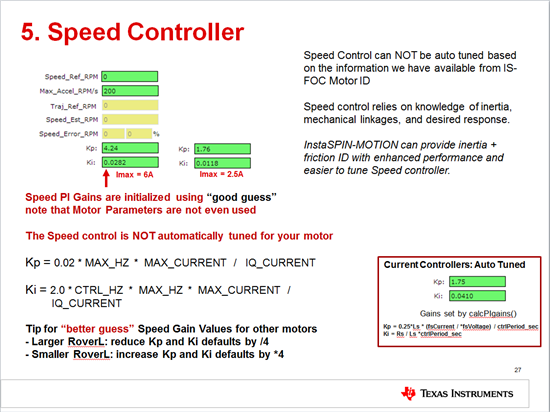
    2. Once you start up a motor using the user.h values the speed controller gains are set to the default. Recall that these are NOT tuned.  You have to auto tune them.  During ID the speed controller is not tuned either, most of it is running under an open loop strategy and we slowly close the torque loops.

    This is from a workshop I'm running.


    Chris Lightcap said:
    Where is the reference trajectory set in the project code?

    The trajectory output is calculated from the starting speed, ending speed, acceleration, and trajectory frequency of operation.

    from ctrl.c

    void CTRL_setup(CTRL_Handle handle)
    {
      CTRL_Obj *obj = (CTRL_Obj *)handle;

      uint_least16_t count_traj = CTRL_getCount_traj(handle);
      uint_least16_t numCtrlTicksPerTrajTick = CTRL_getNumCtrlTicksPerTrajTick(handle);


      // as needed, update the trajectory
      if(count_traj >= numCtrlTicksPerTrajTick)
        {
          _iq intValue_Id = TRAJ_getIntValue(obj->trajHandle_Id);

          // reset the trajectory count
          CTRL_resetCounter_traj(handle);

          // run the trajectories
          CTRL_runTraj(handle);
        } // end of if(gFlag_traj) block

      return;
    } // end of CTRL_setup() function


    Chris Lightcap said:
    I'd like to be able to drive the reference current and tune for different step and sine waveforms. Will I be able to measure the reference signal as an output on my scope?

    You'll have to add your own Traj module to do this. Currently in proj_lab05a you are directly commanding the IqRef_A to the input of the Iq PI controller.  So you are setting a step input only.  If you create your own front end Traj you can shape this input. It's very useful in a practical applciation of a torque control system anyways, like an e-Bike.

    Chris Lightcap said:
    Will I be able to measure the reference signal as an output on my scope? Also which current signal should I measure for tuning purposes? i.e. phases A, B, or C?

    you could take any of your data and put it out on PWM DAC pins.  If you have a current probe that is always preferred. Very useful if you are doing power electronics, I highly recommend purchasing one.  This allows you to just loop around any phase wire and get a view of the current in real-time.

    Chris Lightcap said:

    Does the DRV-8301-69M dev kit use an internal or external oscillator? And do you see a performance difference at high speeds?

    We are using the internal oscillator on the controlCARD. The OSC can drift with temp, so you need to run the OSC calibration/compensation for full robustness.  If the clock drifts you will see a drift in the speed estimates.  But that's pretty minor and not related to how fast your motor is going.. I would say what you are seeing is related to quality of the current sample.

    Also, one other question, what is the difference between the Iq and Id signals, and also the Kp_iq and Kp_id gains.

    Iq is the torque component and Id is the field component of the D-Q co-ordinate system (the DC co-ordinate system that we transform into from 3-ph to 2-ph (CLARKE)  and 2-ph to DC (PARK).

    In a standard current control system the Kp and Ki values for these two PI controllers can generally be set the same for good performance.

    what's the difference between the CTRL_setKi and PID_setKi functions?

    the PID structures are members of the CTRL, so using CTRL_setXXX passes the values into the CTRL system where they are set. Using PID_setXXX can pass them directly.

    I noticed we are only doing this in proj_lab02x in the recalcpKpKi function, and we actually pass the value through CTRL and then also PID.....hmmmmm.  I'm not really sure why we are doing that, let me check.

    You'll notice in updateKpKiGains() function we just pass through the CTRL system, which is my recommendation.

    I'm trying to modify lab_04 to simply drive a reference current signal, and adjust the Kp and Ki gains to tune my controller. But it seems that the gains are being updated elsewhere in the software, perhaps during some automatic identification. What do you propose to disable all of this other functionality and create a simple program to tune the current gains?

    proj_lab04 does not interface to the CTRL_setKxxxx or PID_setKxxx functions.  Use proj_lab05a for Torque control with the functions that interface with the Iq and Id PI controllers.


  • Hi Chris,

    Thanks for the feedback.

    Hardware is based on the BOOSTXL-DRV8301.

    I've attached our user.h file for you to review.

    Our scope shots definitely look nothing like your clean sine signal. You can see the PWM switching in our signal. Should we add a cap on the output to smooth the current sense signals? Also I noticed in the other forum that you recommended adding an external inductor. Would you recommend the same for our case considering that we're using a 5.5uH inductance motor? It would be difficult to add this in-circuit at this point, but would it be possible to add them in series with the motor phases?

    I'll try project lab05a to set the current/torque reference signals.

    Best,

    Chris

    user.h
  • user.h

    It looks like you set this based on your IQ_FREQUENCY of 1100 / 4

    #define USER_VOLTAGE_FILTER_POLE_Hz  (275.00)

    this pole needs to actually match the HW pole of the voltage filter as described in SPRUHJ1 Ch 5


    your decimation wasn't correct. For 90 MHz F2806x and 60 MHz PWM try this

    //! \brief DECIMATION
    // **************************************************************************
    //! \brief Defines the number of pwm clock ticks per isr clock tick
    //!        Note: Valid values are 1, 2 or 3 only
    #define USER_NUM_PWM_TICKS_PER_ISR_TICK        (3)

    //! \brief Defines the number of isr ticks (hardware) per controller clock tick (software)
    //! \brief Controller clock tick (CTRL) is the main clock used for all timing in the software
    //! \brief Typically the PWM Frequency triggers (can be decimated by the ePWM hardware for less overhead) an ADC SOC
    //! \brief ADC SOC triggers an ADC Conversion Done
    //! \brief ADC Conversion Done triggers ISR
    //! \brief This relates the hardware ISR rate to the software controller rate
    //! \brief Typcially want to consider some form of decimation (ePWM hardware, CURRENT or EST) over 16KHz ISR to insure interrupt completes and leaves time for background tasks
    #define USER_NUM_ISR_TICKS_PER_CTRL_TICK       (1)      // 2 Example, controller clock rate (CTRL) runs at PWM / 2; ex 30 KHz PWM, 15 KHz control

    //! \brief Defines the number of controller clock ticks per current controller clock tick
    //! \brief Relationship of controller clock rate to current controller (FOC) rate
    #define USER_NUM_CTRL_TICKS_PER_CURRENT_TICK   (1)      // 1 Typical, Forward FOC current controller (Iq/Id/IPARK/SVPWM) runs at same rate as CTRL.

    //! \brief Defines the number of controller clock ticks per estimator clock tick
    //! \brief Relationship of controller clock rate to estimator (FAST) rate
    //! \brief Depends on needed dynamic performance, FAST provides very good results as low as 1 KHz while more dynamic or high speed applications may require up to 15 KHz
    #define USER_NUM_CTRL_TICKS_PER_EST_TICK       (1)      // 1 Typical, FAST estimator runs at same rate as CTRL;

    //! \brief Defines the number of controller clock ticks per speed controller clock tick
    //! \brief Relationship of controller clock rate to speed loop rate
    #define USER_NUM_CTRL_TICKS_PER_SPEED_TICK  (20)   // 15 Typical to match PWM, ex: 15KHz PWM, controller, and current loop, 1KHz speed loop

    //! \brief Defines the number of controller clock ticks per trajectory clock tick
    //! \brief Relationship of controller clock rate to trajectory loop rate
    //! \brief Typically the same as the speed rate
    #define USER_NUM_CTRL_TICKS_PER_TRAJ_TICK   (20)   // 15 Typical to match PWM, ex: 10KHz controller & current loop, 1KHz speed loop, 1 KHz Trajectory


    This is too high, especially since your motor at 1100 Hz will only produce 6.6V of Bemf

    set this to your bus voltage...looks liik you are using 12.x for ADC, so use (12.0) here

    #define USER_IQ_FULL_SCALE_VOLTAGE_V      (26.5)


  • Ok, we made the changes and can correctly identify the motor. But we're not able to use project 5a as you suggested to drive a constant current signal. The current is quite noisy in our setup, did you get a chance to see my other question in the last post?

    "Our scope shots definitely look nothing like your clean sine signal. You can see the PWM switching in our signal. Should we add a cap on the output to smooth the current sense signals? Also I noticed in the other forum that you recommended adding an external inductor. Would you recommend the same for our case considering that we're using a 5.5uH inductance motor? It would be difficult to add this in-circuit at this point, but would it be possible to add them in series with the motor phases?"

    Thanks,

    Chris

  • what did you change this to?

    #define USER_VOLTAGE_FILTER_POLE_Hz  (275.00)

    at what RPMs to you start to see issues?  You think this motor will go 22 KRPM, correct?

    Also I noticed in the other forum that you recommended adding an external inductor. Would you recommend the same for our case considering that we're using a 5.5uH inductance motor?"

    Your user.h says you have a 20A motor, but you have a short circuit current of 159A. That's "over designed" by about 4x.

    So you could increase your Ls by 4x and still get the same torque capability with InstaSPIN-FOC.  However, going from 6uH to 24uH won't buy you that much...it would be better if you could get to 50uH+, but then you will reduce some torque performance.

    With motors that have THIS little flux and THIS little inductance I would say that a flux based observer and lower shunt sampled current control approach probably isn't the most worthwhile.

    It would be difficult to add this in-circuit at this point, but would it be possible to add them in series with the motor phases?

    No, that causes probablems with the estimation since the Vph samples are no longer real.

  • I changed the actual filter pole to

    #define USER_VOLTAGE_FILTER_POLE_Hz  (286.830)

    We've actually driven this motor to 22krpm with the DRV8301-69M-KIT and a little tuning, so I'm confident that we can achieve this again with our current design.

    I'm wondering if we may see a performance improvement running at a much higher PWM frequency, perhaps as high as 80kHz, since this is an extremely low inductance motor. I wasn't able to find the software lab example using a software que to enable faster ISR frequencies. Where can I find an example of this technique?

    Thanks again for all of your support!

    Chris

  • Hi Chris,

    We're able to get the motor running at roughly 17 kRPM, and are working on improving the low speed performance while loaded. I read through chapter 15 in the instaSPIN motion user's guide, and have tried adjusting my force angle frequency as you suggested in another post:

    #define USER_ZEROSPEEDLIMIT (0.01 / USER_IQ_FULL_SCALE_FREQ_Hz)

    #define USER_FORCE_ANGLE_FREQ_Hz (2.0*USER_ZEROSPEEDLIMIT*USER_IQ_FULL_SCALE_FREQ_Hz)

    The user zero speed limit seems low but it actually works better at lower frequencies (otherwise the motor may jerk several times before starting to spin). I'd like to be able to tune my current and bandwidth gains while looking at a real-time plot. I've tried loading the graph file described in lab_05f, but the graph doesn't scroll when updated so I'm never looking at the most recently acquired data.

    1. How do you adjust the graph settings so that it automatically scrolls with new data (I've already set it to auto refresh)?

    2. I can view the commanded or reference current IqRef_A, but how can I output my actual current, both in the list of expressions and in a graph? I tried adding Iq_A but this isn't being updated in the code.

    3. Do you have any other suggestions for good torque performance at low speeds using the spinTAC controller? How does the FOC controller compare at low speeds?

    4. Do you have any examples of achieving RPM higher than allowed from back-EMF using field weakening?

    Thank you again for all of your help.

    Best regards,

    Chris

  • One more thing to add, I was able to output both IqRef_A and Iq_A as expression in project lab_05f, but at least looking at the expressions list, my current tracking performance looks very poor. I'm assuming that these two numbers should be right on top of each other. I'm very interested in seeing a graphical display in real-time of these values.

    Best regards,

    Chris

  • Chris Lightcap said:
    I'm wondering if we may see a performance improvement running at a much higher PWM frequency, perhaps as high as 80kHz, since this is an extremely low inductance motor.

    I don't think it will help much. The main cause is in getting a valid average current sense sample.

    IF you had good values then running PWM at faster frequency CAN help, but I doubt over 60 KHz will make that much of a difference on your HW.

    Chris Lightcap said:

    I wasn't able to find the software lab example using a software que to enable faster ISR frequencies. Where can I find an example of this technique?

    we haven't published this...sometime in 2015 we will publish a que example.

    Right now you can only use the user.h decimation settings and keep the effective current/estimator to 15 KHz max for F2802x and maybe 30 KHz for F2806x.

  • Chris Lightcap said:
    The user zero speed limit seems low but it actually works better at lower frequencies (otherwise the motor may jerk several times before starting to spin).

    The jerk you see is normal - or at least can happen depending on application - as it's part of the ForceAngle method. The point of force angle logic is to keep a moving angle in the feedback loop to keep trying to get the rotor moving so that FAST can take over and then provide a proper "real" angle. 

    Many applications will work better (less jerky) if you disable ForceAngle entirely.

    Chris Lightcap said:
    I'd like to be able to tune my current and bandwidth gains while looking at a real-time plot. I've tried loading the graph file described in lab_05f, but the graph doesn't scroll when updated so I'm never looking at the most recently acquired data.

    do you have the refresh enabled?

    Chris Lightcap said:
    I tried adding Iq_A but this isn't being updated in the code.

    we start pulling this in labs 9 and 10. You can add it to your own project:

    // read Id and Iq vectors in amps
    gMotorVars.Id_A = _IQmpy(CTRL_getId_in_pu(ctrlHandle), _IQ(USER_IQ_FULL_SCALE_CURRENT_A));
    gMotorVars.Iq_A = _IQmpy(CTRL_getIq_in_pu(ctrlHandle), _IQ(USER_IQ_FULL_SCALE_CURRENT_A));

    // calculate vector Is in amps
    gMotorVars.Is_A = _IQsqrt(_IQmpy(gMotorVars.Id_A, gMotorVars.Id_A) + _IQmpy(gMotorVars.Iq_A, gMotorVars.Iq_A));

    Chris Lightcap said:
    3. Do you have any other suggestions for good torque performance at low speeds using the spinTAC controller? How does the FOC controller compare at low speeds?

    with your really low flux motor you aren't going to get good low speed performance. It takes larger flux (EMF voltage produced @ a Hz) relative to the voltage scale of your hardware.

    ex: 0.5 V/Hz @ 2 Hz = 1.0 V Bemf, on a 12V HW this is 8.3 % and will work well.

    ex: 0.01 V/Hz @ 2 Hz = 0.02V Bemf, on a 66V HW this is 0.03% and will NOT work well

    But yes, a component of good speed control - once you have good rotor feedback - is the tuning of the speed loop. And SpinTAC is superior in this respect vs. PI controls.  It gives better performance, easier to tune, and the tuning works across the entire operating range (no gain staging).

    Chris Lightcap said:
    4. Do you have any examples of achieving RPM higher than allowed from back-EMF using field weakening?

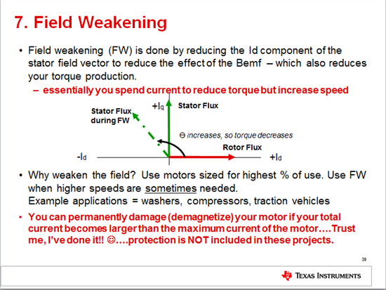
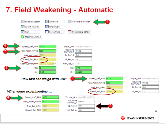
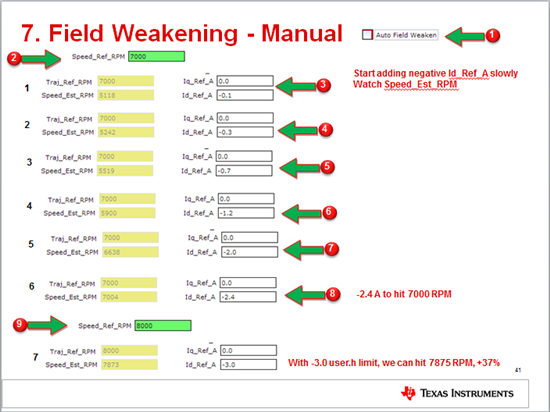
    proj_lab09 is Field Weakening. You can use the "automatic" example, or just provide your own negative IdRef.  Sorry, we haven't finished the lab write-up, but the lab itself works.

  • Chris Lightcap said:
    One more thing to add, I was able to output both IqRef_A and Iq_A as expression in project lab_05f, but at least looking at the expressions list, my current tracking performance looks very poor. I'm assuming that these two numbers should be right on top of each other. I'm very interested in seeing a graphical display in real-time of these values.

    are you pulling values inside an interrupt? in our labs we are pulling the values in the background task, so there isn't anything that guarantees they are synchronized. 

    your expression list also isn't "keeping up" with real-time data, at least not at the control frequency rate.

    to really check this you would need to actually "get" inside the interrupt and datalog all the data and then compare it off-line.

  • ChrisClearman said:

    what's the difference between the CTRL_setKi and PID_setKi functions?

    the PID structures are members of the CTRL, so using CTRL_setXXX passes the values into the CTRL system where they are set. Using PID_setXXX can pass them directly.

    I noticed we are only doing this in proj_lab02x in the recalcpKpKi function, and we actually pass the value through CTRL and then also PID.....hmmmmm.  I'm not really sure why we are doing that, let me check.

    You'll notice in updateKpKiGains() function we just pass through the CTRL system, which is my recommendation.

    [/quote]

    I looked into this, and using the PID_set isn't necessary if using the CTRL_set. This should be removed from proj_lab02 labs in next version of MotorWare.

  • Hi Chris,

    Thanks again for all of your feedback. I was able to get the graph to scroll correctly by setting the acquisition buffer size to 1. I've been able to improve my startup performance a little by adjusting the user speed and force angle parameters, but I'm still not able to realize my full motor torque. It seems that under load, the estimated motor speed drops below zero and becomes quite large (roughly ~2-4kRPM in the negative direction). This causes my target and estimated motor currents to max at 20Amps. I can see 20Amps on the graphical display, but I feel no reaction torque from the motor. It almost seems that the driver has been disabled, or that the estimated current is considerably incorrect.

    I'm using the DRV8301 and confirmed that the over current limit is set to the max, and that no faults are generated when applying a load to the motor. Do you have any suggestions why I may be seeing this result while loaded?

    I'm only trying to drive in a single direction, so is there a way to improve performance by limiting motor direction estimates?

    Best regards,

    Chris

  • Chris Lightcap said:
    It seems that under load, the estimated motor speed drops below zero and becomes quite large (roughly ~2-4kRPM in the negative direction).

    Are you already running at a reasonable speed when you apply load?  If your parameters are correct (and not changing) and you are above a minimum speed, you should have electrical flux alignment and be able to generate nearly full torque, assuming your controllers are properly tuned.

    If you are trying to load the motor at start the estimator is not producing a reliable angle yet so you won't have electrical alignment and be able to generate full torque.


  • I believe that I'm running at a reasonable speed, roughly 1-2kRPM. Would you see a loss of motor efficiency if my estimated motor inductance was not correct?

    On a scope, I'm actually seeing large current spikes at the PWM gate transitions, which do not appear to be due to deadband problems. This causes my controller to run at a much higher current and lower efficiency. Would this be caused by an incorrect motor inductance?

    There is one idea that may significantly improve performance. There are a pair of analog hall sensors measuring the rotor position, so I could use these signals to estimate a motor velocity. Would it be possible to bypass the FAST velocity estimate and use these measured values instead? It's also possible to estimate traditional digital hall sensor positions from these sensor measurements. Would I be able to use this information to estimate electric angle and improve performance?

    Thanks,

    Chris

  • Chris Lightcap said:
    Would you see a loss of motor efficiency if my estimated motor inductance was not correct?

    inductance parameter has more influence on angle estimation at high speed. Yes, if not correct it can have an effect. But not for low speed.

    This could be an issue of getting good current samples.
    It can also be an issue of your speed controller not responding quickly enough.
    You can also try multiplying your Kp of Iq/Id by 4 for stiffer current response.

    Chris Lightcap said:

    On a scope, I'm actually seeing large current spikes at the PWM gate transitions, which do not appear to be due to deadband problems. This causes my controller to run at a much higher current and lower efficiency. Would this be caused by an incorrect motor inductance?

    This is due to low inductance machine which causes large short circuit / switching current.  You're going to see this with these kind of motor designs. One reason they are so poor.

    Chris Lightcap said:
    Would it be possible to bypass the FAST velocity estimate and use these measured values instead?

    It is possible. At low speed it may give better angle information, but it will only be accurate to 15-30 degrees, so not perfect.  At high speed it will actually be worse as you will have such a delay in the calculation, it's one of the main issues with hall sensors for high speed motors. FAST will work better than mechanical sensos at high speed (assuming everything else is ok).


    Again, the main issue here is the approach of doing closed loop, high frequency field oriented current control using a motor with terrible current ripple / switching current and a current sensing scheme that makes it very challenging to get the needed inputs.


  • Hi Chris,

    One question that came up this morning is how do I configure my faults in hal.c for a custom board. It appears that you're using trip zones 2, 3, and 6 on the dev board, but these are not configured for my MCU. My OCTW and FAULT pins are connected to GPIO inputs as follows:

    // OCTWn

    GPIO_setMode(obj->gpioHandle,GPIO_Number_7,GPIO_7_Mode_GeneralPurpose); // GPIO_13_Mode_TZ2_NOT **

    // FAULTn
    GPIO_setMode(obj->gpioHandle,GPIO_Number_8,GPIO_8_Mode_GeneralPurpose); // GPIO_14_Mode_TZ3_NOT **

    Here's a sample of code from hal.c that sets the faults:

    for(cnt=0;cnt<3;cnt++)

    {
    PWM_enableTripZoneSrc(obj->pwmHandle[cnt],PWM_TripZoneSrc_CycleByCycle_TZ6_NOT);

    PWM_enableTripZoneSrc(obj->pwmHandle[cnt],PWM_TripZoneSrc_CycleByCycle_TZ3_NOT);

    PWM_enableTripZoneSrc(obj->pwmHandle[cnt],PWM_TripZoneSrc_CycleByCycle_TZ2_NOT);

    // What do we want the OST/CBC events to do?
    // TZA events can force EPWMxA
    // TZB events can force EPWMxB

    PWM_setTripZoneState_TZA(obj->pwmHandle[cnt],PWM_TripZoneState_EPWM_Low);
    PWM_setTripZoneState_TZB(obj->pwmHandle[cnt],PWM_TripZoneState_EPWM_Low);
    }

  • just update which fault (or both) you want to be CycleByCycle and which you want to be OneShot (if any)

    in the hal.c for the hvkit you can look for this function and see what we do there

    HAL_hvProtection

  • Thank you again.

    I don't see where TZ6_NOT is tied to any pins in the drv8301 dev kit example. Is this defined elsewhere in the program? Is there a default input?

    PWM_enableTripZoneSrc(obj->pwmHandle[cnt],PWM_TripZoneSrc_CycleByCycle_TZ6_NOT);

  • from SPRUH18

    section 3.2.7

    TZ1 to TZ3 are sourced from the GPIO mux. TZ4 is sourced from an inverted EQEP1ERR signal on those devices with an EQEP1 module. TZ5 is connected to the system clock fail logic, and TZ6 is sourced from the EMUSTOP output from the CPU.

  • Excellent, thanks again for the quick response. One last question for the moment, what is the best voltage filter pole for a 1000Hz motor (20000 * 3 pole pairs / 60). I found in one document that it should be roughly equal to you max motor frequency, and then in another that it should be roughly 1/4 of your top frequency.

    #define USER_VOLTAGE_FILTER_POLE_Hz ???

    Thanks,

    Chris

  • I would design for high 300s

    This will give you some headroom on 1000 Hz.

  • Hi Chris,

    I think we're getting closer to the problem. We can run the dev kit very well with our motor, so I don't believe it's a limitation with FOC or our low inductance motor in this case. I think it may be how we're defining our GPIO/ADC pins on our board vs the dev kit. We updated the HAL_setupAdcs and HAL_setupGpios functions in hal.c based on our custom pinout, but I noticed in the example code there are other places that have hard-coded ADC inputs, such as in the function HAL_AdcOffsetSelfCal, the ADC input B5 is used as a voltage reference. In our board, this input actually corresponds to an analog hall sensor input that is being used as a trigger. Should this instead be referenced to one of our current sensor signals? 

    Are there other places in hal.c or elsewhere in motorware that I may need to update my GPIO or ADC pins? I see that the temperature compensation function in hal.c also uses a specific ADC pin.

    Also, in our configuration, we're using 2 current signals from the DRV8303 chip and 1 current signal from an external op amp. But I noticed when testing the dev kit, that based on this circuit, the current signals from the DRV chip have an inverting output, where the current signals from the op amps are non-inverting. Since we copied this schematic, I believe we may need to flip the sign of the phase B and C current sense signals. What's the best way to account for this change in polarity in motorware? I see in section 5.2.2.2 there is an example using negative feedback where they advise setting the bias in the function DRV_updateAdcBias, shown below. Should I set 

    bias += OFFSET_getOffset(obj->offsetHandle_I[cnt]);

    for phase A, and then 

    bias -= OFFSET_getOffset(obj->offsetHandle_I[cnt]);

    for phases B and C?

    Many thanks again for your continued support!

    Best regards,

    Chris

    //! \brief Updates the ADC bias values
    //! \param[in] handle The driver (DRV) handle
    inline void DRV_updateAdcBias(DRV_Handle handle)
    {
    uint_least8_t cnt;
    DRV_Obj *obj = (DRV_Obj *)handle;
    _iq bias;
    // update the current bias
    for(cnt=0;cnt<DRV_getNumCurrentSensors(handle);cnt++)
    {
    bias = DRV_getBias(handle,DRV_SensorType_Current,cnt);
    bias += OFFSET_getOffset(obj->offsetHandle_I[cnt]);
    DRV_setBias(handle,DRV_SensorType_Current,cnt,bias);
    }
    // update the voltage bias
    for(cnt=0;cnt<DRV_getNumVoltageSensors(handle);cnt++)
    {
    bias = DRV_getBias(handle,DRV_SensorType_Voltage,cnt);
    bias += OFFSET_getOffset(obj->offsetHandle_V[cnt]);
    DRV_setBias(handle,DRV_SensorType_Voltage,cnt,bias);
    }
    return;
    } // end of DRV_updateAdcBias() function

    ---------------------------------------------------------------

    void HAL_AdcOffsetSelfCal(HAL_Handle handle)
    {
    HAL_Obj *obj = (HAL_Obj *)handle;
    uint16_t AdcConvMean;

    // disable the ADCs
    ADC_disable(obj->adcHandle);

    // power up the bandgap circuit
    ADC_enableBandGap(obj->adcHandle);

    // set the ADC voltage reference source to internal
    ADC_setVoltRefSrc(obj->adcHandle,ADC_VoltageRefSrc_Int);

    // enable the ADC reference buffers
    ADC_enableRefBuffers(obj->adcHandle);

    // Set main clock scaling factor (max45MHz clock for the ADC module)
    ADC_setDivideSelect(obj->adcHandle,ADC_DivideSelect_ClkIn_by_2);

    // power up the ADCs
    ADC_powerUp(obj->adcHandle);

    // enable the ADCs
    ADC_enable(obj->adcHandle);

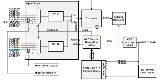
    //Select VREFLO internal connection on B5
    ADC_enableVoltRefLoConv(obj->adcHandle);

    //Select channel B5 for all SOC
    HAL_AdcCalChanSelect(handle, ADC_SocChanNumber_B5);

    //Apply artificial offset (+80) to account for a negative offset that may reside in the ADC core
    ADC_setOffTrim(obj->adcHandle, 80);

    //Capture ADC conversion on VREFLO
    AdcConvMean = HAL_AdcCalConversion(handle);

    //Set offtrim register with new value (i.e remove artical offset (+80) and create a two's compliment of the offset error)
    ADC_setOffTrim(obj->adcHandle, 80 - AdcConvMean);

    //Select external ADCIN5 input pin on B5
    ADC_disableVoltRefLoConv(obj->adcHandle);

    return;
    } // end of HAL_AdcOffsetSelfCal() function

  • Chris Lightcap said:
    such as in the function HAL_AdcOffsetSelfCal, the ADC input B5 is used as a voltage reference. In our board, this input actually corresponds to an analog hall sensor input that is being used as a trigger. Should this instead be referenced to one of our current sensor signals? 

    From SPRUH18 Figure 8-1

      //Select VREFLO internal connection on B5
      ADC_enableVoltRefLoConv(obj->adcHandle);

      //Select channel B5 for all SOC
      HAL_AdcCalChanSelect(handle, ADC_SocChanNumber_B5);

    we are attaching the internal B5 channel to VREFLO input for calibration

    Chris Lightcap said:
    Are there other places in hal.c or elsewhere in motorware that I may need to update my GPIO or ADC pins? I see that the temperature compensation function in hal.c also uses a specific ADC pin.

    I don't think so

    Chris Lightcap said:

    Also, in our configuration, we're using 2 current signals from the DRV8303 chip and 1 current signal from an external op amp. But I noticed when testing the dev kit, that based on this circuit, the current signals from the DRV chip have an inverting output, where the current signals from the op amps are non-inverting. Since we copied this schematic, I believe we may need to flip the sign of the phase B and C current sense signals. What's the best way to account for this change in polarity in motorware? I see in section 5.2.2.2 there is an example using negative feedback where they advise setting the bias in the function DRV_updateAdcBias, shown below. Should I set 

    bias += OFFSET_getOffset(obj->offsetHandle_I[cnt]);

    for phase A, and then 

    bias -= OFFSET_getOffset(obj->offsetHandle_I[cnt]);

    for phases B and C?

    Yes, you'll need to take care of proper polarity....wouldn't it be easier to flip the OPA polarity so they are all the same?  That way you don't have to handle a single channel with a different polarity in the bias?

    Also, it's not a huge deal, but if you update the HW I would recommend using the DRV device PGAs for A and B phase and the external OPA for Phase C.  This is what we did for the BOOSTXL-DRV8301 design.  The A and B values are used more often so it is better if they go through more similar circuits.

  • Thank you again for your quick feedback. One other potential problem that I found is that we're sampling an additional 4 analog input channels, based on the EPWM1 trigger, such that

    ADC_setSocChanNumber(obj->adcHandle,ADC_SocNumber_8,ADC_SocChanNumber_A5);
    ADC_setSocTrigSrc(obj->adcHandle,ADC_SocNumber_8,ADC_SocTrigSrc_EPWM1_ADCSOCA); 
    ADC_setSocSampleDelay(obj->adcHandle,ADC_SocNumber_8,ADC_SocSampleDelay_9_cycles);

    However I found in the HAL motorware document, that it should instead be triggered from ADC_Int1TriggersSOC, for example

    ADC_setSocChanNumber(obj->adcHandle,ADC_SocNumber_8,ADC_SocChanNumber_A5);

    ADC_setSocTrigSrc(obj->adcHandle,ADC_SocNumber_8,ADC_Int1TriggersSOC);

    ADC_setSocSampleDelay(obj->adcHandle,ADC_SocNumber_8,ADC_SocSampleDelay_9_cycles);

    ADC_setSocChanNumber(obj->adcHandle,ADC_SocNumber_9,ADC_SocChanNumber_B5);
    ADC_setSocTrigSrc(obj->adcHandle,ADC_SocNumber_9,ADC_Int1TriggersSOC);
    ADC_setSocSampleDelay(obj->adcHandle,ADC_SocNumber_9,ADC_SocSampleDelay_9_cycles);

    ADC_setSocChanNumber(obj->adcHandle,ADC_SocNumber_10,ADC_SocChanNumber_B6);
    ADC_setSocTrigSrc(obj->adcHandle,ADC_SocNumber_10,ADC_Int1TriggersSOC);
    ADC_setSocSampleDelay(obj->adcHandle,ADC_SocNumber_10,ADC_SocSampleDelay_9_cycles);

    ADC_setSocChanNumber(obj->adcHandle,ADC_SocNumber_11,ADC_SocChanNumber_A6);
    ADC_setSocTrigSrc(obj->adcHandle,ADC_SocNumber_11,ADC_Int1TriggersSOC);
    ADC_setSocSampleDelay(obj->adcHandle,ADC_SocNumber_11,ADC_SocSampleDelay_9_cycles);

    However, when I set to trigger based on ADC_Int1, then my analog voltages are never updated. It seems that the interrupt is never being called, but I can see in my main function that the ADC interrupts are enabled. Are there any changes I need to make to ensure that this interrupt is enabled? The measured voltage remains constant at startup, so perhaps it is sampling initially but not updating every period.

    Any thoughts? I'm concerned that this may be related to a larger problem.

  • One other issue that we're seeing is that the estimated current from the example projects, for instance 5f, shows a much lower current than that measured across a shunt resistor with a scope. Applying a steady load to the motor, we're observing 4 - 5 amps in software (from Is_A), but are only measuring rougly 12% of that on our shunt resistor connected in series to our power supply, roughly 0.5 amps. Would you expect this large of a discrepancy in the estimated value? Besides the USER_IQ_FULL_SCALE_CURRENT_A and USER_ADC_FULL_SCALE_CURRENT_A, how is this value scaled?

    Another thing to note, is that when applying an increasing load to our motor, we observe that the estimated current drops to 0 (see attached image). It almost seems that its an overflow or saturation problem with this value. Any thoughts?

    Thanks,

    Chris

  • On the ADC topic this is pretty strange.  I thought it was that the INT wasn't enabled correctly, but it should be done in the following function:

    HAL_enableAdcInts

    ADC_enableInt(obj->adcHandle, ADC_IntNumber_1);

    all of your SocNumber_1 - 7 are all being executed and motor functions correct?  You just aren't getting any of your other values?

    have you updated

    HAL_readAdcData

    to actually read these values?

    Regarding current going to 0 under load, this is the Is_A value?  Is your Iq_A going to 0 at the same time?

  • Yes all SocNumbers1-7 are being executed correctly and the motor functions properly (although weren't limited in torque). The ADCs are not being updated while running the program. Could it be that there isn't sufficient time to trigger this interrupt?

    The Iq_A is roughly 15-20amps and the Id_A is very small, less than 1 amp, but neither are zero.

  • Hi Chris,

    Is it possible that one of the additional SOCs that are supposed to be triggered by ADCINT1 are also the trigger source of ADCINT1?

    ADCINT1 is configured to fire based on the end of conversion of some SOC.  Typically this is the last conversion, so that once the interrupt is entered all the results are ready.  If you have updated the source of ADCINT1 to be one of SOC8+ and you also want SOC8+ to be triggered by ADCINT1, then they will never trigger (alternately, if you software trigger them, they will never stop converting continuously without intervention because they will keep re-triggering themselves).

    Whether or not this is the problem, it is probably better to trigger all the SOCs off of the ePWM trigger instead of triggering some SOCs off of the ePWM, then triggering more conversions based on the end of some conversion in the first set.

  • Hi Devin,

    Thanks for the response. It seems the interrupt source is being set in three different places in the project

    In setupAdcs it is set as follows:

    // configure the interrupt sources
    ADC_disableInt(obj->adcHandle,ADC_IntNumber_1);
    ADC_setIntMode(obj->adcHandle,ADC_IntNumber_1,ADC_IntMode_ClearFlag);
    ADC_setIntSrc(obj->adcHandle,ADC_IntNumber_1,ADC_IntSrc_EOC7);

    while in HAL_OscTempComp, it is set but then clears as follows:

    // connect ADCINT1 to EOC0
    ADC_setIntSrc(obj->adcHandle, ADC_IntNumber_1, ADC_IntSrc_EOC0);

    // clear ADCINT1 flag
    ADC_clearIntFlag(obj->adcHandle, ADC_IntNumber_1);

    // enable ADCINT1
    ADC_enableInt(obj->adcHandle, ADC_IntNumber_1);

    // force start of conversion on SOC0
    ADC_setSocFrc(obj->adcHandle, ADC_SocFrc_0);

    // wait for end of conversion
    while (ADC_getIntFlag(obj->adcHandle, ADC_IntNumber_1) == 0){}

    // clear ADCINT1 flag
    ADC_clearIntFlag(obj->adcHandle, ADC_IntNumber_1);

    and then finally in HAL_AdcCalConversion it is set as the following:

    // Setup ADCINT1 and ADCINT2 trigger source
    ADC_setIntSrc(obj->adcHandle, ADC_IntNumber_1, ADC_IntSrc_EOC6);
    ADC_setIntSrc(obj->adcHandle, ADC_IntNumber_2, ADC_IntSrc_EOC14);

    The HAL motorware documentation recommended using a separate different trigger so that it wouldn't interfere with PMW timing. Is this the best practice?

    On other note, do you have any suggestions why I am seeing such a disparity between my estimated and actual motor currents? And why my 'Is_A' estimated current would be driven to zero at times?

    Thanks,

    Chris

  • One other question that just came up is how is the ADC_SocSampleDelay selected. In the HAL motorware documentation is shows ADC_SocSampleDelay_7_cycles where the sample project for my dev kit has ADC_SocSampleDelay_9_cycles. Should this be tuned based on PWM timing or hardware specs?

    Thanks,

    Chris

  • Going a little deeper, I notice that there is an oscillator temperature compensation function which is pulling from analog input A5 for the dev kit. Is this being called anywhere in the project? We have a different signal connected to analog input A5.

    Thanks,

    Chris

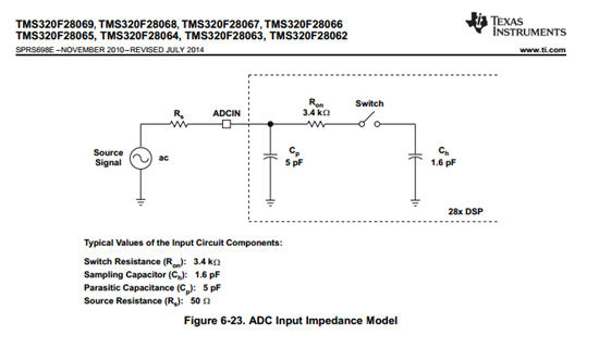
  • S+H duration is chosen based on external hardware.  The signal source driving the ADC input should be able to charge Ch to within the desired accuracy (typically better than 1/2 LSB) of its final value during the S+H window. With 50 ohm Rs, minimum S+H of 7 cycles can certainly be used, but a higher source impedance may require a longer S+H duration.


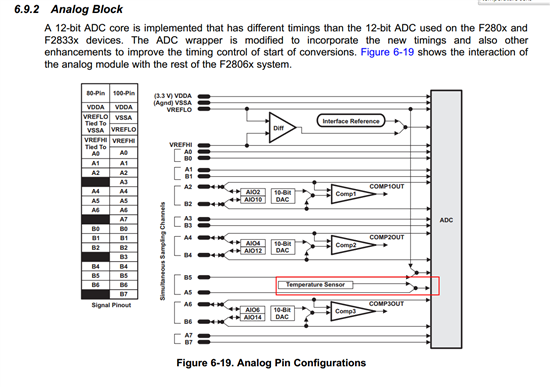
    The temperature sensor is available as an internal connection on channel A5.  When enabled, it ignores what is externally on A5:

    As far as the triggering, using ADCINT1 isn't really much different from using the ePWM from a timing perspective (below is assuming you use all the extra SOCs):

    ePWM1A triggering SOC0 to SOC15 

    ePWM1A triggering SOC0 to SOC7, SOC7 triggers ADCINT1, which triggers SOC8 through SOC15

    If you want to decouple the additional signals (SOC8 through SOC15) from ePWM1A, then it is probably better to use a spare ePWM, CPU timer, or software trigger.

  • Hi Devin,

    Thanks for the feedback. Then in the case where I have a resistor divider on my voltage sense lines of 14.3K and 4.99K, then I should have a much higher S+H duration? My current sense lines are directly connected from my DRV8303 to my MCU, but the DRV chip probably has a very high input impedance. What would you recommend for a S+H in these two cases?

    I'll stick with using ePWM1A if you don't think this will make a difference in performance.

    Lastly, I'm still not understanding why we're seeing such a discrepancy between the program's estimated current and that measured from a shunt resistor. It seems that the estimate Is_A is perhaps 8-10x greater than the actual current from my supply. How is this value calculated? Is this a peak current? Perhaps I should increase my S+H duration so that I don't measure the current transients when opening and closing the FETs. I have an extremely low inductance and low resistance motor, so there can be large current transients at these transition times.

    Since I'm coming nowhere close to the max current available from my supply, should I increase the max current parameter in my user.h file to increase my output torque. At this point, I'm seeing very poor torque performance, but I believe it's because the program believes it is seeing 5A when in reality its only 0.5A.

    Thanks again for your time.

    Chris

    Thanks,

    Chris

  • Chris Lightcap said:
    It seems that the estimate Is_A is perhaps 8-10x greater than the actual current from my supply. How is this value calculated? Is this a peak current?

    This is the current through the motor (based on sqrt(Iq^2 + Id^2), which is based on when you sample the currents (during low-side on events).  But you must remember that you aren't applying the full DC bus during these events because you are PWM'ing the voltage, so only a smaller voltage is applied (unless you are at high modulation).

    Your Is_A will be < power supply amp, until your reach high modulation (high average duty cycle).

    To get a closer value you could calculate power

    Is_A * Vbus * (Vs / 1.3333) = Power for the motor, where Vs is a per unit value corresponding to % of Vbus (up to 1.3333) being applied

    This power + some losses should be closer to your Vbus * Bus Current.

  • Chris Lightcap said:
    should I increase the max current parameter in my user.h file to increase my output torque. At this point, I'm seeing very poor torque performance,

    What I think happens is that a customer reads a current from a motor’s name plate, which is usually specified in RMS, and they set USER_MOTOR_MAX_CURRENT = name plate current.


    What you need to do is to set USER_MOTOR_MAX_CURRENT to the absolute maximum current of the motor as a peak.


    Just to give you an idea, take a look at a typical datasheet: http://anaheimautomation.com/manuals/brushless/L010228%20-%20BLY17%20Series%20Product%20Sheet.pdf


    For the first motor: BLY171S-15V-8000


    It shows the rated current is: 2.2A, but considering the torque constant of 1.98 oz-in/A, with a limit of 2.2A you can only develop 2.2*1.98 = 4.356 oz-in. However, the peak torque spec is 14 oz-in! so you would never get this peak torque with a max current of 2.2A. What you need to do is specify the max peak current to generate the peak torque. So the max current of this motor would be the peak torque over the constant, so 14 / 1.98 = 7.07 A, instead of 2.2A.