This thread has been locked.

If you have a related question, please click the "Ask a related question" button in the top right corner. The newly created question will be automatically linked to this question.

Critical error occurs when Using InstaSPIN-MOTION

Other Parts Discussed in Thread: MOTORWARE, DRV8301

Hello,

Sorry to bother you with a new question.


I have spent time trying to identify a three-phase asynchronous motor with InstaSPIN-MOTION, DRV8301-HC-EVM and F28069 ISO controlCARD.


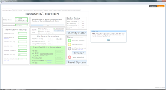
Every time a same critical error occurs on the GUI like this:


So I can’t start my project. I wonder if there is something wrong with my parameters of Identification Settings and Control Timing ? Could you give me some advice ?


Motor parameters:


Model:            ZPJ0.75-90S-4

Rated Power:       750W

Rated frequency:    90Hz

Rated voltage:      16V

Rated current:      43A

Rated speed:       2600r/min

Rated torque:       2.5N.m


Thanks very much,


Brant Zheng.

  • Hello,

    Just to confirm, is it F28069MISO that you use? Insta-SPIN Motion need M version.

    Best regards,

    Maria

  • thank you for your attention !

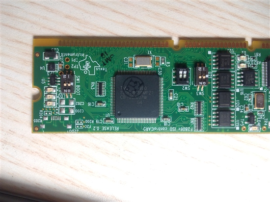
    I'm sure that I'm using the  F28069MISO. Here is the picture

    Best regards,

    Brant Zheng

  • OK.

    Is LD4 and LD1 ON before you start your GUI?

    Do you have CCS installed on your PC?

    Can you try 'Test Connection' from CCS and what is the result?

    Best regards,

    Maria

  • I will say that once you get pas this emulation error you are still going to have issues with this high current ACI motor

    1. The InstaSPIN GUI you are using is "frozen" and should be thought of as a demo. It uses code from over 2 yrs ago. It will work for many motors, but not most ACI and not when the voltage or current range is outside the norm of the kit. You need to use the MotorWare projects for most motors.

    2. There are still some outstanding issues with the Motor ID portion of ACI motors. We fixed most of them in MotorWare _12 (we are now on _13) but there are still some challenges with some HV motors, and most LV high current motors won't ID correctly.  We have it on our list to fix, so I'm hoping it gets done this year.


  • Hello Maria,

    LD1 and LD4 are both ON before I start my GUI.

    I ran a project ,and the connection between CCS and controlCARD is OK.

    Perhaps the current of my ACIM is too high for this kit ?

    Thank you for your help !

    Brant Zheng

  • Hello Brant Zheng,

    I just notice that you use DRV8301 EVM. As I know this kit is not for controlling ACI motor, this is for BLDC and PMSM. Do you have BLDC or PMSM motor to test the kit?

    "The DRV8301-HC-C2-KIT is a motor control evaluation kit for spinning three phase brushless DC and brushless AC (BLAC) - often referred to as permanent magnet synchronous (PMSM)" - from website (http://www.ti.com/tool/drv8301-hc-c2-kit)

    And like Chris said, this GUI is rather old.

    So better you try the project labs from Motorware, start from Motor Identification (lab2b).

    In this case, we will know whether your motor can be identified well by Motorware or not.

    Good luck!

    Best regards,

    Maria

  • The DRV8301 EVM is appropriate for running any three phase motor, induction included.  It is rated - when using MotorWare projects - for +/-40A maximum, so it should be absolutely fine for no-load motor bring up and nearly full load testing (assuming appropriate power supply).


    As mentioned though the ACI Motor ID process is still not "Instant".  It is more complicated than the PM motors and it really requires you to know the rated flux of the motor.  If you use a value too large your magnetizing current will grow too large and then it either loses control during ID process (at Id rated or Rated Flux) or the values it finds don't produce appropriate torque.

    With high current motors the current control is even more difficult so stability during the ID process is very critical.

    But, if you know enough about your ACI motor - if you have a good enough set of design parameters - all the parameters can be found.

    what do you know about this motor?


  • ChrisClearman said:
    The DRV8301 EVM is appropriate for running any three phase motor, induction included. 

    Hello Chris, thanks for the confirmation!

    Best regards,

    Maria

  • Hello Maria,

    Thank you for your advice!

    I learn and followed the "InstaSPIN Projects and Labs User’s Guide" ,and ran the lab01 ,then ran the lab02 from Motorware.

    It succeed that My BLDC got its parameter identification and achieved speed control. it worked.

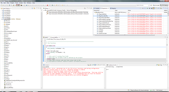
    But when I put on my High Current ACIM, the same error came up again on CCS like this: 

    And the CCS showd "Target is not connected"

    Best regards,

    Brant Zheng

  • Hello Chris,


    I'm  so happy to be able to get your attention!


    And I think your suggestion is very meaningful to me.


    I ran the lab01 and lab02a  with Motorware. And I succeed with my BLDC , but failed with my high current ACIM during the measuring of FLUX. And then the connection between CCS and the kit failed.

    So far I only know some of the basic parameters of the motor. As you mentioned the ACI Motor ID process is still not "Instant".  So if I get more detailed parameters of the ACIM, such as the rated flux, Rs, Ls_d, Ls_q, magnetizing current, Rr, by consulting my motor supplier or other ways, then is it possible that I fill in the ready-made parameters into user.h directly and continue the project  without ID identifying process ? In this way, can I use the DRV8301 EVM to achieve control of the High Current ACIM ?


    Thank you for your help!


    Best regards,


    Brant Zheng

  • Brant Zheng said:
    if I get more detailed parameters of the ACIM, such as the rated flux, Rs, Ls_d, Ls_q, magnetizing current, Rr, by consulting my motor supplier or other ways, then is it possible that I fill in the ready-made parameters into user.h directly and continue the project  without ID identifying process ?

    If you can provide into user.h these values for your ACI motor you can bypass motor ID and it will run flawlessly.  .

    #define USER_MOTOR_NUM_POLE_PAIRS       (2)
    #define USER_MOTOR_Rr                   (0.4)
    #define USER_MOTOR_Rs                   (0.6)
    #define USER_MOTOR_Ls_d                 (0.001557)
    #define USER_MOTOR_Ls_q                 (USER_MOTOR_Ls_d)
    #define USER_MOTOR_MAGNETIZING_CURRENT  (0.89)
    #define USER_MOTOR_RES_EST_CURRENT      (1.0)
    #define USER_MOTOR_MAX_CURRENT          (1.5)


    There is nothing wrong with InstaSPIN-FOC control of ACI motors....we only struggle still with some motors (and very few are "instant") in identifying the values.  The main issue is around finding the appropriate magnetizing current, and this is usually caused by an incorrect (too large) value being used for the rated_flux.  With high current motors there is the added difficulty of the current being harder to control / needing good stability during this "open loop" ID process.  The gains of our current controllers don't appear to be ideal for high current ACIs during ID.  In the project you can actually go change the values that are getting set. There is currently a scale factor of 0.25 used for the current Kp gains.  You can try setting these higher to see if it helps with the control stability.

    You will notice this control stability issue - if you have it - during the transition of IdRated to RatedFlux and then during Ls estimation.


  • Brant Zheng said:

    I learn and followed the "InstaSPIN Projects and Labs User’s Guide" ,and ran the lab01 ,then ran the lab02 from Motorware.

    It succeed that My BLDC got its parameter identification and achieved speed control. it worked.

    But when I put on my High Current ACIM, the same error came up again on CCS like this: 

    You're saying that you can connect a BLDC motor, connect with CCS and run proj_lab02 successfully?

    But if you then switch to an ACI motor you can't even connect with CCS?

    That doesn't make any sense at all....the motor that is connected can't make any difference to JTAG connectivity.


    From the error it looks like you "rudely" disconnected while the MCU was still running in real-time mode.  Try disconnecting from the debugger and then relaunching the debug session.


  • Hello Chris,


    Thank you for your advice!


    I spent a few days trying and testing repeatedly but it still failed in the ID process of my ACIM. Now I am currently considering these issues:


    1: The note of “Rr” and “Rs” show that “Identified phase to neutral in a Y equivalent circuit” , and my ACIM is a “delta” connected motor. Is this technique only for Y-connected motors?


    2: As you mentioned that I can bypass motor ID and it will run flawlessly if I have these values for my ACIM. But these values, such as Ls_d, Ls_q, are not the basic parameters which can be provided by my motor supplier. So is there some other way I can get these values? Like using basic parameters and some formulas to calculate these values?


    Best regards.


    Brant Zheng

  • Brant Zheng said:

    1: The note of “Rr” and “Rs” show that “Identified phase to neutral in a Y equivalent circuit” , and my ACIM is a “delta” connected motor. Is this technique only for Y-connected motors?

    No, InstaSPIN doesn't care how the motor is connected. It would only change how you translate the line-neutral values we calculate into line-line valus for your type of motor.

    Brant Zheng said:

    2: As you mentioned that I can bypass motor ID and it will run flawlessly if I have these values for my ACIM. But these values, such as Ls_d, Ls_q, are not the basic parameters which can be provided by my motor supplier. So is there some other way I can get these values? Like using basic parameters and some formulas to calculate these values?

    Two ways.

    1. You notice that Rs was already found in the GUI....it's probably correct. 0.015 ohm.  Rr is typically about 70% of this value I find, so try setting Rr = 0.01 ohm.  Rs / Ls is typically designed about 2x the top Hz of the motor (when designed well). So if you want to take a guess, you can try

    Ls = Rs / (2 * Rated_Hz)

    In your GUI .jpg I'm not sure if the 200 Hz value is actually the top speed, but assuming it is, you can try

    Ls = 0.000375

    The harder value is the magnetizing current.  You can start with a value of about half the rated current.

    I am pretty confident the motor will run no load pretty well.  Then you can do some load/torque capability testing. If you aren't generating enough torque you can increaes the magnetizing current.

    2. If you have enough nameplate data you can calculate all needed values.  I've seen this on high voltage ACI, but very rarely on low voltage which tend to be very custom

    http://e2e.ti.com/support/microcontrollers/c2000/f/902/t/318299.aspx


  • Hello Chris,


    I ran the lab03b. With your help, my ACIM finally ran no load pretty well! Thank you so much!

    And now I’m going to do some load/torque capability testing.


    But there is still a problem that the connection between CCS 6.0.0 and F28069x_ISO_controlCARD breaks "rudely" after I set the Flag_Run_Identify to “1” while the MCU is still running in real-time mode. Here is the picture. And it can not be reconnected anyway.


    So that I can’t see the operating parameters from the “expressions” and change the value I want. Could you help me solve this problem?


    Best regards!


    Brant Zheng. 

  • i would guess noise from the AC/DC or the motor itself.

    To test, if you can try providing high voltage DC directly insteady of AC/DC and see if that solves it entirely.

    Either way, if your motor has a ground wire, use it. Any sort of additional grounding (even on the USB cable) can help.


  • Hello Chris,


    Your guess is quite correct. My High-power switching power supply generates a lot of noise. It goes well when I use the battery on a forklift as my power supply. Thank you again!


    And what confuse me is the values of ‘ADC current offsets’ and ‘ADC voltage offsets’. The default values of the offsets of drv8301kit :


    I_A_offset    (0.9939797521)

    I_B_offset    (1.014363647)

    I_C_offset    (1.005615234)


    V_A_offset    (0.5020679235)

    V_B_offset    (0.4977650046)

    V_C_offset    (0.4986107945)


    How are these values calculated? What’s the relationship between the values and hardware?


    Best regards,


    Brant Zheng 

  • see Ch 6.5.2 of SPRUHJ1