This thread has been locked.

If you have a related question, please click the "Ask a related question" button in the top right corner. The newly created question will be automatically linked to this question.

DRV8301-69M - Low Speed Algorithms - Torque control - Generation mode

Other Parts Discussed in Thread: MOTORWARE, CONTROLSUITE, DRV8301

Dear all,

I want to use the DRV8301-69M development kit to evaluate the sensorless control of a PMSM motor in generation mode. An external speed is applied to the motor under test and a reverse break torque is applied to the driving motor. I have modified example 4 "Torque Mode" from the motorware labs. The DC bus is extended with a chopper and break resistors to absorb the regenerated energy.

The principle works fine for the moment, but I have to solve some issues:

1. Low speed: When running at low speed (< ~1RPM), it's not possible any more to control the motor properly. Especially at higher torques. I disabled already the forced angle, which improved already the results, since the driving motor is controlled in speed and we want to break with constant torque.

On the forum I saw TI is working on algorithms (eSMO, HFI) to improve low and zero speed control. This is available in the controlsuite. Will this become available in the motorware and if yes, do you have a timing for this?

2. When I request a constant Iq (= constant torque since Lq = Ld) to the motor under test and the applied driving motor speed is varying, I can see the torque increases with an increasing speed (Torque increases ~1Nm if speed varies from 1 to 10 rps) while the estimated torque is more or less constant over speed. [measured without Rs online calibration]

3. At higher speeds and higher torques, the speed and torque estimations becomes instable. [No Rs online recalibration]

4. I tried already to enable the Rs online compensation to compensate the Rs resistance but I'm not able to get proper values from the online compensation. The online Rs value oscillates around a certain value (which influences the estimated torque). Is it possible the online measurement doesn't work that good for non-silent motors (Lq not equal to Ld)?

Motor specs:

  • Stall torque 9.7Nm
  • Torque constant 0.388Nm
  • BEMF constant 23.6V
  • Ld = Lq = 0.6mH
  • Poles 32

Thanks in advance for your inputs!

Best Regards 3s

  • 3sRol said:
    Low speed: When running at low speed (< ~1RPM), it's not possible any more to control the motor properly.

    Correct, there is a lower threshold on frequency that FAST will continue to operate. Because your motor has such large Bemf and large poles you are able to achieve a very low mechanical speed (1 RPM = 3.75 Hz).  With this motor and proper voltage and current scaling I believe you should be able to go a bit lower, but there will always be a limit as FAST relies on Bemf (which only occurs with rotor movement).

    3sRol said:
    On the forum I saw TI is working on algorithms (eSMO, HFI) to improve low and zero speed control. This is available in the controlsuite. Will this become available in the motorware and if yes, do you have a timing for this?

    We are engaged with some early adopter customers on this topic now: InstaSPIN-FOC + IPD_HFI.  We are going to release this in stages with the first hopefully coming in the next release of MotorWare _14 (this is probably going to be January due to some HW delays on a new kit we are releasing).  The IPD_HFI is not "instant" and requires some manual tuning using a scope, etc. We are working on documentation to make it easier to use. 

    3sRol said:
    2. When I request a constant Iq (= constant torque since Lq = Ld) to the motor under test and the applied driving motor speed is varying, I can see the torque increases with an increasing speed (Torque increases ~1Nm if speed varies from 1 to 10 rps) while the estimated torque is more or less constant over speed. [measured without Rs online calibration]

    Which torque are you talking about that increases? Which measurement?  I would expect the torque of the driving motor (the estimated torque from FAST) to stay constant with a given Iq_Ref that is low enough for the external motor to still maintain a speed.

    3sRol said:
    3. At higher speeds and higher torques, the speed and torque estimations becomes instable. [No Rs online recalibration]

    What is the ID'd flux of this motor in V/Hz?  I am guessing that you are saturating the Bus voltage and IQ_VOLTAGE measurement of this kit.  What value are you using for IQ_VOLTAGE in user?

    3sRol said:
    4. I tried already to enable the Rs online compensation to compensate the Rs resistance but I'm not able to get proper values from the online compensation. The online Rs value oscillates around a certain value (which influences the estimated torque). Is it possible the online measurement doesn't work that good for non-silent motors (Lq not equal to Ld)?

    This could be due to #3 or some other configuration issue.  No, it works just fine for salient and non-salient. 

  • Mike,

    you may want to read this post about an experiment I did today.

    http://e2e.ti.com/support/microcontrollers/c2000/f/902/t/369447.aspx

    I did see the torque measurement change for the MOTOR, but the LOAD machine is very stable (sign changes) with the same speed being controlled on the MOTOR.  If the sign of the speed of the MOTOR changes then the torque from the LOAD will change (in one case it is working against the motor, in the other it is helping the motor).

    On #3, I was able to duplicate some of this, but it is because I don't have enough power.  I'm using an 18Vdc bus with a motor that can easily be used on 60Vbus and do double the torque I'm able to produce at this low 18V.

    Even though I can go ~3100 RPM no load @ 18V, as soon as my load went past 1.3A the max speed would start to drop.  But it was still very stable, and when load was removed it would regain ~31000 RPM.  With a speed command of just 2000 RPM I could load to nearly 4.3A before the speed dropped slightly, but much more load and it dropped much lower (~500 RPM) and with enough load the motor would finally reverse direction.  This is completely expected / normal.

  • Dear Chris,

    Thanks for your detailed answer. Let me explain it a little more…

    1.       First of all, there was a typo in my initial post. I can go to ~1 RPS. But the lower speed threshold depends on the applied torque. For higher torques, the lower speed threshold is higher.

     Does it mean, we need another hardware platform to use IPD_HFI?

     2.       One of the tests I have done:

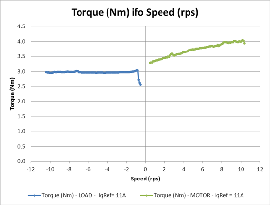
    -          The LOAD (motor + TI InstaSPIN = Devices under test) is driven in torque mode with a constant torque. For example the IqRef = 11A as in the attached graph.

    -          The MOTOR is driven in speed control, but able to deliver the needed torques. The MOTOR is ramping up and down from 0.5RPS (30RPM) to 10.4RPS (625RPM).

    -          The collected data, estimated torque and estimated speed from the LOAD and torque and speed from the MOTOR is averaged and torque is plotted in function of speed for both the LOAD (blue) and the MOTOR (green). The graph for IqRef = 11A is attached.

    From the attached graph [TifoS_11A], it can be seen the estimated LOAD torque is constant over speed. The MOTOR torque increases with increasing speed.

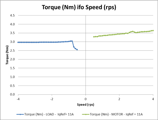
    From the more detailed graph [TifoS_11A_detail], it can be seen the estimated LOAD  torque drops down at 1 RPS.

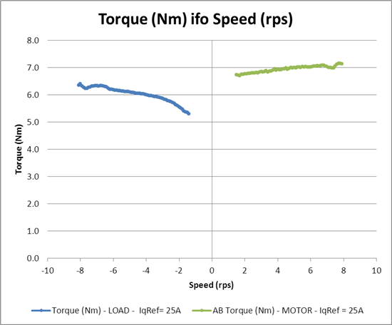
    For the higher torques (IqRef = 25A) the estimated LOAD torque is no longer constant over speed. The estimated torque increases with increasing speed. [TifoS_25A]

    3.       This are some parameters from my user.h:

    -          USER_MOTOR_RATED_FLUX                      (0.07143413)      V/Hz

    -          USER_IQ_FULL_SCALE_VOLTAGE_V       (48.0)                    V

    -          USER_ADC_FULL_SCALE_VOLTAGE_V   (66.32)                  V [66.32 drv8301_revd voltage scaling]

    So you are suggesting to use a higher DC-bus voltage? Or can I change something in the user.h header file to improve the behavior?

    4.       I have done an additional test:

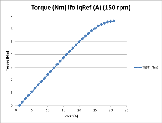
    -          The MOTOR is driven in speed control at a constant speed (150rpm in the attached graph).

    -          The LOAD is driven in torque control with different IqRef set points.

    -          The estimated LOAD torque is plotted in function of the IqRef set point.

     From the attached graph [TifoIq], it can be seen the estimated LOAD torque is linear for lower IqRef set points. If I calculate the torque constant from the data points with IqRef < 20A, I can find the torque constant from the motor datasheet.

    On the other hand the estimated LOAD torque behaves not linear for IqRef > 20A. Do you have an explanation for this phenomena?

    Thanks in advance for your support!

    Best regards,

    3s