This thread has been locked.

If you have a related question, please click the "Ask a related question" button in the top right corner. The newly created question will be automatically linked to this question.

Having Trouble With Lab 12 using Encoder in HV KIT

Other Parts Discussed in Thread: MOTORWARE, LAUNCHXL-F28069M, BOOSTXL-DRV8301

Sir,

Motor Used :  Motor Power TC80-2.8-21 model Having

                         Rated Speed = 3000 @230VAC,                 Rated Torque = 2.6Nm ,

                         Rated Current = 3Arms, and Encoder PPR = 2000.


My Setting,


#define USER_MOTOR_TYPE                                       MOTOR_Type_Pm
#define USER_MOTOR_NUM_POLE_PAIRS             (4)
#define USER_MOTOR_Rr                                              (NULL) 
#define USER_MOTOR_Rs                                            (0.7422892) 
#define USER_MOTOR_Ls_d                                         (0.003110148) 
#define USER_MOTOR_Ls_q                                          (0.003110148) 
#define USER_MOTOR_RATED_FLUX                           (0.3917434) 
#define USER_MOTOR_MAGNETIZING_CURRENT   (NULL) 
#define USER_MOTOR_RES_EST_CURRENT           (1.0) 
#define USER_MOTOR_IND_EST_CURRENT             (-1.0)
#define USER_MOTOR_MAX_CURRENT                      (1.00) 
#define USER_MOTOR_FLUX_EST_FREQ_Hz            (20.0)
 #define USER_MOTOR_ENCODER_LINES                 (2000.0) 
#define USER_MOTOR_MAX_SPEED_KRPM                (3.0)
#define USER_SYSTEM_INERTIA                                    (0.05456888676) 
#define USER_SYSTEM_FRICTION                                 (0.05014914274) 

I am using HV kit , In lab 12 I connected the encoder appropriately with the kit and have tested this by 

variable "st_obj.vel.conv.Pos_mrev" which comes around '1.0' on one full manual rotation of motor shaft. And even Added a long variable in program "EncCounts " which i m monitoring in watch window, which come around 8000 on full manual rotation of motor shaft.

EncCounts = ENC_getRawEncoderCounts(encHandle);   //Used in watch window  to debug.

Now the problem is ,

When  "gMotorVars.Flag_enableSys" & "gMotorVars.Flag_Run_Identify" is set to 1.

I monitored the encoder counts its varies even though the motor shaft is stationery.

Then Motor velocity run with varing speed (Sometime it run with high RMP and Some times in Low RPM) and stops in between speeds. Even though in this whole process my RefSpeed is 100RPM.

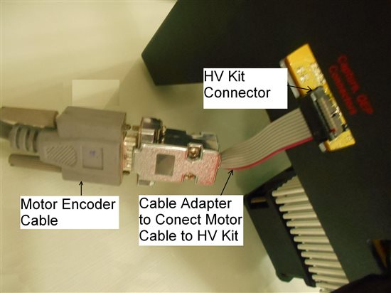
Please (Below image) have a look at cable adapter made to connect motor encoder cable with the HV Kit.

Motor Encoder Cable is shileded but the adapter here is a Bus Strip which is not shielded. Will this create a problem???

If this is the problem ...How to Cable the motor connector to KIt  to eliminate Noise??

  • Bipin,

    This can be a very difficult problem.  You mentioned that your cable is shielded, is that shield connected to the ground on the HVKit?  It is important to make sure that any shielding is connected to a ground.

    Also you can look at using the input qualification on the 28069M chip.  There is information in spruh18 that should help with setting this up.  This is something we are looking into for future MotorWare releases.

  • Thank you Very Much Sir...

    Solution of connecting Earth Too Ground Made a drastic change...Now MY motor is running Smoothly...

    One more Question, At RPM greater than 50 My Motor runs smooth..but at low RPM like 10 or so..i have a coggling like moment of motor shaft..Why is this so ??..As it is sensored  it is expected to run Smooth in every RPM isnt it??

  • Bipin,

    I'm glad that resolved your issue.  Encoder noise can be very tricky.

    The issue you are running into is the minimum resolution problem with encoders.  In your system, assuming you are running the speed loop at 1kHz, the minimum resolution can be found by 1 / (4 * 2000) * 1000 * 60 = 7.5rpm.  So the speed resolution of the encoder is only 7.5rpm, which makes it difficult to get great control much slower than that.

    There are a couple of ways to help with this:

    1. Adjust SpinTAC Velocity Control Bandwidth.  A larger bandwidth will help make slow speed control smoother.  

    2. The speed feedback method only uses pulse counting, where over a fixed period of time the number of encoder pulses is counted and that determines the speed.  There is an alternate method called pulse timing where the time in-between pulses is measured, and this give you a very good low speed estimate.  You can write an algorithm that uses this measure for speed at low speeds and uses pulse counting for a measure at high speeds.  This would give you a much better speed estimate.

    3. in SpinTAC Position Convert, there is a low-pass filter that can help with these resolution issues.  You can adjust the tuning of this filter in order to more heavily filter the speed feedback.

  • Sir,

    Good After noon !!!

    My Motor run as per the Ref Speed in Lab 12. So my Encoder feed back is working Fine

    In Lab 13a, I am not able to get good torque on motor !

    My motor holds the zero position when i m trying to rotate manually in either direction. I even got error 2002 and 1013, where 1013 is due to i exceeded the bandwidth to saturation and 2002 is position error which is due to exceeding of Max Position Error .

    In my normal servo drive i really cant move the shaft by hand when the motor is in servo hold or zero position. but  in my HV Kit (Lab 13a) I am able to move the shaft in one complete rotation without much Torque but when i leave the shaft the shaft come back to zero position.

    How can i improve the torque of my motor??

  • Bipin,

    In looking at your previously posted settings it seems like the maximum torque of your motor is set to 1 amp.  This seems like a very low value.  We use this value to determine the maximum output of the speed or position regulator.  So if you increase this setting it will send more current into your motor and allow it to hold more torque.

  • Sir,

    Increasing the Max Current has really increased the torque...Thank you

    Now whenever i m running the lab13a, sometimes its work fine ...sometimes it gives an error ID 2002 on power on, But when i rotate the shaft of motor manually to minimize the error till the error ID is 0, at this point  it regains the torque again...

    Why is that it shows error code 2002 sometime when i connect my PC to The Kit??  

  • Bipin,

    The error code 2002 means that the amount of error in the position controller has exceeded the maximum allowable position error.  It is a feature that is designed to improve the safety of the system.  It can get into this condition if the motor is rotated when the motor is rotated without the code running on the mcu.  It should not be a common condition.

  • Sir,

    I M Working On Lab 13C.

    I Have Set Following Configuration for Back And Fro Movement of Motion....

    STPOSPLAN_addCfgState(stObj->posPlanHandle, 0, 0, 2000L); // StateIdx0: A
    STPOSPLAN_addCfgState(stObj->posPlanHandle, 2, 0, 0L); // StateIdx1: B
    STPOSPLAN_addCfgState(stObj->posPlanHandle, -2, 0, 0L); // StateIdx2: C

    STPOSPLAN_addCfgTran(stObj->posPlanHandle, STATE_A, STATE_B, ST_COND_NC, 0, 0, _IQ(1.0 * ST_SPEED_PU_PER_KRPM), _IQ(3.1), _IQ(3.1), _IQ20(3)); // From StateA to StateB

    STPOSPLAN_addCfgTran(stObj->posPlanHandle, STATE_B, STATE_C, ST_COND_NC, 0, 0, _IQ(3.0 * ST_SPEED_PU_PER_KRPM), _IQ(4.1), _IQ(4.1), _IQ20(3)); // From StateB to StateC


    STPOSPLAN_addCfgTran(stObj->posPlanHandle, STATE_C, STATE_B, ST_COND_NC, 0, 0, _IQ(3.0 * ST_SPEED_PU_PER_KRPM), _IQ(4.1), _IQ(4.1), _IQ20(3)); // From StateC to StateA

    Have Observed that after few minute of movement the motion Dampens... and the motion stops...and again it the motion starts......

    But at this movement some times  error ID Displays : POsition error (2002 ) and some time no error is displayed when the motor stops 

    Why is it So??

    If i Increase the gMotorVars.SpinTAC.PosCtlBwScale value ....Then i don't get the required Position Control at High Speed.

    Even I M Not Getting a precise stop OR abrupt stop at its position. It moves some what ahead of its position

    ( This Is At gMotorVars.SpinTAC.PosCtlBwScale = 1.5)

    My motor is of 5000 RPM @ 230V.......

    Rated Torque = 2.6Nm ,

    Rated Current = 3Arms, and Encoder PPR = 2000.

    I M Using Trapezoidal Cur for the above configuration,.

  • Sir,

    I Have One More Quarry, How is the RPM and Current Scaled....?

  • Bipin,

    I would guess that the system isn't tuned properly.  If you are running your motor with nothing coupled to it BwScale of 1.5 is quite low.  Did you use lab 12a or 5c to determine the inertia of your system?  

    Bipin Patil said:

    If i Increase the gMotorVars.SpinTAC.PosCtlBwScale value ....Then i don't get the required Position Control at High Speed.

    What do you mean by this?

    I think you should increase the BwScale of the system.

    RPM is scaled by (USER_IQ_FULL_SCALE_FREQ_Hz * 60) / USER_MOTOR_NUM_POLE_PAIRS.

    Current is scaled by USER_IQ_FULL_SCALE_CURRENT_A.

  • Sir,

    1) I thave done  the tuning of the motor  once again but still my motor stops after a while.....without any error ID

     2) I M Going To patch My Velocity loop (Calculated using Encoder Counts) with its torque command converted to IQ 24 Format and given to Iqreference in CTRL_setIq_ref_pu(ctrlHandle, iqReference)

    I m Using  In Lab 12 for above mention change....Is there any Cumulative Encoder Value That I Can get so the i can feed the Velocity Loop.

    Now i m getting my Encoder Counts from ENC_getRawEncoderCounts(encHandle); Which is 0-8000

  • Bipin,

    You can get a cumulative motor position from the SpinTAC Position Converter module.  This output will be in the units of mechanical revolution and not in the units of encoder counts.  I've attached a document that explains how the position signal from this works.

    0027.SpinTAC_Position_Move_Rollover.pdf

    You can combine the Pos_mrev signal with the RollOver signal in order to get an absolute position of the motor.

  • Sir,

    Thank You!!

    My Velocity Loop is Working Now..

    I want now to add a 1 Millisec Timer Interrupt in the Code....Please Guide me with the Procedure to add Interrupt..

  • Bipin,

    I'm glad to hear that the velocity loop is working.

    For help with the timer interrupt, take a look at this document: 4527.motorware_hal_tutorial.pdf

    It is from MotorWare 13 and provided in the docs/tutorials directory.

  • Sir,

    Thank You ,,,,,,,I have Successfully Set up the Timer Interrupt...

    1) Can I get a GUI Composer Installation for Code Composer 6..... I have downloaded GUI Composer Setup but is not Working...It Gives an Error During Installation....

    2) Can we Put Delfino Control Card In HV-Kit. ... At present We Are using Piccolo Control Card

  • Bipin, 1. There should be a GUI Composer add-in for CCS v6. You should be able to install it via CCS. I'm not very familiar with GUI Composer. 2. You can put a delfino control card into the HV kit but you will not be able to use the MotorWare software for the delfino card.
  • Sir,

    1) We are planning to use TMS320F2807x in Our drive...Want To Know whether InstaSpin will be availabe in  DSP TMS320F2807x....

    If No ..Then when will this take place sir.

    2) While trying to run GUI Composer from Motorware...I am Getting An Error " Unable to Locate GUI Composer Server to Launch this Application".How to resolve??

    3)Pardon Me Sir, But  Where can i get the actual Current Consumed By The Motor (In Arms). How to Convert It To Arms.

  • Bipin,

    Bipin Patil said:
    1) We are planning to use TMS320F2807x in Our drive...Want To Know whether InstaSpin will be availabe in  DSP TMS320F2807x....

    InstaSPIN-FOC & -MOTION will not be available on the TMS320F2807x platform.  But the SpinTAC Motion Control Suite without the reference FOC will be available on that chip.  So you can still use SpinTAC but will need to provide you own FOC code.

    Bipin Patil said:
    2) While trying to run GUI Composer from Motorware...I am Getting An Error " Unable to Locate GUI Composer Server to Launch this Application".How to resolve??

    I"m not sure how to resolve this issue.  Hopefully a TIer can respond or try posting this issue on the CCS E2E forum: http://e2e.ti.com/support/development_tools/code_composer_studio/f/81.aspx

    Bipin Patil said:
    3)Pardon Me Sir, But  Where can i get the actual Current Consumed By The Motor (In Arms). How to Convert It To Arms.

    You should be able to calculate the length of the Is vector in order to get the amount of current flowing into the motor.  Note that this will be different than the amount of current seen on the DC bus.  Here is a code snippit from lab 10b that calculates the length of this vector.  Note this does not calculate RMS, but you should be able to convert this into RMS.

    // read Id and Iq vectors in amps
    gMotorVars.Id_A = _IQmpy(CTRL_getId_in_pu(ctrlHandle), _IQ(USER_IQ_FULL_SCALE_CURRENT_A));
    gMotorVars.Iq_A = _IQmpy(CTRL_getIq_in_pu(ctrlHandle), _IQ(USER_IQ_FULL_SCALE_CURRENT_A));
    
    // calculate vector Is in amps
    gMotorVars.Is_A = _IQsqrt(_IQmpy(gMotorVars.Id_A, gMotorVars.Id_A) + _IQmpy(gMotorVars.Iq_A, gMotorVars.Iq_A));
    

  • Hello,

    Where is this formula found? - the formula you gave to find the minimum speed loop resolution: 1 / (4 * 2000) * 1000 * 60 = 7.5rpm

    I ask because I am having a problem at low speed. I am running the Motorware labs on a LaunchXL-F28069M Launchpad (rev 1.1) with one BoostXL-DRV8301 Rev B on J5. The motor is a Anaheim Automation BLY171D-24V-4000-1000SI-05 with a connected encoder (ENC-E21000197-HI).

    I'm at lab 12b, SpinTAC Sensored Speed Control.

    At low speeds (anything less than 1000 RPM) the motor is not spinning smoothly. The problem can be amplified by slowing down to 100 or 50 RPM (gMotorVars.SpeedRef_krpm = 0.09999996424 or 0.04999995232) and placing some blue tape on the motor shaft, and you can clearly see that the motor turns about 1/4 turn and almost stops, then turns another 1/4 turn and almost stops, etc. Viewing one encoder channel on the oscilloscope you can see (as expected) that it is a cyclic behavior of speeding up and slowing down.

    I calculated the minimum resolution using the formula from your post, substituting my encoder's 1000 lines as follows:

    1 / (4 * 1000) * 1000 * 60 = 15 RPM.

    So when running sensored, at speeds as low as 15 RPM it should turn at a nice consistent speed, but it's not doing that even at 50 or 100 RPM. This leads me to believe that I missed something along the way. What should I look at?

  • I created that formula. :) It looks at the minimum possible counts in terms of revolutions (1/(4*2000)) divided by the samplin frequency and converting seconds into minutes. Hence it gives you minimum possible resolution. What is the bandwidth for the SpinTAC controller? Did you identify the inertia in lab 12a?
  • I identified the inertia in lab 12a. I could have made a mistake somewhere along the way, or any number of things could be wrong. I'm trying to narrow it down...

    When I ran lab 12a I copied gMotorVars.SpinTAC.InertiaEstimate_Aperkrpm into USER_SYSTEM_INERTIA and gMotorVars.SpinTAC.FrictionEstimate_Aperkrpm into USER_SYSTEM_FRICTION. This was then compiled into lab 12b.

    There are also values from earlier labs, both InstaSPIN-FOC labs and InstaSPIN-MOTION labs, that I have accumulated in my user_j5.h file as a result of going through the labs. There are two different user_j5.h files depending on whether it's a InstaSPIN-FOC or InstaSPIN-MOTION lab; so I took care to copy things over using WinMerge.

    #define I_A_offset (0.8265658021)
    #define I_B_offset (0.8283884525)
    #define I_C_offset (0.8276902437)

    #define V_A_offset (0.4953790307)
    #define V_B_offset (0.4939436316)
    #define V_C_offset (0.4948484898)

    .
    .
    .

    #define USER_MOTOR Anaheim_BLY171D

    .
    .
    .

    #elif (USER_MOTOR == Anaheim_BLY171D)
    #define USER_MOTOR_TYPE MOTOR_Type_Pm
    #define USER_MOTOR_NUM_POLE_PAIRS (4)
    #define USER_MOTOR_Rr (0.0)
    #define USER_MOTOR_Rs (0.821521044)
    #define USER_MOTOR_Ls_d (0.00128526473)
    #define USER_MOTOR_Ls_q (0.00128526473)
    #define USER_MOTOR_RATED_FLUX (0.032984741)
    #define USER_MOTOR_MAGNETIZING_CURRENT (NULL)
    #define USER_MOTOR_RES_EST_CURRENT (1.0)
    #define USER_MOTOR_IND_EST_CURRENT (-1.0)
    #define USER_MOTOR_MAX_CURRENT (3.0)
    #define USER_MOTOR_FLUX_EST_FREQ_Hz (20.0)
    #define USER_MOTOR_ENCODER_LINES (1000.0)
    #define USER_MOTOR_MAX_SPEED_KRPM (4.0)
    #define USER_SYSTEM_INERTIA (0.02723675966)
    #define USER_SYSTEM_FRICTION (0.1404172182)

    Anaheim_BLY171D was not originally an option; I added it.

    All of my prior work has been with brush motors. I am new to FOC, so I don't know if any of the above values seem unreasonable.
  • All of your values seem reasonable.

    I think the issue is that your speed loop bandwidth is too low. You can adjust it via gMotorVars.SpinTAC.VelCtlBw_radps and when you find a good value set it in USER_SYSTEM_BANDWIDTH in the user_j5.h file.
  • You're absolutely right. I increased bandwidth to 100. I went as high as 150 and tried going higher still but somewhere around 160 it starts to buzz and at 170 or so it starts jumping all over the place :-) So I turned it back down to 100. It runs much, much better than before. Yes, I forgot to tune the ONE parameter that needs to be tuned. :-)

    But... it's running sensored with a 1000 line encoder and according to your formula, I should be able to go as slow as 15 RPM. So I'm trying to do just that.

    Coming from the brush world, where you can expect perfectly smooth consistent motion at slow speeds, I am trying to determine what to expect with BLDC, FOC, SpinTAC, etc.

    With this bandwidth setting (and with the higher settings I tried), the shaft speed still fluctuates. It's not exaggerated as it was before, when each shaft rotation happened in four lunges. Now, it's like the motor is taking many many little mini-steps. It turns all the time, it doesn't quite stop, but just by looking at it, I can see the "steps," if that makes any sense. When looking at an encoder channel on the oscilloscope, the width of the pulses is all over the place, as can be expected when the speed is constantly fluctuating.

    By the way, this isn't just at 15 RPM. This happens at 30 RPM, 60 RPM, etc., though obviously the slower I go, the more pronounced it is.

    So at this point (being that I come from the brush world and I'm new to this type of control), can this be improved upon?
  • That formula represents the minimum resolution of the speed feedback.  So your speed sensor resolution is 15rpm.  Which means that when trying to control at 15rpm the speed feedback will be quantized to steps of 15rpm.  This will make it difficult to control the motor speed at 15rpm since the feedback will be jumping by 100%.

    I would expect this behavior with any control system since it is in the feedback path and has little to do with the underlying torque control mechanism.  It is dep

    There are a couple different things that can be done in order to reduce this effect.

    1. Increase the filter coefficient for SpinTAC Position Convert.  You can do this in the spintac_velocity.h file in the function  ST_setupPosConv with the call STPOSCONV_setLowPassFilterTime_tick(obj->posConvHandle, 3) where the 3 is the number of sample ticks to use in the filter coefficient calculation. 

    2. The feedback calculation method used by MotorWare is called pulse counting.  This method has trouble with low speed resolution but is excellent at high speed resolution.  In this method the number of encoder pulses over a fixed sample time is considered.  You can also use a method call pulse timing where the time in between pulses is used to calculate the speed.  This method has excellent low speed resolution but has trouble with high speeds.  You can combine these two methods so that the speed calculation will use pulse timing at low speeds and pulse counting at high speeds.  

    3. You could consider using position control running in an emulated velocity mode.  Lab 13e implements this behavior.  Using this lab I've been able to smoothly spin a motor with 500 encoder lines at 1 rpm.

    Even in brush control, the quality of the speed control will still come down to the feedback sensor.