This thread has been locked.

If you have a related question, please click the "Ask a related question" button in the top right corner. The newly created question will be automatically linked to this question.

Difficulty Tuning Motor

Other Parts Discussed in Thread: TMDSHVMTRINSPIN, MOTORWARE

Hi,

I am having trouble tuning the VLM33J servo motor I am testing.   I’m using lab 12b and running sensored.   Using SpinTAC the load regulation is not as good compared to the same motor with a commercial servo drive.

Inertia was estimated in Lab12a.    The inertia estimate of 0.872 was within 28% of the calculated value of 0.680.   I also noticed that different Kp_Idq settings give slightly different inertia estimates.   I mention this because it may play into my problem.

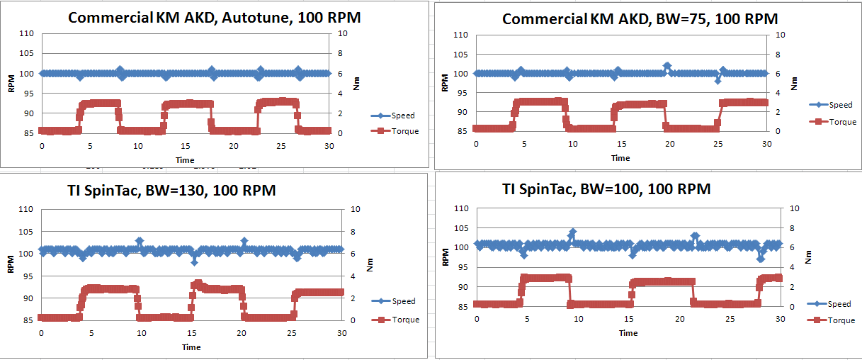
Using Lab 12b with two bandwidths (100 and 130) the data below was taken comparing SpinTAC to a commercial servo drive.   The same motor, encoder, and  load setup was used.     When the load is changed (0 to 3 Nm) the commercial drive’s speed has less disturbance.  The commercial drive auto tuned and slider tuned are the top two graphs, SpinTAC with BW of 130 and 100 on the bottom graphs.  Hopefully you can see the speed changes are much more on the bottom graphs.

I've tried other bandwidth settings.   With lower bandwidths the speed disturbances are even greater, and with higher bandwidths the speed changes are smaller, but running at higher speeds (500 RPM, 1K RPM) the motor is noisier and the system vibrates more.

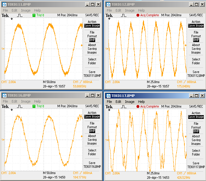
These tests were done with Kp_Idq set to 0.40.   I've tried other proportional gains but this seems to give the best performance.    Below are the current signals for the commercial drive and SpinTAC.    The commercial drive at 100 RPM and 500 RPM are at the top.   The SpinTAC/TI drive at 100 RPM and 500 RPM are on the bottom.   At 100 RPM the two look similar, but the SpinTAC signal at 500 RPM looks bad.  This is certainly causing some of the vibration.


 I am not sure of how to better tune the motor.   At zero speed and bandwidth of 130 with no load, if you take the shaft of the motor and rotate it 90 degrees, it seems fairly tight and snaps back to position with little oscillation.   So it feels tuned OK.  But for the same setup, with the commercial drive the shaft is harder to turn and stiffer.   I don’t understand this because looking at the current waveform while doing this test, both waveforms look similar.   Why would 6 Amps of current feel weaker with TI than the commercial drive.

Please provide any suggestions on how to better tune this motor.

Thanks.


  • I've sent this over to LineStream for their comments.

    The thing that jumps out to me is the noise of the currents on the SpinTAC tests.

    I am guessing you are using a TI EVM for this test, while the off the shelf drive has perhaps a higher quality design (especially in regards to current sense, it may even be using hall based phase current measurements).

  • Hi Chris,
    I am using the TI HV Kit (TMDSHVMTRINSPIN).

    Also this morning I verified the motor moves (aligns) during initialization. MOTOR_RES_EST_CURRENT is set to 3 Amps. I thought maybe you would ask about this setting.

    Thanks.
  • Thanks for the great amount of data. This really helps paint a clear picture of what is going on in your system. I agree with Chris that the current sensing for the COTS drive is probably of higher quality than the TI EVM. This is going to have a pretty big impact.

    Additionally what update rate are you running the speed loop? In MotorWare the default speed loop update rate is 1kHz, in many of these drives they will run the speed loop faster than this. This will give them better speed performance than what we provide out of the box with MotorWare. You can adjust the speed loop update rate by modifying USER_NUM_CTRL_TICKS_PER_SPEED_TICK in the user.h file.

    Also some of these drives don't actually run in speed mode, they will run in a modified position mode where the profile generation is continuously updating the position reference in order to emulate a velocity control. We provide an example of this is lab 13e.
  • Adam makes another good point. Servo systems are typically running much faster control loops. You may see 16 KHz current loops with 8 KHz velocity and position. This combined with significant HW differences (especially in regards to current sense but perhaps even in encoder noise) probably are the biggest contributors. It's not exactly an apples to apples comparison.
  • Chris, Adam.  Thanks for the quick replies.

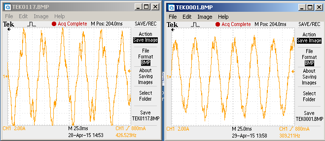
    I changed the control loop from 1 kHz to 3 kHz and the current signal got better.    Then I was able to increase the BW to 150 without vibration/noise and the speed deviations with torque changes were less.    Still not as tight speed control as the commercial drive, but better than the original data I posted.

    This is the current signal with the speed loop at 1 kHz (left) compared to 3 KHz (right).

    Still not perfectly sinusoidal with the faster speed loop, but better.    Increasing the speed loop even more (5 kHz) seemed to have no effect.

    I've noticed the SpeedQEP_rpm bobbles around a few rpm in the debugger.     I haven't dug into the handling of the encoder readings yet.   Is there filtering on this value, or would some small amount of filtering help if there is noise (as suggested) on the encoder readings?   Or the other possibility is the speed loop is causing the bobble.

    I'm still concerned at not having a better shaped current signal.

    Thanks again.

  • current waveforms still don't look very good.
    are you confident in the motor parameters identified? while you are using the encoder for angle feedback the Rs and Ls are still being used for the current controller gains.
  • Chris.

    I think the motor is correctly identified.   Lab 2a gives fairly consistent results (today Rs= 0.476, Ls= 0.00150, Flux= 0.7123).   Based on the VLM33J nameplate the calculated values are Rs= 0.49, Ls= .00156, Flux = 0.684.   So the estimated vs. calculated values are close.

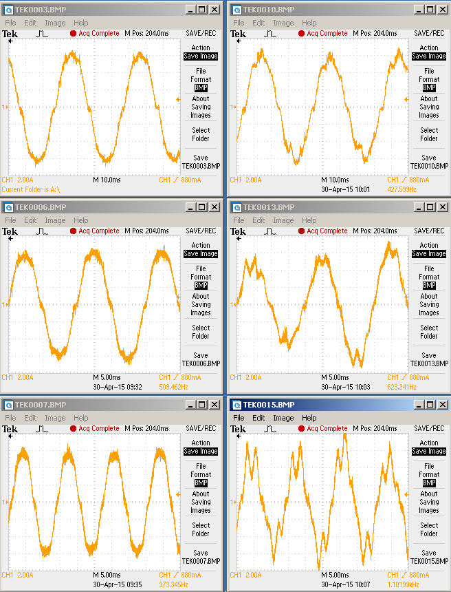
    In previous posts I compared the current waveform between the commercial drive and HV Kit, and with a faster speed loop I indicated the current signal looked better and motor ran smoother.  This was only at 500 RPM.  Today I compared the TI Kit sensorless (lab 5b) to sensored (lab 12b).   See below current waveforms for 500, 1K, 1.5K RPM with sensorless on the left and sensored on the right.    Sensorless current shape is much better.  Both had the same current gains Kp = 0.4, Ki=.02.   Sensorless had speed Kp = 12, Ki= 0.3.    Sensored had BW= 150.

    Since the same current gains are used sensorless and sensored, and sensorless looks OK, it would seem the current gains are OK.  I also mentioned earlier that the motor moves slightly before starting, so I think the encoder alignment is working.

    Do you think this points back to noise on the encoder when used with the HV kit, but not present with the commercial drive?

    Or a SpinTAC problem?

    Thanks.

  • I would use project 12 and compare the angle from the estimator and the spintac angle converter.

    They should be very close. My guess is they are not  

    Certainly something is wrong with the encoder path.

  • The encoder signal coming out of the spintac angle converter is only used for position control.  The encoder signal used for FOC control comes from the ENC module directly.  So there could be issues in the encoder signal, it won't be caused by SpinTAC.

  • Chris, Adam.
    I verified the encoder signals are electrically clean. The edges look fast and the quadrature relationship looks good.

    I was able to capture and plot the QEP and Estimator angles. They are indeed very close, although I don't know how much error between the two can be expected. I might look at this closer.

    But during all this testing, I noticed that sometimes at high speeds the current signal looks distorted and other times it looks OK, depending on the start up. I'm back to thinking the motor is not aligning correctly during the Rs re-calibration, even though I see it physically move during this state.

    I've tried further increasing USER_MOTOR_RES_EST_CURRENT with no seeming change. Even though the value is set to 4 Amps or 5 Amps, during the Rs calibration the current on the coils only gets to ~2A. Should I see the coil current get to the ...EST_CURRENT level? Can you point me to the code that sets this current during alignment? I don' see "maxCurrent_resEst" being used.

    Thanks.
  • RLetizia said:
    Can you point me to the code that sets this current during alignment? I don' see "maxCurrent_resEst" being used.

    This is part of the trajectory / state machine code that is kept private in the library or ROM.

    How high speed are you talking about? What frequency in Hz?

  • The last oscilloscope images I posted were for sensorless vs. sensored at 500, 1K & 1.5K RPM . With a 6 pole motor this is 25, 50, & 75 Hz.
    With sensored and BW=150, the 1K and 1.5K RPM current signals look poor, both compared to sensorless and a commercial drive sensored.

    I posted last that the current signals sometimes looks a little better depending on the startup. Also I've seen the signals looks much better if I lower the BW from 150 to 140, or even better at 130. But the problem with the lower BW settings are with torque disturbances the speed varies more (see original posts showing speed changes), and with the lower BW the zero speed holding torque is poor. For example with BW=130 at zero speed I can twist the motor shaft and the return torque does not seem as high as it should, compared to the commercial drive.

    I can't find a problem with the encoder signals. It really looks like difficulty tuning SpinTAC. BW = 150 and the current signals get distorted. BW = 140, 130 and the speed regulation with torque disturbance is poor and holding torque weak.
  • Comparing the control performance of SpinTAC running on evaluation hardware against a commercial drive isn't really a fair comparison.

    The commercial drive has a huge number or advantages in that comparison. Not only do they have better sensing circuitry, but they have done a lot of work to compensate for the deadtime of their power devices.

    The point to compare is not strictly the performance of SpinTAC against the commercial drive. You also need to factor in the ease of use when working with this solution as you develop your own motor drive.

    Additionally these drives "velocity" control is really position control in disguise. We have an example of that type of technology in lab 13e. I would recommend that you use that lab to do this comparison.