This thread has been locked.

If you have a related question, please click the "Ask a related question" button in the top right corner. The newly created question will be automatically linked to this question.

Preserve Const Speed with Variable Voltage and Stop the Motor as quick as possible

Other Parts Discussed in Thread: DRV8301

Hi everyone,

I'm triyng to duplicate and then to improve an old driver for a BLDC motor with DRV8301 kit (F2806x Iso Control Card).

The system must work with a battery power supply (range 50.4V full charge to 33.4V low limit charge).

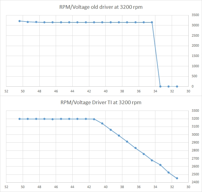
Decreasing on-line the power supply voltage to simulate the battery behavior, I found two different graph shown in photo (No load motor):

The good news is that the TI driver continues to work under 34V and in the power on from 0 speed (motor stopped) the TI driver always starts the motor in contrast to the old driver that under 40V in unable to start the motor.

The bad news is that, if the motor runs at 3200 rpm and the power supply voltage decreases, under 41V the speed decreases drastically.

I know that decreasing Vbus will always decrease the max speed but I see that the old driver absorbs gradually more current during the decreasing of power supply voltage to have almost the same power and to perform the target speed.

There is a way to perform the same thing also in the TI driver?

I also must stop the motor as quick as possible (under 3 seconds with all kind of load for safety conditions); now I'm using the HAL_disablePwm(halHandle) to stop the motor, there is another way more fast and safe?

Thanks in advice and sorry for my bad english, 

Matteo

  • " (range 50.4V full charge to 33.4V low limit charge)."
    I'd be careful of using DRV8301 for this solution. It is really not meant to be used in battery applications above about 42V I think. I know in 48V systems they like to have more voltage headroom. If the DRV8301 sees more than 60V it will be damaged.

    first thing to solve your problem
    1. is Vbus Compensation enabled or not?
    2. you may want to increase your modulation. It is likely the drive you are comparing to uses 6-step commutation, meaning it can apply more voltage to the inverter. This is the difference between 34-41 V. proj_lab10 shows how to increase the modulation value to apply more voltage.
    3. I believe this will solve most if not all of the problem, but if it does not you could then add your own logic to enable some field weakening (proj_lab09) to maintain the speed.

    "I also must stop the motor as quick as possible (under 3 seconds with all kind of load for safety conditions); now I'm using the HAL_disablePwm(halHandle) to stop the motor, there is another way more fast and safe?"

    this will just "coast" the motor. If you want to stop it sooner you can drive it to 0 speed, but be careful as this is when the Vbus will get loaded and likely have voltages > Vbus nominal. There are also HW solutions to do this by shorting all high or low sides and dumping in the energy into a brake resistor (this is a common approach for example in washing machine applications).
  • Thanks Chris for your answer,

    the first problem is near to be solved, with the overmodulation and the Vbus compensation disabled the target speed is preserved until 37 V (under the system is a little bit unstable).

    In the second problem I drive the motor to 0 speed (or at least I think I did - maybe I didn't follow the right procedure, can you explain a little bit more?) but the stop is to slow.

    If I do the right thing, then I'd think to force to gnd all the three phase of the motor (close for example the Q7, Q8, Q9 MOS in the 515502~1.pdf schematic, how can I do this? with the HAL_writeDacData ()/HAL_writePwmData() function?Which values can I use to do this?

    Thanks Again

    Matteo

  • "In the second problem I drive the motor to 0 speed (or at least I think I did - maybe I didn't follow the right procedure, can you explain a little bit more?) but the stop is to slow."

    if you are in speed control mode you can set a 0 KRPM command with a high enough acceleration to meet your requirements (Assuming the motor can actually stop that fast). Be aware of the Bemf being generated by the motor at your maximum speed (max_speed_Hz * flux in Volts per Hz) to be sure that voltage will not damage your inverter. As I mentioned, in large Bemf applications they often use brake resistors to dump the energy when they need to make an emergency stop.

    "If I do the right thing, then I'd think to force to gnd all the three phase of the motor (close for example the Q7, Q8, Q9 MOS in the 515502~1.pdf schematic, how can I do this? with the HAL_writeDacData ()/HAL_writePwmData() function?Which values can I use to do this?"

    yes, this is also an option to brake the inverter, switching on all high or low side. You will need to review the ePWM user's guide and set-up the HAL_write_Pwm function appropriately, instead of what is coming from the CTRL system.
  • Thanks Again,

    I try to implement this last solution but, for now, my solution doesn't work very well:
    When I wan't to stop the motor, the firmware bypass the CTRL function (CTRL_run() and CTRL_setup()) and when the speed decrease under 1500 RPM I set all three variables gPwmData.Tabc.value[0,1,2] to _IQ(0.0) and then I use the HAL_writePwmData() to force all three phase to low level.

    What I see at the oscilloscope is that: in the first part of braking there are floating phases (right behavior because I use HAL_disablePwm()); in the second part (when the speed is under 1500 RPM) I see all three phases not at low level but oscillating between high and low level (all three with the same timing --> I think that the driver switch on alternately Q4,Q5,Q6 (High level MOS) and Q7,Q8,Q9 (Low level MOS)).

    I achieve a good braking effect but I'd like to force to low level all three phases for all the braking time; I know that I'am doing something wrong but I don't understand the error. Any suggestions?

    Another question: setting to 0% the duty cycle, do I obtain the same results?In affermative case, which variable do I change to work directly on the duty cycle?

    Matteo

  • Matteo,
    your questions are out of my area of knowledge. I've sent this along to someone else to answer.
  • Hi Chris,

    I solve the active braking problem; I modified the HAL_writePwmData() in HAL_writePwmMOD() and I use it when, in the braking sequence, the speed goes under 2000 RPM:

    static inline void HAL_writePwmDataMOD(HAL_Handle handle,_iq dutyCycle)

    {

    uint_least8_t cnt;

    HAL_Obj *obj = (HAL_Obj *)handle;
    PWM_Obj *pwm;
    _iq period;
    _iq value;
    uint16_t value_sat;

    for(cnt=0;cnt<3;cnt++)
    {
    pwm = (PWM_Obj *)obj->pwmHandle[cnt];
    period = (_iq)pwm->TBPRD;
    value = _IQmpy(dutyCycle, period);
    value_sat = (uint16_t)_IQsat(value, period, _IQ(0.0));

    // write the PWM data
    PWM_write_CmpA(obj->pwmHandle[cnt],value_sat);
    }

    return;
    } // end of HAL_writePwmDataMOD() function

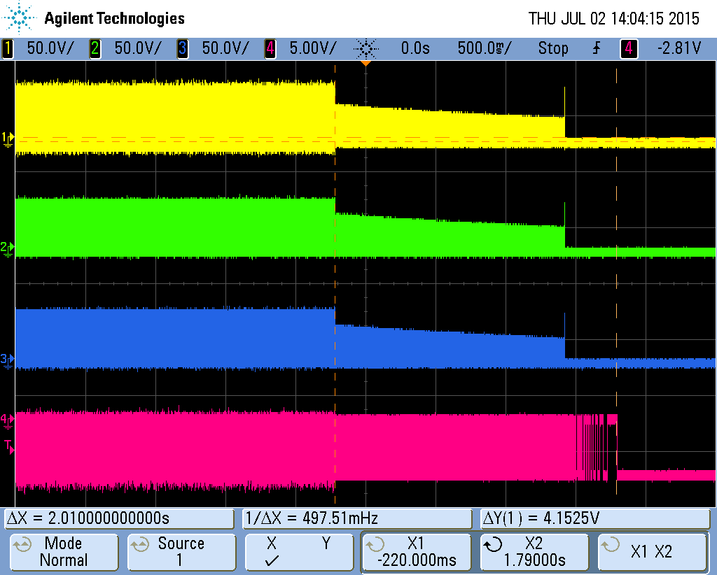
    If I set to _IQ(0.0) or _IQ(1.0) I'am able to force all three phases to low or high level; in the photo you can see the first braking part with floating phases and the second braking part with all three phases to low level

    Thanks to the purple signal that represents one of the three hall sensors monted in the motor, I can controll the effective braking time which is about 2 seconds (perfect for my security specific)

    I have now another question: Which is the maximun value for the overmodulation variable that doesn't damage the inverter and let me to obtain the best performance in terms of stability and max speed with low power supply voltage?

    I set overmodulation = _IQ(1.5) to maintain 3200 RPM in 41-31V voltage range with no load motor. Is this value too high?how can the situation change with a loaded motor?

    Thanks Again

    Matteo

  • yes, that is too high.

    if you are using proj_lab10 over-modulation (svgen_current replaces svgen) you can go up to a maximum modulation of 1.3333
    else you should limit to 1.0