This thread has been locked.

If you have a related question, please click the "Ask a related question" button in the top right corner. The newly created question will be automatically linked to this question.

Problem with phase current sensing

Hello InstaSPIN community


We are running “lab13e” with our second board based on the DRV8301-69-KIT. This second board use three hall type current sensors to measure the phase current, while the first board measure the current through the low-side MOSFET like DRV8301-69-KIT.


We took some steps to adapt to the new board with phase current measurements:


Step1: set USER_IQ_FULL_SCALE_CUEENT_A to (125.0) and set USER_ADC_FULL_SCALE_CUEENT_A to (250.0). Because the output voltage of the current sensor is 0 to 3.3V while the detected current is -125A to 125A. The bias voltage is 1.65V.


Step2: set USER_NUM_CURRENT_SENSORS to (3)


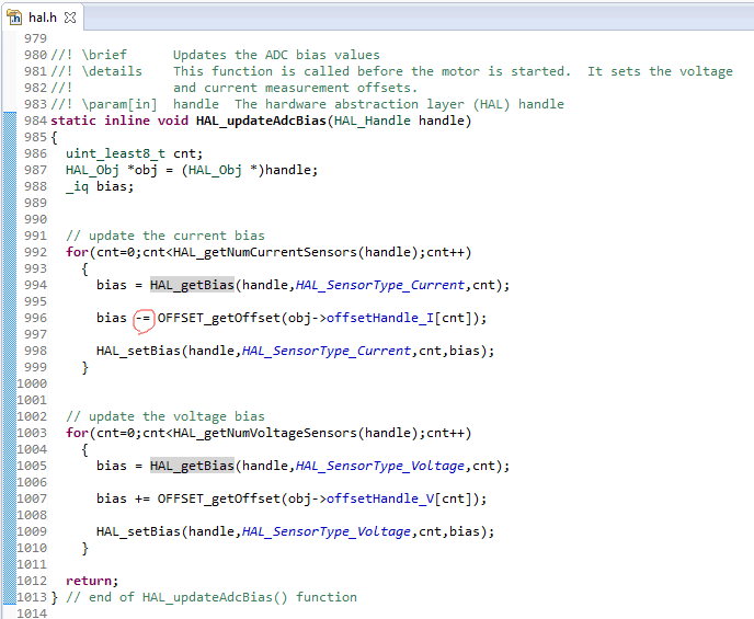
Step3: set the bias from “+” to “-” in hal.h. Because when the sink current flows through the sensor, then through the low-side MOSFET and back to GND, the sensor output is a positive incremental voltage.


Step4: configure the ADC channel in hal.c.


The problem is that when we run the “lab13e”, after the current and voltage offsets, the next normal procedure is going to hold the motor at zero speed. But actually, the board become unstable and the three-phase half bridge circuit can be burned out.


Did we miss something or did something wrong in configuration?


Any advice will be appreciated.


Best regards.


Brant Zheng.

  • 1. I assume you have actually typed these correctly USER_IQ_FULL_SCALE_CUEENT_A or it wouldn't compile

    2. I don't see that you missed anything per se

    3. when using phase current measurements you only need to use 2 (use U, V) the W is unnecessary

    4. I would use proj_lab02a or 2c to debug. Go through MotorID and make sure that the RoverL and Rs states are producing the correct magnitude of current per SPRUHJ1 User Guide

    5. What is the current of this motor? You aren't trying to run a low current motor on a 165A scaling are you?

  • Hello Chris,


    The max current of this motor is 60A.


    I  used proj_lab02a, after the current and voltage offsets, the same situation happened again when “EST_State_RoverL”. The input current of the board became abnormally high and the motor shake violently.


    This second board has the only difference that it uses phase current measurements. Our first board which use the shunt current measurement can run the motor well. 

  • I would suspect that your current measurement circuit / scaling is not correct for your board with phase current measurements. Do you have the correct sign set on your bias? are you properly scaling vs. 1.65V = 0 A, 3.3V = max A?

    do you have the measurement circuits correctly tied to the U, V, and W channels of the ADC measurement?  The order is important.

  • Hello Chris,


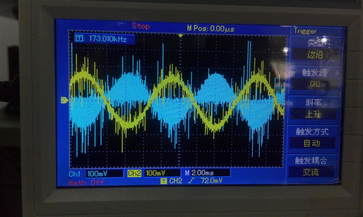
    I did a test experiment that I used the first board with shunt current measurement to run the ACIM, at the same time, I used the second board with phase current measurement to detect the phase current and the encoder. The power output part (three half-bridge circuit) of the board with phase current measurement was not welded.


    Look at this. The blue waveform represents the shunt current of phase A and the yellow waveform presents the phase current of phase A. so I’m sure that my current measurement circuit/scaling is right.


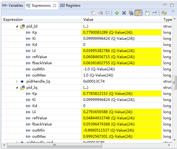
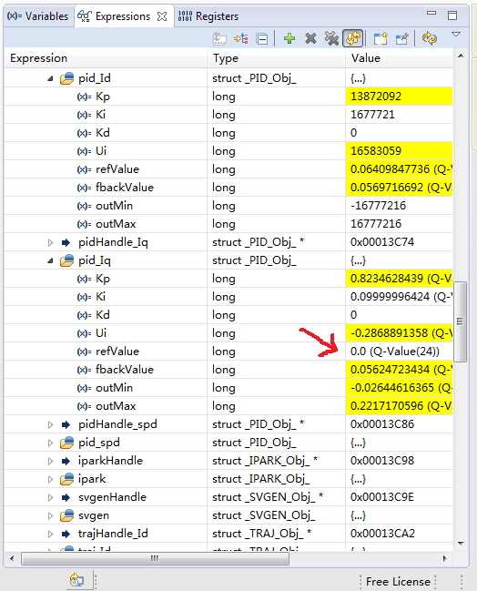
    Then I noticed that the pid_Iq.fbackValue of the two boards are very close, but the pid_Iq.refValue of the second board with phase current measurement is zero!

    The first board with shunt cunrrent measurements ↓


    the second board with phase current mesurements↓

    Now, only I changed in program is the sign on current bias and the ADC channels. 

  • did you make progress on this?
    I don't understand how you could be driving the motor with an Iq_ref of 0.0

    I wish I could be more helpful