This thread has been locked.

If you have a related question, please click the "Ask a related question" button in the top right corner. The newly created question will be automatically linked to this question.

Current sense circuit

Hi,

I built my own hardware very similar to the HVkit board. I´m using a LaunchXL F28069M as the main processor. I have something wrong with my current sense circuits. My shunt resistor are OK (or I think so). I chose the same HV Kit´s opamp and the same feedback resistors.When I put the same HV Kit´s values of USER_IQ_FULL_SCALE_CURRENT_A and USER_ADC_FULL_SCALE_CURRENT_A (as it should be as it´s the same circuit) and tried to identify the motor with the lab2B, the real DC current is much lower than the specified in USER_MOTOR_RES_EST_CURRENT. 

The measured current offsets are more or less the same as in the HV kit, so i presumed that the amplifiers are functioning correctly. There is some noise added to the current sense output amplifiers so I added a feedback capacitor and I also presume that the software averages the ADC values when measuring the DC current values. As a result of all this, the Rs values are lower than the real values, of course if I diminish IQ_FULL_SCALE and ADC_FULL_SCALE, the Rs values get closer to the real ones but It don´t think that it had any logic to make such a change.
I wonder if the low DC current values and the noise related ti the ADC resolution have anything to do with all this.
Please give a clue.
Thanks
Andrés

  • Andres,
    It's hard to debug from what you've posted. It certainly seems like there is a problem with your layout or component values. I would triple check these sections.

    referring to SPRUHJ1 Motor Identification you will see that as motor ID starts the RoverL test will use 1/2 of USER_MOTOR_RES_EST_CURRENT and then Rs test will use the full value. This is a good place to test your circuit. Yours appears to have a serious problem.

    "I also presume that the software averages the ADC values when measuring the DC current value"
    No, the software clearly is taking single samples for currents. There is no averaging.
  • Chris,

    Actually I measured the real DC current with a very cheap tester, and I obtained USER_MOTOR_RES_EST_CURRENT only changing the values of USER_IQ_FULL_SCALE_CURRENT_A (1.5) and USER_ADC_FULL_SCALE_CURRENT_A (2.9), instead of (10.0) and (19.89) respectively. I triple check the circuit and even thought there are some inaccuracies in the shunt+connection resistances, it's not reasonable such a differences. I tried and red the ADC current values:

    aldagus_I1_A[i]	= _IQmpy(gAdcData.I.value[0],_IQ(USER_IQ_FULL_SCALE_CURRENT_A));
    aldagus_I2_A[i]	= _IQmpy(gAdcData.I.value[1],_IQ(USER_IQ_FULL_SCALE_CURRENT_A));
    aldagus_I3_A[i]   	= _IQmpy(gAdcData.I.value[2],_IQ(USER_IQ_FULL_SCALE_CURRENT_A));

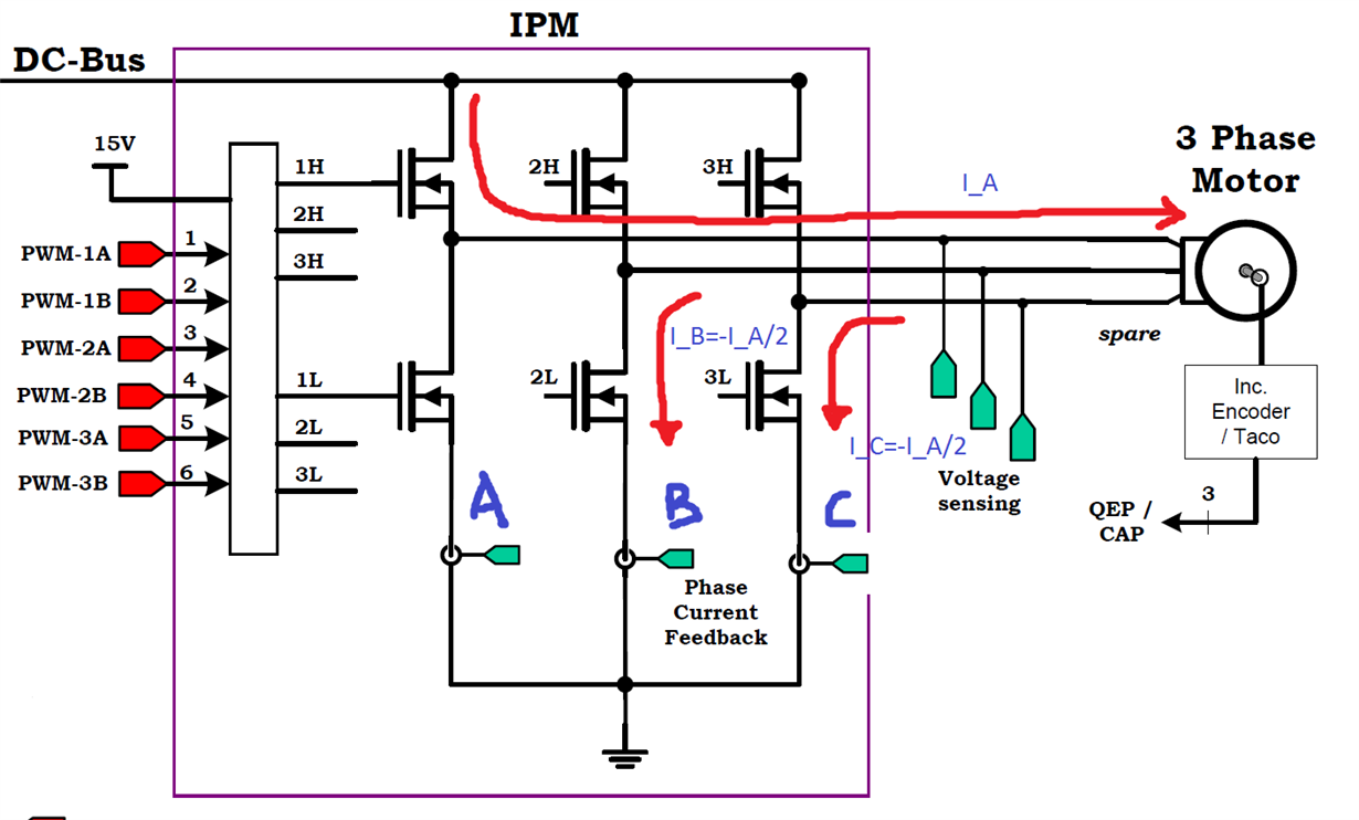
    I don't understand how the current can be measured in the u phase since it's sourced by the u phase and sinked v, w phase and the shunt resistors only measured the sinked current.

    Thanks in avance

    Andrés

  • "I obtained USER_MOTOR_RES_EST_CURRENT only changing the values of USER_IQ_FULL_SCALE_CURRENT_A (1.5) and USER_ADC_FULL_SCALE_CURRENT_A (2.9), instead of (10.0) and (19.89) respectively."

    I don't understand what you are saying.

    ADC_FULL_SCALE_CURRENT_A is set in user.h based on the scaling of the current sampling circuit. For example if the circuit is created to measure +/- 8.5A then the FULL_SCALE_CURRENT would be set to (17.0)

    The IQ_FULL_SCALE_CURRENT needs to be set to any value >= 0.5 * ADC_FULL_SCALE_CURRENT_A. so at least (8.5) and most people choose an integer number, ex: (10.0)

    These values can't change due to any other factors, they are set in user.h


    "I don't understand how the current can be measured in the u phase since it's sourced by the u phase and sinked v, w phase and the shunt resistors only measured the sinked current."

    the shunt resistors measure positive or negative current flow, and all three measurements can be taken at the same time (or consequetivily in our case). under normal sinewave modulation we are only using the current conversion from the U and V phases though. This is handled in the SVGEN functions. During over-modulation logic is used to choose the best 1 or 2 out of 3 currents to use for reconstruction.
  • I chose the same HV Kit's opamp and the same feedback resistors, when I put the same HV Kit's values:

    USER_IQ_FULL_SCALE_CURRENT_A (10.0)
    USER_ADC_FULL_SCALE_CURRENT_A (19.89)

    in the identification of the stator resistance, the real DC current injected in U phase (I measured it with a very cheap multimeter in series with the output) is much lower than the specified in:

    USER_MOTOR_RES_EST_CURRENT (0.3)

    So I changed this:

    USER_IQ_FULL_SCALE_CURRENT_A (1.5)
    USER_ADC_FULL_SCALE_CURRENT_A (2.9)

    to obtain 0.3A in the multimeter and the Rs values were correct (in comparison with HVKIT):

    #define USER_MOTOR_Rs (27.0585)

    but the Rr and Ls values obtained, are very different in comparison with HVKIT:

    #define USER_MOTOR_Rr (0.8195829)
    #define USER_MOTOR_Ls_d (7.427809e-07)

    The motor spins, but I decided to use the values measured with the HVKIT.

    #define USER_MOTOR_Rs (27.0585)
    #define USER_MOTOR_Rr (13.7835)
    #define USER_MOTOR_Ls_d (0.06810735)

    The motor spins on the lab3a. Then I tried my own plan based on the lab6d. But when the Rs recalibration is done with this last values and with

    USER_IQ_FULL_SCALE_CURRENT_A (1.5)
    USER_ADC_FULL_SCALE_CURRENT_A (2.9)

    I don't obtain a correct recalibration, the recalibrated Rs value is very different and variable. The motor doesn't spins correctly.

    I measured with a LRC meter the shunt and feedback resistors (in the HVKIT and my own board), and it certainly seems the same. The only difference between Hvkit and my board is the IGBT module, I use IRAMS10UP60A instead of PS21765.
  • there is something wrong with at least your current sampling circuit. you can't just change the FULL_SCALE values until the DC value appears to match what you think it should be.

    there is some fundamental circuit issue you need to fix. then update the USER variables appropriately per the calculation based on the circuit.
  • I replaced the shunt resistors and opamp with 3 hall allegro sensors (ACS712). I put a current probe in the U phase output.

    I changed USER_IQ_FULL_SCALE_CURRENT_A and USER_ADC_FULL_SCALE_CURRENT_A according with the hall sensor sensibility.

    In the identification of the stator resistance, the real DC current injected in U phase measured with the current probe was 0.6A, but in the hall sensor was 0.3A. Of course the Rs value is wrong.

    On the previous post I wrote this:

    I don't understand how the DC current can be measured in the u phase since it's sourced by the u phase and sinked v, w phase and the shunt resistors/hall sensors only measured the sinked current.

    In graph:

  • I see there are three options for that sensor, a +/-5A, +/-20A and +/-30A. Which one do you have? and also, please share your user.h file. Keep in mind that the value you configure in USER_ADC_FULL_SCALE_CURRENT_A should be from peak to peak, on a range from 0 to 3.3V of the ADC. which by the way, did you add a circuit that scales down the sensor output from 0-5V to 0-3.3V?
    -Jorge
  • I use +/-20A sensor and my USER_ADC_FULL_SCALE_CURRENT_A    is    (40.0)

    yes, I added a circuit that scales down the sensor

    Thanks in advance

    Andrés54285.user.h

  • Thanks.

    Looking at the datasheet of this sensor, even though it says +/-20A, that doesn't mean -20A to +20A creates 0.0V to 5V. In fact, they have a plot that shows current vs. output voltage, so -20A generates 0.5V, and +20A generates 4.5V. So 4V / 40A = 0.1V/A of sensitivity. If we extrapolate to cover the entire 5V range, this would result in:

    5V / 0.1V = 50A, so +/-25A.

    If we asume a perfect circuit that converts 0 to 5V into 0 to 3.3V, then we would configure user.h with this value:

    USER_ADC_FULL_SCALE_CURRENT_A    is    (50.0)

    Could you try this value?

    If possible please share the circuit you use to convert 5V to 3.3V

    -Jorge

  • Jorge,

    When I used

    #define USER_ADC_FULL_SCALE_CURRENT_A (50.0)

    and

    #define USER_IQ_FULL_SCALE_CURRENT_A (26.0)

    I got EST_ErrorCode_FluxError (flux estimator error code)

    How can i get more information about this error?

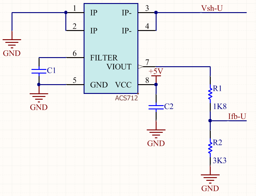
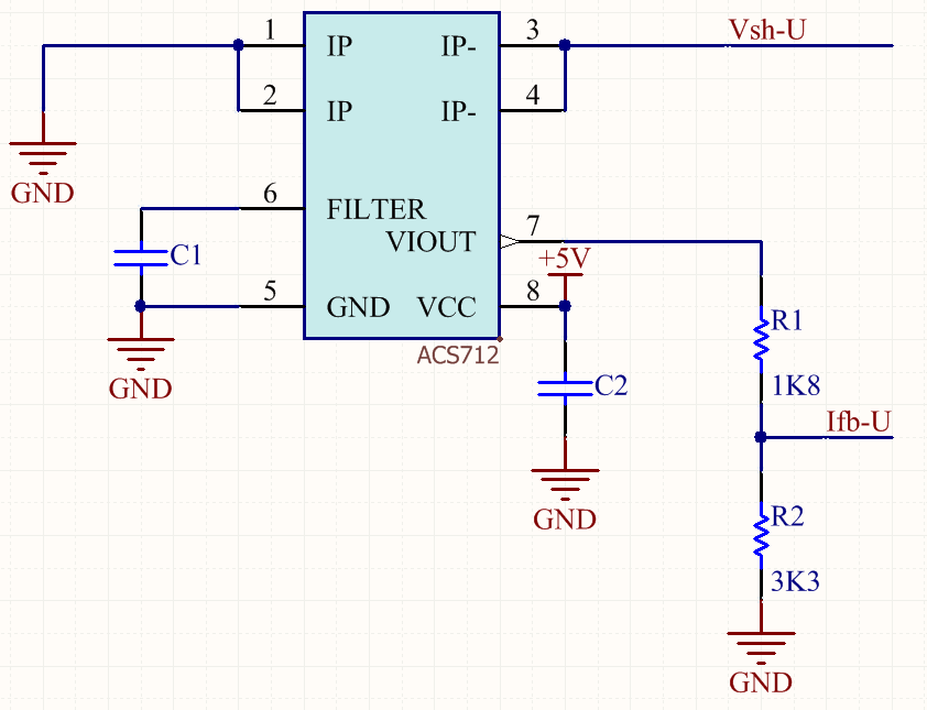
    The circuit that I use to convert 5V to 3.3V is a simple voltage divider with 1K8 and 3K3 resistors

    Thanks in advance

    Andrés
  • Thanks. With a 1.8kohm and 3.3kohm resistor divider you get a bit higher than 50. To calculate it we would have this:

    3.3V * (3.3k+1.8k) / 3.3k = 5.1V

    with 100mV/A of sensor sensitivity this would be 51A, so the define should be

    #define USER_ADC_FULL_SCALE_CURRENT_A (51.0)

    Also what is the polarity of the signal comming back from the sensor? In other words, does the output voltage from the sensor increase as the current into the motor increases? or does the voltage increase as the current coming back from the motor increases?

    And do you have three sensors, one per each phase or only 2? If only two, please confirm you are measuring A and B phases and not C, and that you have configured the number of current sensors as 2 if you have 2 sensors:

    Thanks,

    -Jorge

  • I use 3 sensors, and I configured the number of current sensors
    Yes, I measured the polarity. The current injected in the (-) input makes that the Vout decreased, so my (+) input is connected to GND.
    In other words, when the current that sinks into the sensor increases, its output voltage decreases.
  • Is it possible to take a look at the schematics showing these sensors? I got a bit confused with your statement: "so my (+) input is connected to GND". Also, what currents do you see on the scope? Is it possible to compare the currents from the sensor vs. the current measured with a current probe?
    -Jorge
  • Hi Jorge,

    the schematic

    Notes:

    #define USER_MOTOR_RES_EST_CURRENT      (0.5)

    #define USER_PWM_FREQ_kHz                (10.0)

    #define USER_IQ_FULL_SCALE_CURRENT_A         (27.0)

    #define USER_ADC_FULL_SCALE_CURRENT_A       (51.0)

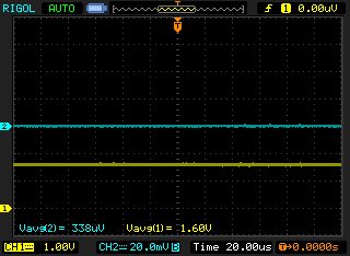
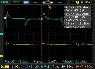
    CH1 is the Ifb-U (voltage probe)

    Ch2 is the U-phase (current probe with sensibility: 50mV / A )

    Without current:

    In the Rs identification:

  • Looking at the sensor datasheet, the specify a minimum output resistance load of 4.7kohm, and you have 5.1kohm. I would recomment the following:

    1. Move the sensor to the motor phase, instead of a direct replacement of a shunt resistor. I think these sensors are not design for PWM switching due to its limited bandwidth (80kHz only). They are design to be in series with the motor winding. So I would short the low side mosfet to ground and place these sensors in series with the motor phases.

    2. Have an output voltage follower, and have the resistor divider on the output of the voltage follower, to have more current source/sink capability and avoid overdriving the output of the sensor

    -Jorge

  • Tu respuesta me lleva a plantear la misma duda inicial. La corriente que sensa el shunt del circuito original NO es la misma que la que va a cada fase del motor(*). Si colocara el sensor en serie con cada fase del motor al tener una lectura de corriente diferente el software no debería funcionar bien.

    (*) Cuando el transistor High conduce, el shunt en serie con el source del transistor Low no sensa esta corriente (que efectivamente circula por la fase del motor), solo se sensa la corriente saliente si se trata de la corriente inducida por la inductancia del motor en el diodo de rueda libre del transistor Low o la corriente entrante de conducción del transistor Low.

    Your answer returns me to the original question. In the original circuit the current sensed by the shunt is not the TOTAL current of each motor phase.It only senses the sinking current when the low transistor is ON and the freewheeling diode sourcing current when the transistor is OFF. Having stated that I imagine that the SAME software cannot behave correctly with different currents.

    Andrés

  • Creo que ya entendi la duda. Cuando el transistor de arriba conduce, tienes razon, en ese instante el shunt no sensa esa corriente, pero la corriente por el shunt no se sensa en ese instante, se sensa cuando el low se prende. Es decir, durante el mismo ciclo de PWM, pero no cuando el de arriba esta prendido, sino cuando el de abajo esta prendido.

    Si se asume ese metodo de sensado de corrient, entonces la corriente que se sensa con un shunt es la misma corriente que se sensa con un sensor en serie con la fase del motor, siempre y cuando se sense mientras el transistor low este encendido.

    Creo que el ruido que muestra la salida del sensor sigue siendo por las dos razones: la corriente de salida del sensor no da para el divisor de resistencia que tienes, y tambien el ancho de banda del sensor no es suficiente pare sensar un PWM.

    Saludos!

    -Jorge

  • Haciendo un análisis general de mi problema lo que veo es que, tanto en el reconocimiento de R como de L, los valores son errados supongo que debido a errores en el sensado de V e I.
    Observando en un osciloscopio esas señales presentan pulsos muy marcados a la frecuencia del PWM (en mi caso 10kHz) lo que es esperable y sucede tanto en el HVkit como en mi implementación. Entiendo que el software que lee los valores en los A/D filtra esos pulsos de alguna manera para obtener los "valores medios" (que son sinusoidales) para usarlos en el cálculo. En esa condición parece deseable que el sensor no tenga un gran ancho de banda de modo de minimizar los pulsos. En todo caso sería de gran utilidad saber como se muestrean las señales y como se calculan los valores como ayuda para encontrar el problema.

    A general view of my problem clearly indicates the calculated values of R and L are wrong due to problems sensing V and I. Measuring with a scope the PWM pulses are clearly visible in both V and I waveshapes in the HVkit as long as in my implementation. I understand that the software reads the A/D converters and finds the mean (sinusoidal) values to calculate L and R. In that situation a larger sensor BW seems to be a problem instead of an advantage. In any case knowing how the sampling and calculations are made would be a great help to solve the problem

    Saludos

    Andrés
  • Las señales se muestrean en el puro medio del PWM, que es donde el low side esta encendido. Como las señales de PWM estan alineadas por un contador que sube y baja, muestreando las señales en el puro medio resulta en un muestreo de el valor medio en cada periodo de PWM. Esto es un tanto estandarizado para circuitos de inversores, ya que de otra manera, por ejemplo, muestreando señales multples veces por periodo resultaria en un ADC mas costoso, que normalmente la aplicacion no lo justifica.
    Por que no hacemos una prueba? Por ejemplo, el lab 3a, lo primero que se hace es se inyecta una señal de corriente DC para recalcular la resistencia de estator. Me puedes mandar la corriente en phase A del osciloscopio cuando se esta inyectando esta corriente de DC? Debe ser la misma especificada en este valor de user.h: USER_MOTOR_RES_EST_CURRENT
    -Jorge
  • Hola Jorge,

    En el post de más arriba están las imágenes. Ésta corriente es la del CH2 sensada durante la identificación de Rs pero en el lab2b, que entiendo que es lo mismo.

    Llamativamente la salida del sensor hall marca 1.63V (tuvo un aumento del 30mV) traducido en corriente es de alrededor de 0.4A (muy cercano al valor que tendría que inyectar), en cambio la punta de corriente en la salida, marca alrededor de 43mV, traducido en corriente es 0.86A.
    No entiendo de donde sale esta diferencia.

    Luego el proceso de identificación da EST_ErrorCode_FluxError

    Saludos
    Andrés
  • Hola Andrés,

    Vamos a probar un numero redondo. Por ejemplo, cambia por favor tu corriente de Rs a 1 A.

    #define USER_MOTOR_RES_EST_CURRENT      (1.0)
    #define USER_MOTOR_MAX_CURRENT          (3.0)

    Y tambien vamos probando usando el kit de desarrollo de alto voltage, para ver que Rs estima. Si no tienes uno de estos kits, entonces mide con un multimetro de fase a fase del motor (totalmente desconectado de la tarjeta), y dividelo entre 2, para saber cual es la resistencia de estator que nos debe de dar una vez injectada la corriente.

    Tambien vamor verificando la punta de corriente. Puedes hacer esto usando una fuente de voltage con una resistencia y probar que la punta de corriente este bien calibrada?

    Saludos,

    -Jorge

  • Jorge,

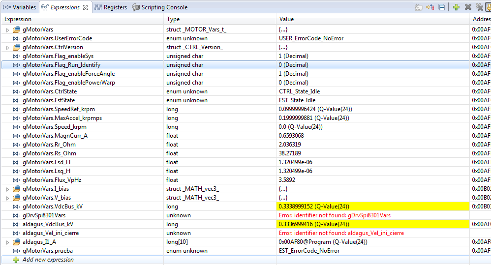
    My own board:

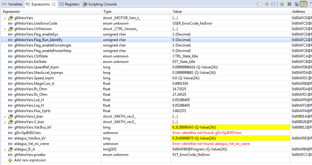
    The HVKit:


    Ocurre una cosa extraña. En mi placa el EST_State_Ls no tarda NADA de tiempo, en cambio en el HVKit durante el mismo estado, tarda varios segundos como se especifica en el 6.5.7 del SPRUHJ1F. Por qué ocurre esto? Alguna idea?

    Gracias

    Andrés

  • Puede ser que mientras hace la identification de Ls ocurre una sobrecorriente. Pero en este punto me concentraria en tener bien la placa con la configuracion de user.h. Puedo ver que los divisores de voltage no son exactamente iguales, por la variable Vbus del HVkit comparado con tu placa. Es posible que mandes todo tu esquematico? Si te sientes incomodo haciendo esto, mandame tu correo electronico y por ahi nos podemos comunicar.

    Saludos,

    -Jorge

  • Jorge,

    los divisores de tensión parecen estar bien, ya que mido con un multimetro la tensión en el puente de diodos y es casi la misma (diferencia de alrededor de 1%) que puedo observar en el debbuger. La tensión de DCBUS es diferente debido a que la tensión de entrada de mi equipo por comodidad es regulable mediante un VariAC  y no siempre pongo exactamente el mismo valor.

    No tengo problema en enviarte los esquemáticos, cabe aclarar que además del capacitor C4 (entre el DCBUS y tierra) que se ve en el pdf hay también en paralelo un capacitor electrolítico de 470uF 450V.

    Saludos

    Andréssensores.pdf 

  • Jorge,

    finalmente logré hacer la identificación del motor correctamente!!! Obtengo los mismos valores que obtuve con el HVKit.

    El problema era que yo compré un modulo ya armado para Arduino y éste venía con un capacitor que me estaba seteando el ancho de banda a 8kHz (en la imagen es el C1).

    Al cambiar ese capacitor por uno de 1nF (de acuerdo con la hoja de datos) se solucionó el problema!!

    Gracias por tu ayuda en este aspecto.

    Igualmente me gustaría entender por qué con el método de las resistencias+amplificador no puedo hacer la identificación correctamente. El esquemático de esto se ve observa en el pdf del post anterior

    Saludos

    Andrés