This thread has been locked.

If you have a related question, please click the "Ask a related question" button in the top right corner. The newly created question will be automatically linked to this question.

Effective voltage of motor under rated power

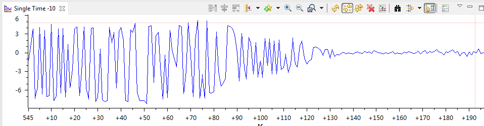
When I test my ACIM  motor by using lab13e, the motor working at maximum speed ,and I Increasing load , normally the phase voltage will reached 15V which is the effective value of rated voltage .The Vector sum of α current and β current close to 1(PU) , but the phase voltage still can not reached 15V. Let's see the pictures.

  • Stefan,

    I've forwarded this over to Dave Wilson to see if he can comment

    is it possible this is an issue with the modulation being sinewave and not over-modulation of space vector or trapezoidal?

  • Hi Stefan,

    Thanks for your inquiry.

    I assume the values shown in German are the rated values of the motor, taken from the data sheet?  For example, rated current is 90.7 amps and rated voltage is 15 volts?

    Also, is the graph you included a graph of voltage?  If so, is it alpha or beta voltage, or phase voltage?

    If this is supposed to be a symmetrical AC waveform, the first thing I notice (after the fact that it does not look sinusoidal at all) is the incredible negative offset associated with the waveforms, which seems to go away after the waveform amplitude dies out.  I can't understand this.

    Also, I see that the current vector amplitude is close to unity PU, which would suggest that it is at its maximum value.  If the current regulation is working correctly, this could explain why the voltage does not reach 15 volts, since the current regulators will only apply enough voltage to achieve the reference current values for Id and Iq.

    Perhaps you could provide a little bit more clarity on my questions above in order for me to get a better understanding of what is going on.


    Thanks and Best Regards,

    Dave


  • Dave,

    1.

    The data sheet of the motor is upload, please check it .

    The graph is phase voltage, and the graph produced by CCS compiler and the collection frequency is very low ,so it does not look sinusoidal at all . But we still can notice the Max phase  voltage not reached 15V .

    " Why the waveform amplitude dies out "

    Sorry , I didn't describe clearly ,  the waveform amplitude dies out ,because I set the velocity to 0 . 

    And My motor power can not reach the maximum , maybe the reason is the  Max phase  voltage not reached 15V.

    2.

    By the way , when speed more than 1540rpm ,  I cut the Id setting , so the motor work in weak magnetic state , when speed over 1540rpm,  Id(over 1540rpm) = Id(less than 1540rpm) * ( 1540/speed  ).  The motor can not reach max speed until I use this strategy .

    The strategy is not the reason why Max phase voltage can not reached 15V , TI provided Field-Weakening plan , but I have no data about it .

    3.

    When I test my ACIM  motor by using lab13e, when load overrate , the motor will shaking , how can I add a protective measures, the Torque from FAST is not quite right, I can not use it.

    (ABM)Anh_E21041_3.pdf

  • Chris,

    The voltage of alpha and beta is Per-unit value  , what is their bases ?  USER_IQ_FULL_SCALE_VOLTAGE_V ?

    Is all of voltage with PU value based on USER_IQ_FULL_SCALE_VOLTAGE_V  ?

  • Dave,
    I did an experiment today , The input voltage source of the controller is 24V, and I increased to 30V ,  the max of phase voltage reached to 12V. (Please ignore the sinusoidal wave problem)

     Obviously , the motor run a better performance, because the voltage vector is greater , correct ? 

    So,  my motor can not reach the rated power, I  suspect it is a issue of too low phase voltage , but I not sure where the problem is.

  • Hi Stefan,

    Thanks for the additional information.

    First, I agree that there is a problem with our torque calculation for AC Induction Machines which seems to be restricted to high current applications.  I believe it is caused by saturation as a result of fixed-point math.  I have been told that this problem has been resolved with our new floating-point version of InstaSPIN.

    In a field oriented system, the voltage is generated by the two PI current controllers.  So if the voltage is too low, it has to be one of two reasons:

    1.  The PI current regulators are supplying the commanded current for each axis.  The regulators will not produce any more voltage than what is required to support the commanded currents.  So in this case, the FOC system is operating like it should be.

    2.  The PI current regulators are NOT supplying the commanded current for each axis.  In most cases, it is because, the system has saturated.  Usually the q-axis current regulator saturates first.  This is because the d-axis current regulator gets first dibs on the available voltage, and the q-axis regulator gets what is left over.  So when you see the low voltage problem, please tell me the value of the following variables:

    USER_IQ_FULL_SCALE_VOLTAGE_V =

    maxVsMag_pu =

    Idq_in.value[0] =

    Idq_in.value[1] =

    Idq_ref.value[0] =

    Idq_ref.value[1] =

    Vdq_out.value[0] =

    Vdq_out.value[1] =

    Thanks,

    Dave


  • Dave,

    Today I tested another ACIM motor. The situation is still not good. Here is the value of  the variables in different condition.There are 2 files , motor datasheet and value of  the variables . 

    Anh_E18124_engl.pdf

    variables.c
    USER_IQ_FULL_SCALE_VOLTAGE_V =  (24.0) 
    
    maxVsMag_pu =   pUserParams->maxVsMag_pu = USER_MAX_VS_MAG_PU = 1 ;
    
    //********************************************
    Speed = 4.12krpm; Load = 0 N��m ;
    
    Idq_in.value[0] = 0.1345422864
    
    
    Idq_in.value[1] = 0.1229215264
    
    
    Idq_ref.value[0] =0
    
    
    Idq_ref.value[1] =0.16498667
    
    
    Vdq_out.value[0] =0.148935318
    
    
    Vdq_out.value[1] =0.651847899
    
    //********************************************
    Speed = 2.06krpm; Load = 0 N��m ;
    
    Idq_in.value[0] = 0.1347380877
    
    
    Idq_in.value[1] = 0.1442247629
    
    
    Idq_ref.value[0] =0
    
    
    Idq_ref.value[1] =0.1121465564
    
    
    Vdq_out.value[0] =0.06969686022
    
    
    Vdq_out.value[1] =0.3277651072
    
    //********************************************
    Speed = 2.06krpm; Load = 2.22 N��m ��
    
    Idq_in.value[0] = 0.3559394479
    
    
    Idq_in.value[1] = 0.3589113951
    
    
    Idq_ref.value[0] =0
    
    
    Idq_ref.value[1] =0.3497021198
    
    
    Vdq_out.value[0] =0.1223757863
    
    
    Vdq_out.value[1] =0.8174455762
    
    //********************************************
    Speed = 4.12 krpm; Load = 0.555 N��m ��
    
    Idq_in.value[0] = 0.2114536762
    
    
    Idq_in.value[1] = 0.1800981164
    
    
    Idq_ref.value[0] =0
    
    
    Idq_ref.value[1] =0.1778497696
    
    
    Vdq_out.value[0] =0.118756175
    
    
    Vdq_out.value[1] =0.862888813


  • Hi Stefan,Thanks for the data you sent me.
    From looking at the variables.c file, it looks like you have set your Id reference current to zero. Could you please confirm whether this is the case? ACIM motors need a non-zero value of Id to operate properly.
    Thanks,Dave
  • Hi Dave,

    Thanks for your reply ,

         No, I set the Id reference current to 50% of the maximum current of the motor.  I uploaded the user.h file, and parameters of motor E18124.

        I've met a new problem these days. My motor can not start with load, and there will be jitter phenomenon. I try to reduce the acceleration and the speed reference, but useless.  But the motor can carry the load at the time of the operation, although the load capacity is not big. 

       I use lab13e to test my motor . With the same routine, It can be a good control of the motor E20363.

    E18124.pdf

    77114.user.h

    E20363.pdf