This thread has been locked.

If you have a related question, please click the "Ask a related question" button in the top right corner. The newly created question will be automatically linked to this question.

Changing trip zone 3*TBCLK duration for latch to a longer time.

Other Parts Discussed in Thread: CONTROLSUITE, MOTORWARE

Hi,

I am working on a custom board based on the boostxldrv8301_revB. I have set up the GPIO 17 as TZ3 and am triggering a one shot trip from that pin for short circuit protection. This works fine in the lab.

In the manual it says that the condition needs to be longer than three times the TBCLK low pulses for it to latch on. However I am working on the system which may have noise induced in it, so I was wondering if there is a way to increase this time from 3*TBCLK to some higher value so that I don't get wrong trips?

The chip that I am using pulls the pin low for almost 7ms, and I can increase it to 50 ms if needed, so missing a real trip event is not a problem but I certainly do not want any  spurious trip events because of noise.

Thanks for help.

  • Hi Nikhil,

    You are correct on the 3 TBCLK cycle min spec.  

    You will notice that this same section of the user's guide states: " The asynchronous trip makes sure that if clocks are missing for any reason, the outputs can still be tripped by a valid event present on TZn inputs ".  This is referring to the setting of the GPIO Qualification to be Asynchronous.  

    TI example software in ControlSUITE configures the TZ pins for ASYNC qualification to support that the shortest events, but you can add delay by changing the GPIO qualification setting.  

    Jeff

  • Hi Jeff,

    Sorry for the late reply. I was busy with something else here. 

    Anyway I was thinking that in my project I have three different situations which I want the trip protection on. I have a short functions which detects under/over voltage, I have I2t function and then I have the short circuit protection. Of these only the short circuit uses external circuit to trigger the trip zone. So instead of writing separate codes for all three I was thinking I could define a single error variable and in a small if loop force the TZFRC register to trip the PWMs. So in real situations by  checking the error variable we would know why it tripped as well. Here is my code but it is not working:

    1. I changed the GPIO 17 from TZ3 to GPIO again.

    2. In proj_lab20.c code I have:

    void short_ckt (void)
    {
      gShort = HAL_readGpio(halHandle, GPIO_Number_17); // ON - OFF switch
      if (gShort ==0)
      {
        gShortCount++;
        if (gShortCount > 6)
        {
         gJedlError=1;
        }
       }
    }

    I call this function in the forever loop. I have similar functions for other protections with error values of 2, 3 and 4.

    In the forever loop I have this

    if (gJedlError > 0)
    {
      PWM_setOneShotTrip(pwmHandle);
    }

    I was hoping that this would set the trip register since I thought that the other registers would already be set. But apperantly this code does not work. Do you have any suggestions or ideas of how I can force the trip from the code?

  • I am using the Motorware lab 20 as my basis for the program.
    Also how can I add delay in the GPIO Asynchronous setting if I need to? I could not find anything related to that.
  • Nikhil,

    Not sure how you define "delay".

    You could switch the GPIO qualification from async to sync on the SYSCLK, then you can define a time window where the signal must remain active for the trip to occur. This would provide delay equal to the time window you define. Not sure if this is what you asking for.

    Jeff
  • Hi Jeff,

    That's exactly what I meant by delay. I want to be able to change the time during which the trigger needs to be active before the trip occurs.

    But I don't know how to do that. Is there an example of this somewhere?

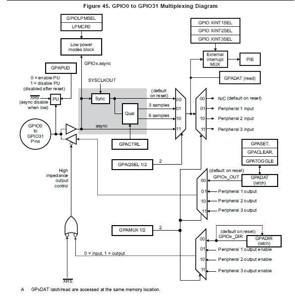
  • Nikhil, GPIO Qualification is discussed in the System and Control User's Guide.  From your Tags it looks like you are using the 027, so check out the TMS320F2802x/TMS320F2802xx Piccolo System Control and Interrupts Reference Guide document, see section 4.4 and figure 49.  

    Also refer to figure 45 for an overview of how the GPIO multiplexing works.  Note how the input qualification is before the the connection to the peripheral functional for the selected GPIO pin function. 

    Jeff

  • Thanks Jeff that helped me a lot.