This thread has been locked.

If you have a related question, please click the "Ask a related question" button in the top right corner. The newly created question will be automatically linked to this question.

Add SPI read in Lab12b on th HV Kit with F28069

Other Parts Discussed in Thread: MOTORWARE, DRV8301, ISO7241A, CONTROLSUITE

Dear My Friends:

I have a PMSM , resolver kit and Hv-kit with F28069 controller  and I hope to use SPI(slave) to get PMSM postion from resolver Kit(master).I found that there is a SPI-A interface in H2 connector in pin1,3,5 and 7 in the Hv-Kit.I am trying to add SPI(slave) firmware in F28069 of Hv-kit to read rotation postion of PMSM from TI-resolver Kit.Is it possible to implement the function of reading resolver data by SPI ?

Best Regards,

Sheng-Hua

  • Hi Sheng-Hua,

    Yes, you can add SPI-A to your MotorWare project.  The function HAL_setupSpiA() is already available in hal.c, in which it calls functions from SPI.c.    Use this function very much like HAL_setupSpiB() is already used, adding it to HAL_setParams().  

    You will also need to configure the GPIO to be for SPI mode.  This is what I am using for the 06x:

    // SPI-SIMO
    GPIO_setMode(obj->gpioHandle,GPIO_Number_16,GPIO_16_Mode_SPISIMOA);
    GPIO_setPullup(obj->gpioHandle,GPIO_Number_16, GPIO_Pullup_Enable);

    // SPI-SOMI
    GPIO_setMode(obj->gpioHandle,GPIO_Number_17,GPIO_17_Mode_SPISOMIA);
    GPIO_setPullup(obj->gpioHandle,GPIO_Number_17, GPIO_Pullup_Enable);

    // SPI-CLK
    GPIO_setMode(obj->gpioHandle,GPIO_Number_18,GPIO_18_Mode_SPICLKA);
    GPIO_setPullup(obj->gpioHandle,GPIO_Number_18, GPIO_Pullup_Enable);

    // SPI-STE
    GPIO_setMode(obj->gpioHandle,GPIO_Number_19,GPIO_19_Mode_SPISTEA_NOT);
    GPIO_setPullup(obj->gpioHandle,GPIO_Number_19, GPIO_Pullup_Enable);

    Here's the function I am using for SPI-A in slave mode. 

    void HAL_setupSpiA(HAL_Handle handle)
    {
    HAL_Obj *obj = (HAL_Obj *)handle;

    SPI_reset(obj->spiAHandle);
    SPI_setClkPolarity(obj->spiAHandle,SPI_ClkPolarity_OutputRisingEdge_InputFallingEdge);
    SPI_disableLoopBack(obj->spiAHandle);
    SPI_setCharLength(obj->spiAHandle,SPI_CharLength_16_Bits);

    SPI_setMode(obj->spiAHandle,SPI_Mode_Slave);

    SPI_setClkPhase(obj->spiAHandle,SPI_ClkPhase_Normal);
    SPI_enableTx(obj->spiAHandle);

    SPI_enableChannels(obj->spiAHandle);
    SPI_enableTxFifoEnh(obj->spiAHandle);
    SPI_enableTxFifo(obj->spiAHandle);
    SPI_setTxDelay(obj->spiAHandle,0);
    SPI_clearTxFifoInt(obj->spiAHandle);
    SPI_enableRxFifo(obj->spiAHandle);

    //not needed for slave mode SPI_setBaudRate(obj->spiAHandle,(SPI_BaudRate_e)(0x0003));
    SPI_setSuspend(obj->spiAHandle,SPI_TxSuspend_free);
    SPI_enable(obj->spiAHandle);

    return;
    } // end of HAL_setupSpiA() function

    Don't forget to initialize the SPI-A object in HAL_init():

    // initialize the SPIA handle
    obj->spiAHandle = SPI_init((void *)SPIA_BASE_ADDR,sizeof(SPI_Obj));

    and enable the clock to SPI-A with  CLK_enableSpiaClock(obj->clkHandle) in the functionHAL_setupPeripheralClks().

    Hopefully this helps,

    Jeff


    Did a reply answer your question? If yes, please click the "Verify Answer" button located at the bottom of that post.

    C2000 TI Wiki Pages
    TI Forum Sitemap

    ControlSUITE
    Motor Drive & Control (everything)

    CLA FAQs
    Workshop Material!

    InstaSPIN Wiki
    InstaSPIN
    FAST Software Encoder

    InstaSPIN-FOC
    InstaSPIN-MOTION
    InstaSPIN-BLDC

    InstaSPIN-FOC/MOTION User's Guide
    MotorWare 
    InstaSPIN Training

  • Dear Jeff:

    Thanks your help. I will add the above code into my LAB12b project and test SPI funciton.

    Best Regards,

    Sheng-Hua

  • Dear Jeff:


    Thanks your hint.

    There is an another issue for SPI read from resolver kit between Drv8301+F28069 and Hv-Kit+F28069.

    I had implemented SPI read code in LAB12b from resolver kit in Drv8301+F28069 and got correct resover data before.Now I am trying to add the code in Hv-Kit+F28069 and found it can't work. (No any interrupt happen for SPI read event)

    It is so intersting. What is different between Hv-Kit and Drv-8301 in Firmware and Hard setting? I found that there is a file of Drv8310.c in Drv-8301 kit.


    Best Regards,

    Sheng-Hua

    ~~~~~~~~~~~~~~~~~~~~~~~~~~~~~~~~~~~~~~~~~~~~~~~~~~~~~~~~~~~~~~~~~~~~~~~~~~~~~~~~~~~~~~~~~~


    Below is my program code of Lab12b  and some relavent include files in control suit is in the attached file.


    ///////////////////////////////////////////////////////////////////////////////////////////////////////////

    #ifdef FLASH

    #pragma CODE_SECTION(mainISR,"ramfuncs");

    #endif


    // Include header files used in the main function


    // **************************************************************************

    // the defines


    #define LED_BLINK_FREQ_Hz   5


    // **************************************************************************

    // the globals


    uint_least16_t gCounter_updateGlobals = 0;


    bool Flag_Latch_softwareUpdate = true;


    CTRL_Handle ctrlHandle;


    HAL_Handle halHandle;


    USER_Params gUserParams;


    HAL_PwmData_t gPwmData = {_IQ(0.0), _IQ(0.0), _IQ(0.0)};


    HAL_AdcData_t gAdcData;


    _iq gMaxCurrentSlope = _IQ(0.0);


    #ifdef FAST_ROM_V1p6

    CTRL_Obj *controller_obj;

    #else

    CTRL_Obj ctrl;                              //v1p7 format

    #endif


    ENC_Handle encHandle;

    ENC_Obj enc;


    SLIP_Handle slipHandle;

    SLIP_Obj slip;


    ST_Obj st_obj;

    ST_Handle stHandle;


    uint16_t gLEDcnt = 0;


    volatile MOTOR_Vars_t gMotorVars = MOTOR_Vars_INIT;


    #ifdef FLASH

    // Used for running BackGround in flash, and ISR in RAM

    extern uint16_t *RamfuncsLoadStart, *RamfuncsLoadEnd, *RamfuncsRunStart;

    #endif


    #ifdef DRV8301_SPI

    // Watch window interface to the 8301 SPI

    DRV_SPI_8301_Vars_t gDrvSpi8301Vars;

    #endif


    _iq gFlux_pu_to_Wb_sf;

    _iq gFlux_pu_to_VpHz_sf;

    _iq gTorque_Ls_Id_Iq_pu_to_Nm_sf;

    _iq gTorque_Flux_Iq_pu_to_Nm_sf;


    // **************************************************************************

    // the functions


    // ====================================================================

    // Initialize SPI in slave mode to receive position data from resolver

    // ====================================================================

    void spi_fifo_init()

    {

    // Initialize SPI FIFO registers

       SpiaRegs.SPICCR.bit.SPISWRESET=0; // Reset SPI


       //SpiaRegs.SPICCR.all=0x001F;       //16-bit character, Loopback mode

       SpiaRegs.SPICCR.all=0x000F;       //16-bit character


       //SpiaRegs.SPICTL.all=0x0017;       //Interrupt enabled, Master/Slave XMIT enabled


       SpiaRegs.SPICTL.all=0x0013;          //Interrupt enabled, Slave enabled


       SpiaRegs.SPISTS.all=0x0000;


       /*

         v->SPICTL.bit.TALK         = 1;     // enable talk

       v->SPICTL.bit.SPIINTENA     = 0;     // SPI int disable

              v->SPIBRR = 9;                       // Baud rate


       */


       // 2015.0618 by ysh .......

       // SpiaRegs.SPIBRR=0x0063;           // Baud rate

       SpiaRegs.SPICTL.bit.TALK         = 1;     // enable talk

       SpiaRegs.SPIBRR=0x0009;           // Baud rate

       ///////////////////////////////////////////////////////////


       SpiaRegs.SPIFFTX.all=0xC022;     // Enable FIFO's, set TX FIFO level to 4

       SpiaRegs.SPIFFRX.all=0x0022;     // Set RX FIFO level to 4

       SpiaRegs.SPIFFCT.all=0x00;

       SpiaRegs.SPIPRI.all=0x0010;


       SpiaRegs.SPICCR.bit.SPISWRESET=1; // Enable SPI


       SpiaRegs.SPIFFTX.bit.TXFIFO=1;

       SpiaRegs.SPIFFRX.bit.RXFIFORESET=1;

    }


    ////////////////////////////////////////////////////

    void InitSpiA_Gpio()

    {


       EALLOW;

    /* Enable internal pull-up for the selected pins */

    // Pull-ups can be enabled or disabled by the user.

    // This will enable the pullups for the specified pins.

    // Comment out other unwanted lines.


    // GpioCtrlRegs.GPAPUD.bit.GPIO3 = 0;   // Enable pull-up on GPIO3 (SPISOMIA)

    // GpioCtrlRegs.GPAPUD.bit.GPIO5 = 0;   // Enable pull-up on GPIO5 (SPISIMOA)


       GpioCtrlRegs.GPAPUD.bit.GPIO16 = 0;   // Enable pull-up on GPIO16 (SPISIMOA)

       GpioCtrlRegs.GPAPUD.bit.GPIO17 = 0;   // Enable pull-up on GPIO17 (SPISOMIA)

       GpioCtrlRegs.GPAPUD.bit.GPIO18 = 0;   // Enable pull-up on GPIO18 (SPICLKA)

       GpioCtrlRegs.GPAPUD.bit.GPIO19 = 0;   // Enable pull-up on GPIO19 (SPISTEA)


    // GpioCtrlRegs.GPBPUD.bit.GPIO54 = 0;   // Enable pull-up on GPIO54 (SPISIMOA)

    // GpioCtrlRegs.GPBPUD.bit.GPIO55 = 0;   // Enable pull-up on GPIO55 (SPISOMIA)

    // GpioCtrlRegs.GPBPUD.bit.GPIO56 = 0;   // Enable pull-up on GPIO56 (SPICLKA)

    // GpioCtrlRegs.GPBPUD.bit.GPIO57 = 0;   // Enable pull-up on GPIO57 (SPISTEA)


    /* Set qualification for selected pins to asynch only */

    // This will select asynch (no qualification) for the selected pins.

    // Comment out other unwanted lines.


    //      GpioCtrlRegs.GPAQSEL1.bit.GPIO3 = 3; // Asynch input GPIO3 (SPISOMIA)

    //      GpioCtrlRegs.GPAQSEL1.bit.GPIO5 = 3; // Asynch input GPIO5 (SPISIMOA)


       GpioCtrlRegs.GPAQSEL2.bit.GPIO16 = 3; // Asynch input GPIO16 (SPISIMOA)

       GpioCtrlRegs.GPAQSEL2.bit.GPIO17 = 3; // Asynch input GPIO17 (SPISOMIA)

       GpioCtrlRegs.GPAQSEL2.bit.GPIO18 = 3; // Asynch input GPIO18 (SPICLKA)

       GpioCtrlRegs.GPAQSEL2.bit.GPIO19 = 3; // Asynch input GPIO19 (SPISTEA)


    // GpioCtrlRegs.GPBQSEL2.bit.GPIO54 = 3; // Asynch input GPIO54 (SPISIMOA)

    // GpioCtrlRegs.GPBQSEL2.bit.GPIO55 = 3; // Asynch input GPIO55 (SPISOMIA)

    // GpioCtrlRegs.GPBQSEL2.bit.GPIO56 = 3; // Asynch input GPIO56 (SPICLKA)

    // GpioCtrlRegs.GPBQSEL2.bit.GPIO57 = 3; // Asynch input GPIO57 (SPISTEA)


    /* Configure SPI-A pins using GPIO regs*/

    // This specifies which of the possible GPIO pins will be SPI functional pins.

    // Comment out other unwanted lines.


    // GpioCtrlRegs.GPAMUX1.bit.GPIO3 = 2; // Configure GPIO3 as SPISOMIA

    // GpioCtrlRegs.GPAMUX1.bit.GPIO5 = 2; // Configure GPIO5 as SPISIMOA


       GpioCtrlRegs.GPAMUX2.bit.GPIO16 = 1; // Configure GPIO16 as SPISIMOA

       GpioCtrlRegs.GPAMUX2.bit.GPIO17 = 1; // Configure GPIO17 as SPISOMIA

       GpioCtrlRegs.GPAMUX2.bit.GPIO18 = 1; // Configure GPIO18 as SPICLKA

       GpioCtrlRegs.GPAMUX2.bit.GPIO19 = 1; // Configure GPIO19 as SPISTEA


    // GpioCtrlRegs.GPBMUX2.bit.GPIO54 = 1; // Configure GPIO54 as SPISIMOA

    // GpioCtrlRegs.GPBMUX2.bit.GPIO55 = 1; // Configure GPIO55 as SPISOMIA

    // GpioCtrlRegs.GPBMUX2.bit.GPIO56 = 1; // Configure GPIO56 as SPICLKA

    // GpioCtrlRegs.GPBMUX2.bit.GPIO57 = 1; // Configure GPIO57 as SPISTEA


       EDIS;

    }


    void main(void)

    {

    uint_least8_t estNumber = 0;


    #ifdef FAST_ROM_V1p6

    uint_least8_t ctrlNumber = 0;

    #endif


    // Only used if running from FLASH

    // Note that the variable FLASH is defined by the project

    #ifdef FLASH

    // Copy time critical code and Flash setup code to RAM

    // The RamfuncsLoadStart, RamfuncsLoadEnd, and RamfuncsRunStart

    // symbols are created by the linker. Refer to the linker files.

    memCopy((uint16_t *)&RamfuncsLoadStart,(uint16_t *)&RamfuncsLoadEnd,(uint16_t *)&RamfuncsRunStart);

    #endif


    // initialize the hardware abstraction layer

    halHandle = HAL_init(&hal,sizeof(hal));


    // check for errors in user parameters

    USER_checkForErrors(&gUserParams);


    // store user parameter error in global variable

    gMotorVars.UserErrorCode = USER_getErrorCode(&gUserParams);


    // do not allow code execution if there is a user parameter error

    if(gMotorVars.UserErrorCode != USER_ErrorCode_NoError)

       {

         for(;;)

           {

             gMotorVars.Flag_enableSys = false;

           }

       }


    // initialize the user parameters

    USER_setParams(&gUserParams);


    // set the hardware abstraction layer parameters

    HAL_setParams(halHandle,&gUserParams);


    // initialize the controller

    #ifdef FAST_ROM_V1p6

    ctrlHandle = CTRL_initCtrl(ctrlNumber, estNumber);               //v1p6 format (06xF and 06xM devices)

    controller_obj = (CTRL_Obj *)ctrlHandle;

    #else

    ctrlHandle = CTRL_initCtrl(estNumber,&ctrl,sizeof(ctrl));  //v1p7 format default

    #endif


    {

       CTRL_Version version;


       // get the version number

       CTRL_getVersion(ctrlHandle,&version);


       gMotorVars.CtrlVersion = version;

    }


    // set the default controller parameters

    CTRL_setParams(ctrlHandle,&gUserParams);


    // setup faults

    HAL_setupFaults(halHandle);


    // initialize the interrupt vector table

    HAL_initIntVectorTable(halHandle);


    // enable the ADC interrupts

    HAL_enableAdcInts(halHandle);


    // enable global interrupts

    HAL_enableGlobalInts(halHandle);


    // enable debug interrupts

    HAL_enableDebugInt(halHandle);


    // disable the PWM

    HAL_disablePwm(halHandle);


    // initialize the ENC module

    encHandle = ENC_init(&enc, sizeof(enc));


    // setup the ENC module

    ENC_setup(encHandle, 1, USER_MOTOR_NUM_POLE_PAIRS, USER_MOTOR_ENCODER_LINES, 0, USER_IQ_FULL_SCALE_FREQ_Hz, USER_ISR_FREQ_Hz, 8000.0);


    // initialize the SLIP module

    slipHandle = SLIP_init(&slip, sizeof(slip));


    // setup the SLIP module

    SLIP_setup(slipHandle, _IQ(gUserParams.ctrlPeriod_sec));


    // initialize the SpinTAC Components

    stHandle = ST_init(&st_obj, sizeof(st_obj));


    // setup the SpinTAC Components

    ST_setupVelCtl(stHandle);

    ST_setupPosConv(stHandle);


    #ifdef DRV8301_SPI

    // turn on the DRV8301 if present

    HAL_enableDrv(halHandle);

    // initialize the DRV8301 interface

    HAL_setupDrvSpi(halHandle,&gDrvSpi8301Vars);

    #endif


    // enable DC bus compensation

    CTRL_setFlag_enableDcBusComp(ctrlHandle, true);


    // compute scaling factors for flux and torque calculations

    gFlux_pu_to_Wb_sf = USER_computeFlux_pu_to_Wb_sf();

    gFlux_pu_to_VpHz_sf = USER_computeFlux_pu_to_VpHz_sf();

    gTorque_Ls_Id_Iq_pu_to_Nm_sf = USER_computeTorque_Ls_Id_Iq_pu_to_Nm_sf();

    gTorque_Flux_Iq_pu_to_Nm_sf = USER_computeTorque_Flux_Iq_pu_to_Nm_sf();


    /////////////////////////////////////////////////////////////////

    // 2015.0526 by ysh for resolver data .....st .....

       Uint16 i;


    // Step 1. Initialize System Control:

    // PLL, WatchDog, enable Peripheral Clocks

    // This example function is found in the F2806x_SysCtrl.c file.


       //InitSysCtrl();


    // Step 2. Initalize GPIO:

    // This example function is found in the F2806x_Gpio.c file and

    // illustrates how to set the GPIO to it's default state.

    // InitGpio(); // Skipped for this example

    // Setup only the GP I/O only for SPI-A functionality

       //InitSpiaGpio();

       InitSpiA_Gpio();


    // Step 3. Initialize PIE vector table:

    // Disable and clear all CPU interrupts


       //DINT;

       //IER = 0x0000;

       //IFR = 0x0000;


    // Initialize PIE control registers to their default state:

    // This function is found in the F2806x_PieCtrl.c file.


       //InitPieCtrl();


    // Initialize the PIE vector table with pointers to the shell Interrupt

    // Service Routines (ISR).

    // This will populate the entire table, even if the interrupt

    // is not used in this example. This is useful for debug purposes.

    // The shell ISR routines are found in F2806x_DefaultIsr.c.

    // This function is found in F2806x_PieVect.c.


       //InitPieVectTable();


    // Interrupts that are used in this example are re-mapped to

    // ISR functions found within this file.

       EALLOW; // This is needed to write to EALLOW protected registers


       PieVectTable.SPIRXINTA = &spiRxFifoIsr;


       //PieVectTable.SPITXINTA = &spiTxFifoIsr;

       EDIS;   // This is needed to disable write to EALLOW protected registers


    // Step 4. Initialize all the Device Peripherals:

    // This function is found in F2806x_InitPeripherals.c

    // InitPeripherals(); // Not required for this example

       spi_fifo_init();   // Initialize the SPI only


    // Step 5. User specific code, enable interrupts:


    // Initalize the send data buffer

     for(i=0; i<2; i++)

       {

           sdata[i] = i;

       }

       rdata_point = 0;


    // Enable interrupts required for this example

       PieCtrlRegs.PIECTRL.bit.ENPIE = 1;   // Enable the PIE block


       PieCtrlRegs.PIEIER6.bit.INTx1=1;     // Enable PIE Group 6, INT 1

       //PieCtrlRegs.PIEIER6.bit.INTx1=1;     // Enable PIE Group 6, INT 1


       // 2015.0618 by ysh .....disable spi tx mode

       //PieCtrlRegs.PIEIER6.bit.INTx2=1;     // Enable PIE Group 6, INT 2

       //IER=0x20;                          // Enable CPU INT6

       IER= IER | 0x20;                                                      // Enable CPU INT6

       EINT;                               // Enable Global Interrupts


    //////////////////////////////////////////////////////////////


    for(;;)

    {

       // Waiting for enable system flag to be set


              ~~~~~~~~~~~~~~~~~~~~~~~~~~~~~~

              ~~~~~~~~~~~~~~~~~~~~~~~~~~~~~~

              ~~~~~~~~~~~~~~~~~~~~~~~~~~~~~~

       } //end of for loop


    } //end of main() program


    __interrupt void spiRxFifoIsr(void)

    {

       Uint16 i;

       for(i=0;i<2;i++)

       {

           //rdata[i]=SpiaRegs.SPIRXBUF;     // Read data

                 rvl_data[i]=SpiaRegs.SPIRXBUF;     // Read data

       }


       rvl_ang= rvl_data[0]/4095*360;

       rvl_ang_temp[1]= rvl_ang_temp[0];               // previous relsolver angle

       rvl_ang_temp[0]=rvl_ang;                                  // current resolver angle

       /*

       for(i=0;i<2;i++)                   // Check received data

       {

           if(rdata[i] != rdata_point+i) error();

       }

    */

       rdata_point++;

       SpiaRegs.SPIFFRX.bit.RXFFOVFCLR=1; // Clear Overflow flag

       SpiaRegs.SPIFFRX.bit.RXFFINTCLR=1; // Clear Interrupt flag

       PieCtrlRegs.PIEACK.all|=0x20;       // Issue PIE ack

    }


    interrupt void mainISR(void)

    {

    static uint16_t stCnt = 0;

    CTRL_Obj *obj = (CTRL_Obj *)ctrlHandle;


    // toggle status LED

    if(gLEDcnt++ > (uint_least32_t)(USER_ISR_FREQ_Hz / LED_BLINK_FREQ_Hz))

    {

       HAL_toggleLed(halHandle,(GPIO_Number_e)HAL_Gpio_LED2);

       gLEDcnt = 0;

    }


    // compute the electrical angle

    //ENC_calcElecAngle(encHandle, HAL_getQepPosnCounts(halHandle));


    // .... it is ok ....

    test_ang= (rvl_ang) /360*2;

    ///////////////////////////////////


    ~~~~~~~~~~~~~~~~~~~~~~~~

    ~~~~~~~~~~~~~~~~~~~~~~~~

    ~~~~~~~~~~~~~~~~~~~~~~~~~

    } // end of mainISR loop

    ////////////////////////////////////////////////////

  • Dear Jeff:

    After importing Lab12b project in F28069 at Hv-kit ,I can't find the function of HAL_setupSpiA in hal.c.
    However It can be found in Lab12b project at Drv-8301. There are a little different in hal.c between Hv-kit and Drv-8301. It is so intersting . Can I still use the HAL_setupSpiA in Hv-Kit?

    Best Regards,
    Sheng-Hua
  • Hi ShengHua,

    Keep in mind that there are different hal files for the different target boards.

    For the 06x and DRV8301 kit:
    C:\TI\motorware\motorware_1_01_00_15\sw\modules\hal\boards\drv8301kit_revD\f28x\f2806x\src

    For the 06x and HV kit:
    C:\TI\motorware\motorware_1_01_00_15\sw\modules\hal\boards\hvkit_rev1p1\f28x\f2806x\src

    Be sure to make the changes to both sets of files if you want SPI-A support for both target boards.

    Jeff
  • Dear Jeff:

    I have used motorware with 06x and Hv-Kit in the directory of "C:\TI\motorware\motorware_1_01_00_14\sw\modules\hal\boards\hvkit_rev1p1\f28x\f2806x\src".

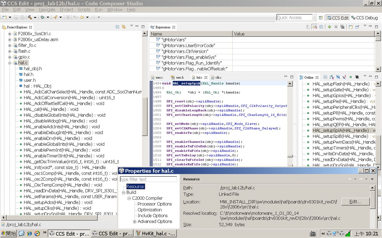
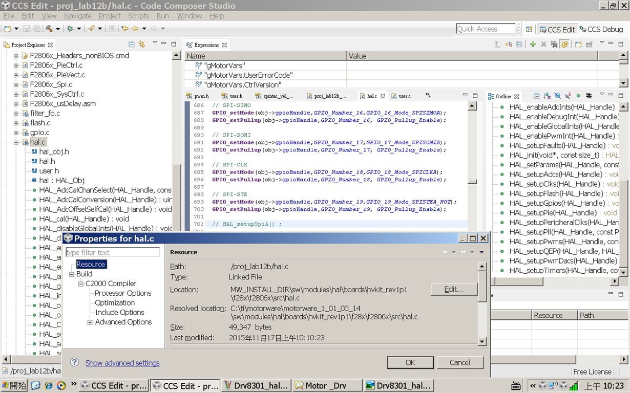
    I can't find hal_setupSpiA() in the hal.c on the Hv-kit but I can only find it in the hal.c on the Drv-8301 Kit. (Please reference the following figure files)

    What differnt is there between Hv_kit and Drv8301 in hal.c?  How can I add SPIA interface in Hv-kit+F28069 to communicate with resolver kit?

    hal.c in Drv8301-kit

    hal.c in Hv-kit


    Best Regrds,

    Sheng-Hua


  • Dear Jeff:

    I have used motorware with 06x and Hv-Kit in the directory of "C:\TI\motorware\motorware_1_01_00_14\sw\modules\hal\boards\hvkit_rev1p1\f28x\f2806x\src". I can't find hal_setupSpiA() in the hal.c on the Hv-kit but I can only find it in the hal.c on the Drv-8301 Kit.

    What differnt is there between Hv_kit and Drv8301 in hal.c?  

    How can I add SPIA interface in Hv-kit+F28069 to communicate with resolver kit?

    Can I use hal.c in the drv-8301 instead of hal.c in the Hv-kit ?

    Best Regards,

    Sheng-Hua

  • Hi Sheng-Hua,

    Just to confirm I understand your system correctly, please confirm or correct the following descriptions of your project:

    1. You have one motor in your project (PMSM with resolver)
    2. You are running InstaSPIN on the 28069 HV kit to run the motor
    3. You are using the TI resolver kit with an SPI interface to read the motor position
    4. You want to read motor position from reolver kit with HV kit via SPI
    5. You are adding SPI-A software to InstaSPIN on the 28069 HV kit

    Based on the above being correct, let me answer your most recent questions:

    • What differnt is there between Hv_kit and Drv8301 in hal.c?  
      • Each board has a different hal.c since the hal.c reflects the boards layout and functionality of the application.
      • There will be differences in pin connections, which peripherals are being used and how those peripherals are configured.
    • How can I add SPIA interface in Hv-kit+F28069 to communicate with resolver kit?
      • You can add hal_setupSpiA() to the hal.c for the HV-kit
    • Can I use hal.c in the drv-8301 instead of hal.c in the Hv-kit ?
      • I suggest making the required changes to the hal.c already in the HV kit directory.  
      • A good way to start is to compare the difference between the files using a file comparison SW like BeyondCompare
      • Then move over the SPI-A related code from the 8301 hal.c 

    When you have this working, how are you going to use the resolver information with your InstaSPIN code?  Maybe measure the accuracy of the angle estimation by the FAST observer?  

    Good luck with your project.

    Jeff

  • Dear Jeff:

    Thanks your help. Below is the architecture of the project as you describe.

    1. We have one motor in your project (PMSM with resolver)
    2. We are running InstaSPIN on the 28069 HV kit to run the motor
    3. We are using the TI resolver kit with an SPI interface to read the motor position
    4. We want to read motor position from reolver kit with HV kit via SPI
    5. We are adding SPI-A software to InstaSPIN on the 28069 HV kit
    6. Add torque sensor and use ADC to meaure torque
    7. use torque control to control the torque force.

    We hope to add step 6 and step 7 to control torque in next stage and there will be two issues which need be solved.

    As for ADC measure in step 6, we found the ADC channels(A0-A7,B0-B7) are occupied in Hv-Kit and how can setup ADC channel for torque sensor.

    In this project ,we will use the resolver information to control torque force.

    Could we directly use the angle estimation by FAST Estimation to control torque force instead of the angle from resolver?

    Is there a SPI sample code for Hv-Kit in F28069?

    Best Regards,

    Sheng-Hua

  • Dear Jeff:

    Thanks your help.

    Below is the SPIA code of "F28069+Drv-8301" for you reference.The SPIA fucntion can work with Ti-Reslover Kit in "F28069+Drv-8301",but it can't work in "Hv-Kit+F28069". I don't know why it can't work at "Hv-Kit+F28069".

    I found there are some difference between Drv-8301 and Hv-Kit.

    In Drv-8301, there a U5(ISO7241A) device for SPI bewteen F28069 and Resover kit(F28035) and I can't find it on Hv-kit.

    Is it necessary element for SPI transmition?

    ~~~~~~~~~~~~~~~~~~~~~~~~~~~~~~~~~~~~~~~~~~~~~~~~~~~~~~~~~~~~~~~~~~~

    // ====================================================================

    // Initialize SPI in slave mode to receive position data from resolver

    // ====================================================================

    // ..........modify from control suit @ F8069 v141 .......

    void spi_fifo_init()

    {

    // Initialize SPI FIFO registers

      SpiaRegs.SPICCR.bit.SPISWRESET=0; // Reset SPI

      //SpiaRegs.SPICCR.all=0x001F;       //16-bit character, Loopback mode

      SpiaRegs.SPICCR.all=0x000F;       //16-bit character

      //SpiaRegs.SPICTL.all=0x0017;       //Interrupt enabled, Master/Slave XMIT enabled

      SpiaRegs.SPICTL.all=0x0013;          //Interrupt enabled, Slave enabled

      SpiaRegs.SPISTS.all=0x0000;

      /*

        v->SPICTL.bit.TALK         = 1;     // enable talk

      v->SPICTL.bit.SPIINTENA     = 0;     // SPI int disable

             v->SPIBRR = 9;                       // Baud rate

      */

      // 2015.0618 by ysh .......

      // SpiaRegs.SPIBRR=0x0063;           // Baud rate

      SpiaRegs.SPICTL.bit.TALK         = 1;     // enable talk

      SpiaRegs.SPIBRR=0x0009;           // Baud rate

      ///////////////////////////////////////////////////////////

      SpiaRegs.SPIFFTX.all=0xC022;     // Enable FIFO's, set TX FIFO level to 4

      SpiaRegs.SPIFFRX.all=0x0022;     // Set RX FIFO level to 4

      SpiaRegs.SPIFFCT.all=0x00;

      SpiaRegs.SPIPRI.all=0x0010;

      SpiaRegs.SPICCR.bit.SPISWRESET=1; // Enable SPI

      SpiaRegs.SPIFFTX.bit.TXFIFO=1;

      SpiaRegs.SPIFFRX.bit.RXFIFORESET=1;

    }

    ////////////////////////////////////////////////////

    void InitSpiA_Gpio()

    {

      EALLOW;

    /* Enable internal pull-up for the selected pins */

    // Pull-ups can be enabled or disabled by the user.

    // This will enable the pullups for the specified pins.

    // Comment out other unwanted lines.

    // GpioCtrlRegs.GPAPUD.bit.GPIO3 = 0;   // Enable pull-up on GPIO3 (SPISOMIA)

    // GpioCtrlRegs.GPAPUD.bit.GPIO5 = 0;   // Enable pull-up on GPIO5 (SPISIMOA)

      GpioCtrlRegs.GPAPUD.bit.GPIO16 = 0;   // Enable pull-up on GPIO16 (SPISIMOA)

      GpioCtrlRegs.GPAPUD.bit.GPIO17 = 0;   // Enable pull-up on GPIO17 (SPISOMIA)

      GpioCtrlRegs.GPAPUD.bit.GPIO18 = 0;   // Enable pull-up on GPIO18 (SPICLKA)

      GpioCtrlRegs.GPAPUD.bit.GPIO19 = 0;   // Enable pull-up on GPIO19 (SPISTEA)

    // GpioCtrlRegs.GPBPUD.bit.GPIO54 = 0;   // Enable pull-up on GPIO54 (SPISIMOA)

    // GpioCtrlRegs.GPBPUD.bit.GPIO55 = 0;   // Enable pull-up on GPIO55 (SPISOMIA)

    // GpioCtrlRegs.GPBPUD.bit.GPIO56 = 0;   // Enable pull-up on GPIO56 (SPICLKA)

    // GpioCtrlRegs.GPBPUD.bit.GPIO57 = 0;   // Enable pull-up on GPIO57 (SPISTEA)

    /* Set qualification for selected pins to asynch only */

    // This will select asynch (no qualification) for the selected pins.

    // Comment out other unwanted lines.

    //      GpioCtrlRegs.GPAQSEL1.bit.GPIO3 = 3; // Asynch input GPIO3 (SPISOMIA)

    //      GpioCtrlRegs.GPAQSEL1.bit.GPIO5 = 3; // Asynch input GPIO5 (SPISIMOA)

      GpioCtrlRegs.GPAQSEL2.bit.GPIO16 = 3; // Asynch input GPIO16 (SPISIMOA)

      GpioCtrlRegs.GPAQSEL2.bit.GPIO17 = 3; // Asynch input GPIO17 (SPISOMIA)

      GpioCtrlRegs.GPAQSEL2.bit.GPIO18 = 3; // Asynch input GPIO18 (SPICLKA)

      GpioCtrlRegs.GPAQSEL2.bit.GPIO19 = 3; // Asynch input GPIO19 (SPISTEA)

    // GpioCtrlRegs.GPBQSEL2.bit.GPIO54 = 3; // Asynch input GPIO54 (SPISIMOA)

    // GpioCtrlRegs.GPBQSEL2.bit.GPIO55 = 3; // Asynch input GPIO55 (SPISOMIA)

    // GpioCtrlRegs.GPBQSEL2.bit.GPIO56 = 3; // Asynch input GPIO56 (SPICLKA)

    // GpioCtrlRegs.GPBQSEL2.bit.GPIO57 = 3; // Asynch input GPIO57 (SPISTEA)

    /* Configure SPI-A pins using GPIO regs*/

    // This specifies which of the possible GPIO pins will be SPI functional pins.

    // Comment out other unwanted lines.

    // GpioCtrlRegs.GPAMUX1.bit.GPIO3 = 2; // Configure GPIO3 as SPISOMIA

    // GpioCtrlRegs.GPAMUX1.bit.GPIO5 = 2; // Configure GPIO5 as SPISIMOA

      GpioCtrlRegs.GPAMUX2.bit.GPIO16 = 1; // Configure GPIO16 as SPISIMOA

      GpioCtrlRegs.GPAMUX2.bit.GPIO17 = 1; // Configure GPIO17 as SPISOMIA

      GpioCtrlRegs.GPAMUX2.bit.GPIO18 = 1; // Configure GPIO18 as SPICLKA

      GpioCtrlRegs.GPAMUX2.bit.GPIO19 = 1; // Configure GPIO19 as SPISTEA

    // GpioCtrlRegs.GPBMUX2.bit.GPIO54 = 1; // Configure GPIO54 as SPISIMOA

    // GpioCtrlRegs.GPBMUX2.bit.GPIO55 = 1; // Configure GPIO55 as SPISOMIA

    // GpioCtrlRegs.GPBMUX2.bit.GPIO56 = 1; // Configure GPIO56 as SPICLKA

    // GpioCtrlRegs.GPBMUX2.bit.GPIO57 = 1; // Configure GPIO57 as SPISTEA

      EDIS;

    }

    ~~~~~~~~~~~~~~~~~~~~~~~~~~~~~~~~~~~~~~~~~~~~~~~~~~~~~~~~~~~~~~~~~

    main()

    {

    ~~~~~~~~~~~~~~~~~~~~~~~~~~~~

       InitSpiA_Gpio();

      EALLOW; // This is needed to write to EALLOW protected registers

       PieVectTable.SPIRXINTA = &spiRxFifoIsr;

      EDIS;   // This is needed to disable write to EALLOW protected registers

       spi_fifo_init();   // Initialize the SPI only

     // Enable interrupts required for this example

      PieCtrlRegs.PIECTRL.bit.ENPIE = 1;   // Enable the PIE block

      PieCtrlRegs.PIEIER6.bit.INTx1=1;     // Enable PIE Group 6, INT 1

      // 2015.0618 by ysh .....disable spi tx mode

      //PieCtrlRegs.PIEIER6.bit.INTx2=1;     // Enable PIE Group 6, INT 2

      //IER=0x20;                          // Enable CPU INT6

      IER= IER | 0x20;                                                      // Enable CPU INT6

      EINT;                               // Enable Global Interrupts

    for(;;){

    ~~~~~~~~~~~~~~~~~~~~~~~~

    }

    // mainisr

    ~~~~~~~~~~~~~~~~~

    } //end of main

    __interrupt void spiRxFifoIsr(void)

    {

      Uint16 i;

       for(i=0;i<2;i++)

      {

          //rdata[i]=SpiaRegs.SPIRXBUF;     // Read data

                rvl_data[i]=SpiaRegs.SPIRXBUF;     // Read data

      }

      rvl_ang= rvl_data[0]/4095*360;

      rvl_ang_temp[1]= rvl_ang_temp[0];               // previous relsolver angle

      rvl_ang_temp[0]=rvl_ang;                                  // current resolver angle

      rdata_point++;

      SpiaRegs.SPIFFRX.bit.RXFFOVFCLR=1; // Clear Overflow flag

      SpiaRegs.SPIFFRX.bit.RXFFINTCLR=1; // Clear Interrupt flag

      PieCtrlRegs.PIEACK.all|=0x20;       // Issue PIE ack

    }

    ~~~~~~~~~~~~~~~~~~~~~~~~~~~~~~~~~~~~~~~~~~~~~~~~~~~~~~~~~~~~~~~~~~~~~~~~~~~~~

    Best Regards,

    Sheng-Hua

  • Hi Sheng-Hua,

    The ISO7241A is an optical isolation unit provided on the DRV8301.  You will need to pay close attention to your ground loops and the high voltage with the HV kit connected to the resolver kit.  

    Could we directly use the angle estimation by FAST Estimation to control torque force instead of the angle from resolver?

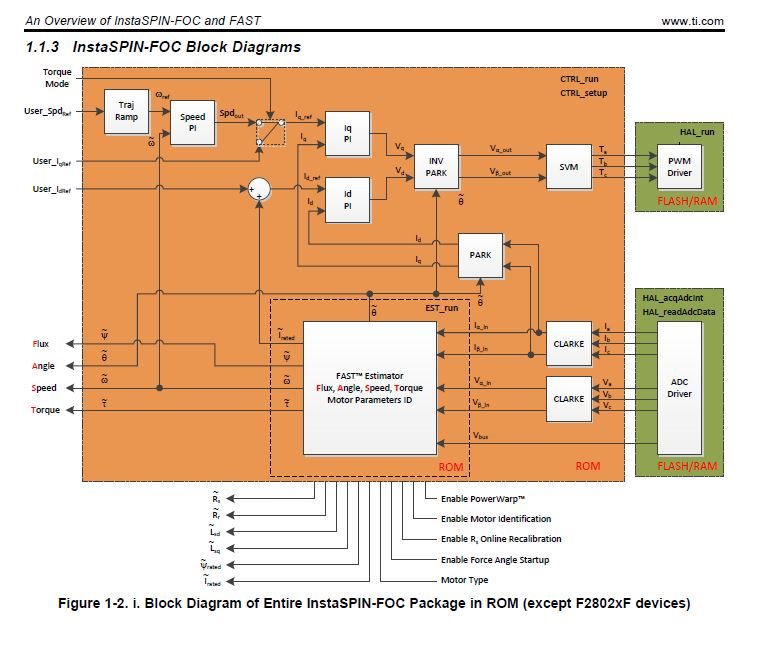
    For many applications yes.  InstaSPIN's FAST observer was specifically designed to enable sensorless FOC (no HALL sensor, encoder or resolver).  But there are limitations.  Please see chapter 1 in the InstaSPIN User's Guide.  Also note that lab05A is an example of using InstaSPIN in torque mode.

    Is there a SPI sample code for Hv-Kit in F28069?

    Sorry, there I am not aware of any example SPI code for the HV-kit from either MotorWare or ControlSUITE.  We are working to close these gaps.  The example I provided for SPI on DRV8301 is good reference to port it to the HV kit.

    Jeff

    Did a reply answer your question? If yes, please click the "Verify Answer" button located at the bottom of that post.

    C2000 TI Wiki Pages
    TI Forum Sitemap

    ControlSUITE
    Motor Drive & Control (everything)

    CLA FAQs
    Workshop Material!

    InstaSPIN Wiki
    InstaSPIN
    FAST Software Encoder

    InstaSPIN-FOC
    InstaSPIN-MOTION
    InstaSPIN-BLDC

    InstaSPIN-FOC/MOTION User's Guide
    MotorWare 
    InstaSPIN Training

  • Dear Jeff:

    Thanks your help.

    I try to modify the file "Example_2806xSpi_FFDLB_int.c" in the directory of "C:\ti\controlSUITE\device_support\f2806x\v141\F2806x_examples_ccsv5\spi_loopback_interrupts" of control suit to test SPI function in the "Hv-kit+F28069" with resolver kit.It seems to get the correct rotate position of PMSM from resolver kit.Below is the modified file to SPI reading in "F28069+Hv-Kit" (slave) for Resolver kit(master).

    //###########################################################################
    //
    //!  \addtogroup f2806x_example_list
    //!  <h1>SPI Digital Loop Back with Interrupts(spi_loopback_interrupts)</h1>
    //!
    //!  This program uses the internal loop back test mode of the peripheral.
    //!  Other then boot mode pin configuration, no other hardware configuration
    //!  is required. Both interrupts and the SPI FIFOs are used.
    //!
    //!  A stream of data is sent and then compared to the received stream.
    //!  The sent data looks like this: \n
    //!  0000 0001 \n
    //!  0001 0002 \n
    //!  0002 0003 \n
    //!  .... \n
    //!  FFFE FFFF \n
    //!  FFFF 0000 \n
    //!  etc.. \n
    //!  This pattern is repeated forever.
    //!
    //!  \b Watch \b Variables \n
    //!  - \b sdata , Data to send
    //!  - \b rdata , Received data
    //!  - \b rdata_point , Used to keep track of the last position in
    //!    the receive stream for error checking
    //
    //###########################################################################
    // $TI Release: F2806x C/C++ Header Files and Peripheral Examples V141 $
    // $Release Date: January 19, 2015 $
    // $Copyright: Copyright (C) 2011-2015 Texas Instruments Incorporated -
    //             http://www.ti.com/ ALL RIGHTS RESERVED $
    //###########################################################################

    #include "DSP28x_Project.h"     // Device Headerfile and Examples Include File

    // Prototype statements for functions found within this file.
    __interrupt void spiTxFifoIsr(void);
    __interrupt void spiRxFifoIsr(void);
    void delay_loop(void);
    void spi_fifo_init(void);
    void error();

    Uint16 sdata[2];     // Send data buffer
    Uint16 rdata[2];     // Receive data buffer
    Uint16 rdata_point;  // Keep track of where we are
                         // in the data stream to check received data

    void main(void)
    {
       Uint16 i;

    // Step 1. Initialize System Control:
    // PLL, WatchDog, enable Peripheral Clocks
    // This example function is found in the F2806x_SysCtrl.c file.
       InitSysCtrl();

    // Step 2. Initalize GPIO:
    // This example function is found in the F2806x_Gpio.c file and
    // illustrates how to set the GPIO to it's default state.
    // InitGpio();  // Skipped for this example
    // Setup only the GP I/O only for SPI-A functionality
       InitSpiaGpio();

    // Step 3. Initialize PIE vector table:
    // Disable and clear all CPU interrupts
       DINT;
       IER = 0x0000;
       IFR = 0x0000;

    // Initialize PIE control registers to their default state:
    // This function is found in the F2806x_PieCtrl.c file.
       InitPieCtrl();

    // Initialize the PIE vector table with pointers to the shell Interrupt
    // Service Routines (ISR).
    // This will populate the entire table, even if the interrupt
    // is not used in this example.  This is useful for debug purposes.
    // The shell ISR routines are found in F2806x_DefaultIsr.c.
    // This function is found in F2806x_PieVect.c.
       InitPieVectTable();

    // Interrupts that are used in this example are re-mapped to
    // ISR functions found within this file.
       EALLOW;  // This is needed to write to EALLOW protected registers
       PieVectTable.SPIRXINTA = &spiRxFifoIsr;
       PieVectTable.SPITXINTA = &spiTxFifoIsr;
       EDIS;   // This is needed to disable write to EALLOW protected registers

    // Step 4. Initialize all the Device Peripherals:
    // This function is found in F2806x_InitPeripherals.c
    // InitPeripherals(); // Not required for this example
       spi_fifo_init();   // Initialize the SPI only

    // Step 5. User specific code, enable interrupts:

    // Initalize the send data buffer
       for(i=0; i<2; i++)
       {
          sdata[i] = i;
       }
       rdata_point = 0;

    // Enable interrupts required for this example
       PieCtrlRegs.PIECTRL.bit.ENPIE = 1;   // Enable the PIE block
       PieCtrlRegs.PIEIER6.bit.INTx1=1;     // Enable PIE Group 6, INT 1
       PieCtrlRegs.PIEIER6.bit.INTx2=1;     // Enable PIE Group 6, INT 2
       IER=0x20;                            // Enable CPU INT6
       EINT;                                // Enable Global Interrupts

    // Step 6. IDLE loop. Just sit and loop forever (optional):
        for(;;);

    }

    // Some Useful local functions
    void delay_loop()
    {
        long      i;
        for (i = 0; i < 1000000; i++) {}
    }

    void error(void)
    {
       __asm("     ESTOP0");  //Test failed!! Stop!
        for (;;);
    }

    void spi_fifo_init()
    {
    // Initialize SPI FIFO registers
       SpiaRegs.SPICCR.bit.SPISWRESET=0; // Reset SPI

       SpiaRegs.SPICCR.all=0x001F;       //16-bit character, Loopback mode
       SpiaRegs.SPICTL.all=0x0017;       //Interrupt enabled, Master/Slave XMIT enabled
       SpiaRegs.SPISTS.all=0x0000;
       SpiaRegs.SPIBRR=0x0063;           // Baud rate
       SpiaRegs.SPIFFTX.all=0xC022;      // Enable FIFO's, set TX FIFO level to 4
       SpiaRegs.SPIFFRX.all=0x0022;      // Set RX FIFO level to 4
       SpiaRegs.SPIFFCT.all=0x00;
       SpiaRegs.SPIPRI.all=0x0010;

       SpiaRegs.SPICCR.bit.SPISWRESET=1;  // Enable SPI

       SpiaRegs.SPIFFTX.bit.TXFIFO=1;
       SpiaRegs.SPIFFRX.bit.RXFIFORESET=1;
    }

    __interrupt void spiTxFifoIsr(void)
    {
        Uint16 i;
        for(i=0;i<2;i++)
        {
           SpiaRegs.SPITXBUF=sdata[i];      // Send data
        }

        for(i=0;i<2;i++)                    // Increment data for next cycle
        {
           sdata[i] = sdata[i] + 1;
        }

        SpiaRegs.SPIFFTX.bit.TXFFINTCLR=1;  // Clear Interrupt flag
        PieCtrlRegs.PIEACK.all|=0x20;       // Issue PIE ACK
    }

    __interrupt void spiRxFifoIsr(void)
    {
        Uint16 i;
        for(i=0;i<2;i++)
        {
            rdata[i]=SpiaRegs.SPIRXBUF;     // Read data
        }
        for(i=0;i<2;i++)                    // Check received data
        {
            if(rdata[i] != rdata_point+i) error();
        }
        rdata_point++;
        SpiaRegs.SPIFFRX.bit.RXFFOVFCLR=1;  // Clear Overflow flag
        SpiaRegs.SPIFFRX.bit.RXFFINTCLR=1;  // Clear Interrupt flag
        PieCtrlRegs.PIEACK.all|=0x20;       // Issue PIE ack
    }

    //===========================================================================
    // No more.
    //===========================================================================

  • Hi Sheng-Hua,

    I have done same thing before. I have connected motorware (HV-kit) and resolver to digital conversion kit and then pumped angle to the motorware through SPI connection. Same as in your case, I made resolver to digital conversion kit as the master SPI and the motorware as the slave SPI terminal. But I used lab5a to do that. Anyway what I did was, 

    First I changed hal.c and configured gpio pins to SPI,

    // SPI-SIMO
    GPIO_setMode(obj->gpioHandle,GPIO_Number_16,GPIO_16_Mode_SPISIMOA);

    // SPI-SOMI
    GPIO_setMode(obj->gpioHandle,GPIO_Number_17,GPIO_17_Mode_SPISOMIA);

    // SPI-CLK
    GPIO_setMode(obj->gpioHandle,GPIO_Number_18,GPIO_18_Mode_SPICLKA);

    // SPI-STE
    GPIO_setMode(obj->gpioHandle,GPIO_Number_19,GPIO_19_Mode_SPISTEA_NOT);

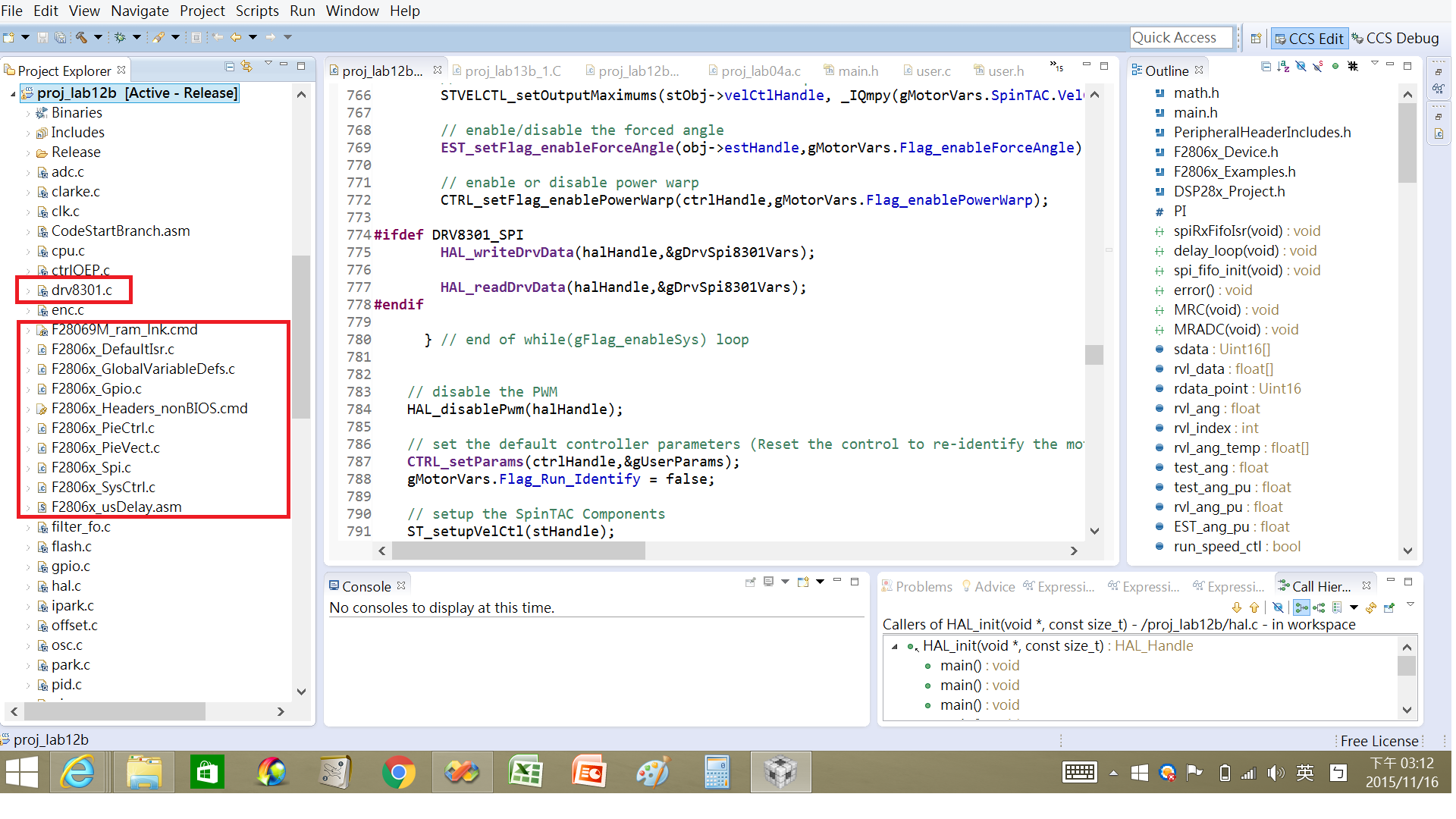
    I added 6 filres externally from control suit to the project as in the image. 


    Then called InitSysCtrl(); function above the Spi_config(); function which is mentioned below.

    Then configured SPI in a function and put motorware side in to slave SPI mode. Call this function just above the forever for loop.

    void Spi_config(void){

    SpiaRegs.SPICCR.all = 0x0000;
    SpiaRegs.SPICCR.all =0x000F; // Reset on, rising edge, 16-bit char bits


    // SpiaRegs.SPICTL.all =0x0006; // Enable master mode, normal phase,
    // enable talk, and SPI int disabled.

    SpiaRegs.SPICTL.all =0x0000;
    SpiaRegs.SPICTL.all =0x0002;
    SpibRegs.SPIBRR =0x007F;

    }

    Then captured angle data in mainISR funtion

    Spi_angle_data = SpiaRegs.SPIRXBUF;
    Spi_electrical_angle = Spi_angle_data << 8;  // convert to iq format

    Those are the only changes I have made to work SPI and SPI worked with this. I did not used SPI interrupt for the communication. But it worked smoothly.

    Hope this will be helpful to you.

    Thanks.


  • Dear Lakshan :

    Thank you very much and I will try later.
    May you have a nice day.

    Best Regards,
    Sheng-Hua
  • I have the same problem with you now,have you solved it yet?
  • Dear FoCus:

    We have solved it and we can use the resolver data to control PMSM at specific speed.

    Best Regards,
    sheng-hua
  • 哥们,我刚接触Hvkit,用的也是F28069的control card,现在也要加SPI功能。方便留个QQ或者邮箱吗?有问题我想请教一下,谢谢啦!

  • Dear FoCus:

    My E-mail is "ShengHuaYang@itri.org.tw".

    Best Regards,
    Sheng-Hua