This thread has been locked.

If you have a related question, please click the "Ask a related question" button in the top right corner. The newly created question will be automatically linked to this question.

Regarding Regenerative Braking

Hi Chris and all,

I knew that instaspin operate for 4-quadrant. But I haven't use resister and switching device for over voltage regulation. I have developed my firmware on top of lab5a with external resolver angle feedback. I tried to test regenerative braking in many ways, but still I couldn't test that properly. I have following problems,

1) I always brake the motor after apply zero Iq current command  (Iq_ref = 0). Then I expect a voltage burst on DC bus. But i couldn't see something like that up to now. 

2) I disconnected the battery from the inverter DC bus and rotate motor shaft with considerable rpm. Iq_ref was set to zer0 (iq_ref = 0).I was expecting to build large voltage on dc bus. I could see some voltage on that time (around 15V), but I think that was not sufficient with applied rpm to rotor shaft. 

3) Should I make any changes to firmware for good regenerative performances.

4) Guide me with the necessary steps for testing of regenerative braking. 

Thank you.

  • Nice, I'm also curious for regenerative Braking.

    If I may guess : you need to make a torque controller with a negative IQ.The current needs to flow from the motor.

    If it work direct out of the box? I doubt that, so I don't think it will be easy.


  • correct, try commanding negative IqRef_A
  • Hi Lakshan,

    What motor are you running? I suppose that it's PMSM.

    1. If the motor run without field weakening, you can disable the speed close loop, and set the Iq_ref to oppiste value to do the regenerative braking. For example, if the motor run clockwise with positive torque current, you need to set a negative Iq_ref without speed close loop.  Likewise, if the motor run anti-clockwise with negative torque current, you need to set a positive  Iq_ref without speed close loop.

    2. If the motor run with field weakening, you can do the same setting as above, and set the Id_ref to zero also.

    Please be careful, the dc_bus will maybe boost very high during regenerative braking, especially motor run with field weakening. You need to pay attention to the voltage is no higher than the permissible voltage value of capacitor in the  long time.

    Best Regards,

    Yanming Luo

  • Let me add some comments with Yanming's answer.

    Please keep in mind that as Yanming mentioned, torque(Iq) and speed should be opposite direction for running in Generating mode(2 & 4 Quadrant) as below figure. The perfect solution for regenerative braking test is a using MG(Motor-Generator) set. If you can use MG rig, the motor shaft will be rotated with external coupled motor or other energy that can rotator the motor shaft. In that case, you can get the braking energy via putting opposite direction torque(Iq) in generator side(motor also can be generator).

    If you don't have any MG rig, the motor load should have a high inertia for regeneration. In other words, your motor system should run for dozens of seconds during free run. You can use both of Torque mode and Speed mode. The speed mode is more easy and safe for testing. Here is a brief test procedure.

    1) Rotate motor up to high enough speed with speed control mode (assumption of positive speed command). 
    2) Set the speed command zero or negative with high acceleration. 

    In that case, Iq reference will go to maximum negative value and motor will still rotate with positive direction. It means that motor will run at the Fourth Quadrant mode and the inertia energy will go back to DC_Cap or Battery thru reverse DC link current.  

    You can also use Torque mode likewise.

  • Tested with negative Iq_ref value with and without DC bus (Batteries) voltage supply.  Without DC bus voltage, for negative iq_ref and positive rpm, a considerably large voltage could be seen with respect zero Iq_ref.  With DC bus supply, for negative iq_ref and positive rpm, a small current flow into the batteries was seen (didn't test with high speed and large negative number).

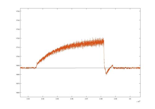
    Applied Iq_ref= 2.5 for positive side, rpm was arount 300 rpm, then applied Iq_ref = -1.5 to brake. DC bus current plot was like below, 

    Is this a good result ? or is this a something like normal current spike in to the battery?

  • If the regeneration energy of your systems is not high, the test result looks like reasonable. When you put the negative torque for braking, how long motor runs until stop?

    What's the meaning of "Without DC bus voltage"? how can you driving a motor without DC bus source? Can you explain your test setup a little more detail?

  • Hello,

    Could you please give a theoretical background to your explanation or atleast are you very sure this works? Because you are nothing but stopping the motor and saying all the energy will get into battery. Will it not go into heating up the resistor?

    And isn't this energy coming from just the magnetic field of the rotor and not kinetic energy of the rotor?

    Thanks,

    Kedar