This thread has been locked.

If you have a related question, please click the "Ask a related question" button in the top right corner. The newly created question will be automatically linked to this question.

PU unit current conversion, current supplied is too small.

Other Parts Discussed in Thread: LAUNCHXL-F28069M, DRV8305

While doing the labs I have noticed the problem that my power supply is only showing 3A of current usage, while I set my USER_IQ_FULL_SCALE_CURRENT_A to 24 and USER_ADC_FULL_SCALE_CURRENT_A to 47.14. If I try to go any higher, I get current too high errors which is obvious. I am using the LAUNCHXL-F28069M board with the DRV8305 Booster. These are my motor parameters:

#define USER_MOTOR_TYPE                 MOTOR_Type_Pm
#define USER_MOTOR_NUM_POLE_PAIRS       (20)
#define USER_MOTOR_Rr                   (NULL)
#define USER_MOTOR_Rs                   (0.0484125465)
#define USER_MOTOR_Ls_d                 (3.53583055e-05)
#define USER_MOTOR_Ls_q                 (3.53583055e-05)
#define USER_MOTOR_RATED_FLUX           (0.0241114106)
#define USER_MOTOR_MAGNETIZING_CURRENT  (NULL)
#define USER_MOTOR_RES_EST_CURRENT      (3.0)
#define USER_MOTOR_IND_EST_CURRENT      (-3.0)
#define USER_MOTOR_MAX_CURRENT          (24.00)
#define USER_MOTOR_FLUX_EST_FREQ_Hz     (20.0) 
#define USER_MOTOR_ENCODER_LINES        (1024.0)
#define USER_MOTOR_MAX_SPEED_KRPM       (1.920)
#define USER_SYSTEM_INERTIA             (0.2552739978)
#define USER_SYSTEM_FRICTION            (0.7534176111)
#define USER_SYSTEM_BANDWIDTH_SCALE		(1.0)

As you can see I've already went and done most of the labs, the motor is correctly Identified, I can do position control with an incremental encoder with lab13a. I would like to start pushing more current through the motor. This is probably a [PU] vs [A] kind of problem, because when I observe IqRef_A during debugging, it actually goes all the way to 23.9999, but the power supply (which is capable of doing 10A@24V) only shows an output of 3A. What I would like to know is how can I start setting values in actual amps and not PU, or at least convert them in a meaningful way, so that I know what I'm doing. How is this all scaled? Any kind of help is much appreciated.

  • 1.
    USER_ADC_FULL_SCALE_CURRENT_A is set by HW scaling, absolutely nothing else. Don't increase this trying to increase current.

    USER_IQ_FULL_SCALE_CURRENT_A is just set to slightly larger than half of USER_ADC_FULL_SCALE_CURRENT_A

    so neither of these values should ever change for your HW

    2. USER_MOTOR_MAX_CURRENT can be set up to half of USER_ADC_FULL_SCALE_CURRENT_A
    and represents the min/max IqRef_A (peak phase current) that can be commanded by the speed controller to the torque controller

    3. Power supply current != Peak motor phase current

    4. you need a load for your motor to actually use more current, you can't just command it

    5. while you are using a different lab, in lab10 look at how we pull out the value for gMotorVars.Is
    this is the peak current being applied


    per unit to amps is discussed in SPRUHJ1 and you can see some of the calculations in the user.h/.c file
  • 1. Yes, I understood that that much by reading the documentation, I was just trying to provide as much information as I could in my initial post.

    2. As above.

    3. So in theory the booster I'm using can provide 20A per phase and 15A RMS per phase?

    4. I am applying a load, while using Lab 13a, because of that load there is a constant position error which does not decrease and I can see that IqRef_A tops out at a Q-value of 24.0 (value of USER_MOTOR_MAX_CURRENT) while the power supply only measures ~2.5-3A being outputted. Even further increasing the steady-state error does not increase the current output. Although the driver and motor should tolerate more. How can I make them output more? that is my goal and question.

    5. I will look into it.


    Thank you for your answers!

  • "IqRef_A tops out at a Q-value of 24.0"
    you are commanding max torque from your controller/driver for the HW design
    if you have a current probe you should see just under 24A peak current if you have a large enough power supply/battery

    power supply current != peak phase current
  • I understand the difference, as I am sending a peak phase current Iq set point for the Iq regulator. My question is, why can't I put out more current? Why can't I ask the driver to push more current through the motor? Because right now I am drawing a maximum of 3A at stall. I would like to be able to push more. The hardware is certainly capable of drawing more.
  • at stall you aren't able to estimate the rotor flux angle so you aren't able to apply full torque, regardless of a maximum IqRef_A command from the speed controller.

    have you tested your control at higher speed to see if you can produce rated torque (lower than stall)?
  • Yes, I did try it at high speeds. I am not able to stop the motor, and when I try then the current actually rises above the mentioned ~3A, but that is with high speeds. Shouldn't FOC allow for full torque at zero speed? I have ported over the overmodulation parts of code to Lab 13a(my goal application) and I didn't notice any visible improvement, but that might be subjective.

    Another thing I've noticed when using Lab 13a is very strange behaviour (motor going out of sync?) when I tried doing this:

    1. apply torque (hold rotor) and rotate it to approx. -90deg. to create a steady state error.
    2. let go of the rotor so it overshoots the 0-point  and grab it again when it is approx. at +90deg.
    3. let it go again so it overshoots to approx -90deg.
    4. repeat points 2-3.

    After two to four tries of point 4, the motor starts screeching with a very high pitch and looses all torque, sometimes it oscillates with a very low frequency. This happens with and without overmodulation. If this is the motor falling out of sync, then how is this possible, when I'm using an encoder? Also, turning off Flag_enableSys and turning it back on still has the motor screeching.

    Any good tips would be appreciated.

  • "Shouldn't FOC allow for full torque at zero speed?"
    No sensorless FOC solutions addresses full controlled torque at zero speed. Unless you add an additional technique to estimate the rotor flux angle at zero speed (which is very challenging). Standard sensorless observers rely on rotor motion.

    for the 2nd question please start a new post and I'll loop in someone who covers sensored control.
  • I think I found a source of the current supplied to the motor being too small. I've analysed the PWM of all the phases and I've noticed that not once does the PWM on any of the phases reach even 70-80% of the maximum duty cycle. The are all mostly around the 40-60% range, only varying slightly with position change (adding a load). While looking at the code I don't see anything specific being done to the PWM to limit it. Overmodulation with a MaxVsMag_pu value of 0.5774 instead of 0.5 does does not help. I include my source file of the modified lab 13a and user_j1.h in case I am doing something wrong, and just for better understanding.

    As always, any help will be appreciated

    proj_lab13a.c
    /* --COPYRIGHT--,BSD
     * Copyright (c) 2012, LineStream Technologies Incorporated
     * Copyright (c) 2012, Texas Instruments Incorporated
     * All rights reserved.
     *
     * Redistribution and use in source and binary forms, with or without
     * modification, are permitted provided that the following conditions
     * are met:
     *
     * *  Redistributions of source code must retain the above copyright
     *    notice, this list of conditions and the following disclaimer.
     *
     * *  Redistributions in binary form must reproduce the above copyright
     *    notice, this list of conditions and the following disclaimer in the
     *    documentation and/or other materials provided with the distribution.
     *
    * *  Neither the names of Texas Instruments Incorporated, LineStream
     *    Technologies Incorporated, nor the names of its contributors may be
     *    used to endorse or promote products derived from this software without
     *    specific prior written permission.
     *
     * THIS SOFTWARE IS PROVIDED BY THE COPYRIGHT HOLDERS AND CONTRIBUTORS "AS IS"
     * AND ANY EXPRESS OR IMPLIED WARRANTIES, INCLUDING, BUT NOT LIMITED TO,
     * THE IMPLIED WARRANTIES OF MERCHANTABILITY AND FITNESS FOR A PARTICULAR
     * PURPOSE ARE DISCLAIMED. IN NO EVENT SHALL THE COPYRIGHT OWNER OR
     * CONTRIBUTORS BE LIABLE FOR ANY DIRECT, INDIRECT, INCIDENTAL, SPECIAL,
     * EXEMPLARY, OR CONSEQUENTIAL DAMAGES (INCLUDING, BUT NOT LIMITED TO,
     * PROCUREMENT OF SUBSTITUTE GOODS OR SERVICES; LOSS OF USE, DATA, OR PROFITS;
     * OR BUSINESS INTERRUPTION) HOWEVER CAUSED AND ON ANY THEORY OF LIABILITY,
     * WHETHER IN CONTRACT, STRICT LIABILITY, OR TORT (INCLUDING NEGLIGENCE OR
     * OTHERWISE) ARISING IN ANY WAY OUT OF THE USE OF THIS SOFTWARE,
     * EVEN IF ADVISED OF THE POSSIBILITY OF SUCH DAMAGE.
     * --/COPYRIGHT--*/
    //! \file   solutions/instaspin_motion/src/proj_lab13a.c
    //! \brief  Tuning the InstaSPIN-MOTION Position Controller
    //!
    //! (C) Copyright 2012, LineStream Technologies, Inc.
    //! (C) Copyright 2011, Texas Instruments, Inc.
    
    //! \defgroup PROJ_LAB13A PROJ_LAB13A
    //@{
    
    //! \defgroup PROJ_LAB13A_OVERVIEW Project Overview
    //!
    //! Tuning the InstaSPIN-MOTION Position Controller
    //!
    
    // **************************************************************************
    // the includes
    
    // system includes
    #include <math.h>
    #include "main_position.h"
    
    #ifdef FLASH
    #pragma CODE_SECTION(mainISR,"ramfuncs");
    #endif
    
    // Include header files used in the main function
    
    
    // **************************************************************************
    // the defines
    
    #define LED_BLINK_FREQ_Hz   5
    
    
    // **************************************************************************
    // the globals
    
    uint_least16_t gCounter_updateGlobals = 0;
    
    bool Flag_Latch_softwareUpdate = true;
    
    CTRL_Handle ctrlHandle;
    
    HAL_Handle halHandle;
    
    USER_Params gUserParams;
    
    HAL_PwmData_t gPwmData = {_IQ(0.0), _IQ(0.0), _IQ(0.0)};
    
    HAL_AdcData_t gAdcData;
    
    _iq gMaxCurrentSlope = _IQ(0.0);
    
    _iq posSetPoint = _IQ(0.0);
    
    #ifdef FAST_ROM_V1p6
    CTRL_Obj *controller_obj;
    #else
    CTRL_Obj ctrl;				//v1p7 format
    #endif
    
    ENC_Handle encHandle;
    ENC_Obj enc;
    
    SLIP_Handle slipHandle;
    SLIP_Obj slip;
    
    ST_Obj st_obj;
    ST_Handle stHandle;
    
    uint16_t gLEDcnt = 0;
    
    volatile MOTOR_Vars_t gMotorVars = MOTOR_Vars_INIT;
    
    #ifdef FLASH
    // Used for running BackGround in flash, and ISR in RAM
    extern uint16_t *RamfuncsLoadStart, *RamfuncsLoadEnd, *RamfuncsRunStart;
    #endif
    
    #ifdef OVERMODULATION
    SVGENCURRENT_Obj svgencurrent;
    SVGENCURRENT_Handle svgencurrentHandle;
    
    // set the offset, default value of 1 microsecond
    int16_t gCmpOffset = (int16_t)(1.0 * USER_SYSTEM_FREQ_MHz);
    
    MATH_vec3 gIavg = {_IQ(0.0), _IQ(0.0), _IQ(0.0)};
    uint16_t gIavg_shift = 1;
    #endif
    
    #ifdef DRV8301_SPI
    // Watch window interface to the 8301 SPI
    DRV_SPI_8301_Vars_t gDrvSpi8301Vars;
    #endif
    #ifdef DRV8305_SPI
    // Watch window interface to the 8305 SPI
    DRV_SPI_8305_Vars_t gDrvSpi8305Vars;
    #endif
    
    _iq gFlux_pu_to_Wb_sf;
    
    _iq gFlux_pu_to_VpHz_sf;
    
    _iq gTorque_Ls_Id_Iq_pu_to_Nm_sf;
    
    _iq gTorque_Flux_Iq_pu_to_Nm_sf;
    
    // **************************************************************************
    // the functions
    
    void main(void)
    {
      uint_least8_t estNumber = 0;
    
    #ifdef FAST_ROM_V1p6
      uint_least8_t ctrlNumber = 0;
    #endif
    
      // Only used if running from FLASH
      // Note that the variable FLASH is defined by the project
      #ifdef FLASH
      // Copy time critical code and Flash setup code to RAM
      // The RamfuncsLoadStart, RamfuncsLoadEnd, and RamfuncsRunStart
      // symbols are created by the linker. Refer to the linker files.
      memCopy((uint16_t *)&RamfuncsLoadStart,(uint16_t *)&RamfuncsLoadEnd,(uint16_t *)&RamfuncsRunStart);
      #endif
    
      // initialize the hardware abstraction layer
      halHandle = HAL_init(&hal,sizeof(hal));
    
    
      // check for errors in user parameters
      USER_checkForErrors(&gUserParams);
    
    
      // store user parameter error in global variable
      gMotorVars.UserErrorCode = USER_getErrorCode(&gUserParams);
    
    
      // do not allow code execution if there is a user parameter error
      if(gMotorVars.UserErrorCode != USER_ErrorCode_NoError)
        {
          for(;;)
            {
              gMotorVars.Flag_enableSys = false;
            }
        }
    
    
      // initialize the user parameters
      USER_setParams(&gUserParams);
    
    
      // set the hardware abstraction layer parameters
      HAL_setParams(halHandle,&gUserParams);
    
    
      // initialize the controller
    #ifdef FAST_ROM_V1p6
      ctrlHandle = CTRL_initCtrl(ctrlNumber, estNumber);  		//v1p6 format (06xF and 06xM devices)
      controller_obj = (CTRL_Obj *)ctrlHandle;
    #else
      ctrlHandle = CTRL_initCtrl(estNumber,&ctrl,sizeof(ctrl));	//v1p7 format default
    #endif
    
    
      {
        CTRL_Version version;
    
        // get the version number
        CTRL_getVersion(ctrlHandle,&version);
    
        gMotorVars.CtrlVersion = version;
      }
    
    
      // set the default controller parameters
      CTRL_setParams(ctrlHandle,&gUserParams);
    
    #ifdef OVERMODULATION
      // Initialize and setup the 100% SVM generator
      svgencurrentHandle = SVGENCURRENT_init(&svgencurrent,sizeof(svgencurrent));
    
      // setup svgen current
      {
        float_t minWidth_microseconds = 2.0;
        uint16_t minWidth_counts = (uint16_t)(minWidth_microseconds * USER_SYSTEM_FREQ_MHz);
    
        SVGENCURRENT_setMinWidth(svgencurrentHandle, minWidth_counts);
        SVGENCURRENT_setIgnoreShunt(svgencurrentHandle, use_all);
      }
    
    
      // set overmodulation to maximum value
      gMotorVars.OverModulation = _IQ(MATH_ONE_OVER_SQRT_THREE);
    #endif
    
      // setup faults
      HAL_setupFaults(halHandle);
    
    
      // initialize the interrupt vector table
      HAL_initIntVectorTable(halHandle);
    
    
      // enable the ADC interrupts
      HAL_enableAdcInts(halHandle);
    
    
      // enable global interrupts
      HAL_enableGlobalInts(halHandle);
    
    
      // enable debug interrupts
      HAL_enableDebugInt(halHandle);
    
    
      // disable the PWM
      HAL_disablePwm(halHandle);
    
    
      // initialize the ENC module
      encHandle = ENC_init(&enc, sizeof(enc));
    
    
      // setup the ENC module
      ENC_setup(encHandle, 1, USER_MOTOR_NUM_POLE_PAIRS, USER_MOTOR_ENCODER_LINES, 0, USER_IQ_FULL_SCALE_FREQ_Hz, USER_ISR_FREQ_Hz, 8000.0);
    
    
      // initialize the SLIP module
      slipHandle = SLIP_init(&slip, sizeof(slip));
    
    
      // setup the SLIP module
      SLIP_setup(slipHandle, _IQ(gUserParams.ctrlPeriod_sec));
    
    
      // initialize the SpinTAC Components
      stHandle = ST_init(&st_obj, sizeof(st_obj));
      
      
      // setup the SpinTAC Components
      ST_setupPosConv(stHandle);
      ST_setupPosCtl(stHandle);
    
    #ifdef DRV8301_SPI
      // turn on the DRV8301 if present
      HAL_enableDrv(halHandle);
      // initialize the DRV8301 interface
      HAL_setupDrvSpi(halHandle,&gDrvSpi8301Vars);
    #endif
    
    #ifdef DRV8305_SPI
      // turn on the DRV8305 if present
      HAL_enableDrv(halHandle);
      // initialize the DRV8305 interface
      HAL_setupDrvSpi(halHandle,&gDrvSpi8305Vars);
    #endif
    
      // enable DC bus compensation
      CTRL_setFlag_enableDcBusComp(ctrlHandle, true);
    
    
      // compute scaling factors for flux and torque calculations
      gFlux_pu_to_Wb_sf = USER_computeFlux_pu_to_Wb_sf();
      gFlux_pu_to_VpHz_sf = USER_computeFlux_pu_to_VpHz_sf();
      gTorque_Ls_Id_Iq_pu_to_Nm_sf = USER_computeTorque_Ls_Id_Iq_pu_to_Nm_sf();
      gTorque_Flux_Iq_pu_to_Nm_sf = USER_computeTorque_Flux_Iq_pu_to_Nm_sf();
    
    
      for(;;)
      {
        // Waiting for enable system flag to be set
        while(!(gMotorVars.Flag_enableSys));
    
        // Dis-able the Library internal PI.  Iq has no reference now
        CTRL_setFlag_enableSpeedCtrl(ctrlHandle, false);
    
        // loop while the enable system flag is true
        while(gMotorVars.Flag_enableSys)
          {
            CTRL_Obj *obj = (CTRL_Obj *)ctrlHandle;
            ST_Obj *stObj = (ST_Obj *)stHandle;
    
            // increment counters
            gCounter_updateGlobals++;
    
            // enable/disable the use of motor parameters being loaded from user.h
            CTRL_setFlag_enableUserMotorParams(ctrlHandle,gMotorVars.Flag_enableUserParams);
    
            // enable/disable Rs recalibration during motor startup
            EST_setFlag_enableRsRecalc(obj->estHandle,gMotorVars.Flag_enableRsRecalc);
    
            // enable/disable automatic calculation of bias values
            CTRL_setFlag_enableOffset(ctrlHandle,gMotorVars.Flag_enableOffsetcalc);
    
    
            if(CTRL_isError(ctrlHandle))
              {
                // set the enable controller flag to false
                CTRL_setFlag_enableCtrl(ctrlHandle,false);
    
                // set the enable system flag to false
                gMotorVars.Flag_enableSys = false;
    
                // disable the PWM
                HAL_disablePwm(halHandle);
              }
            else
              {
                // update the controller state
                bool flag_ctrlStateChanged = CTRL_updateState(ctrlHandle);
    
                // enable or disable the control
                CTRL_setFlag_enableCtrl(ctrlHandle, gMotorVars.Flag_Run_Identify);
    
                if(flag_ctrlStateChanged)
                  {
                    CTRL_State_e ctrlState = CTRL_getState(ctrlHandle);
    
                    if(ctrlState == CTRL_State_OffLine)
                      {
                        // enable the PWM
                        HAL_enablePwm(halHandle);
                      }
                    else if(ctrlState == CTRL_State_OnLine)
                      {
                        if(gMotorVars.Flag_enableOffsetcalc == true)
                        {
                          // update the ADC bias values
                          HAL_updateAdcBias(halHandle);
                        }
                        else
                        {
                          // set the current bias
                          HAL_setBias(halHandle,HAL_SensorType_Current,0,_IQ(I_A_offset));
                          HAL_setBias(halHandle,HAL_SensorType_Current,1,_IQ(I_B_offset));
                          HAL_setBias(halHandle,HAL_SensorType_Current,2,_IQ(I_C_offset));
    
                          // set the voltage bias
                          HAL_setBias(halHandle,HAL_SensorType_Voltage,0,_IQ(V_A_offset));
                          HAL_setBias(halHandle,HAL_SensorType_Voltage,1,_IQ(V_B_offset));
                          HAL_setBias(halHandle,HAL_SensorType_Voltage,2,_IQ(V_C_offset));
                        }
    
                        // Return the bias value for currents
                        gMotorVars.I_bias.value[0] = HAL_getBias(halHandle,HAL_SensorType_Current,0);
                        gMotorVars.I_bias.value[1] = HAL_getBias(halHandle,HAL_SensorType_Current,1);
                        gMotorVars.I_bias.value[2] = HAL_getBias(halHandle,HAL_SensorType_Current,2);
    
                        // Return the bias value for voltages
                        gMotorVars.V_bias.value[0] = HAL_getBias(halHandle,HAL_SensorType_Voltage,0);
                        gMotorVars.V_bias.value[1] = HAL_getBias(halHandle,HAL_SensorType_Voltage,1);
                        gMotorVars.V_bias.value[2] = HAL_getBias(halHandle,HAL_SensorType_Voltage,2);
    
                        // enable the PWM
                        HAL_enablePwm(halHandle);
                      }
                    else if(ctrlState == CTRL_State_Idle)
                      {
                        // disable the PWM
                        HAL_disablePwm(halHandle);
                        gMotorVars.Flag_Run_Identify = false;
                      }
    
                    if((CTRL_getFlag_enableUserMotorParams(ctrlHandle) == true) &&
                      (ctrlState > CTRL_State_Idle) &&
                      (gMotorVars.CtrlVersion.minor == 6))
                      {
                        // call this function to fix 1p6
                        USER_softwareUpdate1p6(ctrlHandle);
                      }
    
                  }
              }
    
    
            if(EST_isMotorIdentified(obj->estHandle))
              {
    #ifdef OVERMODULATION
                _iq Id_squared_pu = _IQmpy(CTRL_getId_ref_pu(ctrlHandle),CTRL_getId_ref_pu(ctrlHandle));
    
    
                //Set the maximum current controller output for the Iq and Id current controllers to enable
                //over-modulation.
                //An input into the SVM above 1/SQRT(3) = 0.5774 is in the over-modulation region.  An input of 0.5774 is where
                //the crest of the sinewave touches the 100% duty cycle.  At an input of 2/3, the SVM generator
                //produces a trapezoidal waveform touching every corner of the hexagon
                CTRL_setMaxVsMag_pu(ctrlHandle,gMotorVars.OverModulation);
    #endif
                // set the current ramp
                EST_setMaxCurrentSlope_pu(obj->estHandle,gMaxCurrentSlope);
                gMotorVars.Flag_MotorIdentified = true;
    
                // set the speed reference
                CTRL_setSpd_ref_krpm(ctrlHandle,STPOSMOVE_getVelocityReference(stObj->posMoveHandle));
    
                // set the speed acceleration
                CTRL_setMaxAccel_pu(ctrlHandle,_IQmpy(MAX_ACCEL_KRPMPS_SF,gMotorVars.MaxAccel_krpmps));
    
                // enable the SpinTAC Position Controller
                STPOSCTL_setEnable(stObj->posCtlHandle, true);
    
                if(EST_getState(obj->estHandle) != EST_State_OnLine)
                {
                	// if the system is not running, disable SpinTAC Position Controller
            	    STPOSCTL_setEnable(stObj->posCtlHandle, false);
                }
    
                if(Flag_Latch_softwareUpdate)
                {
                  Flag_Latch_softwareUpdate = false;
    
                  USER_calcPIgains(ctrlHandle);
    			  
                  // initialize the watch window kp and ki current values with pre-calculated values
                  gMotorVars.Kp_Idq = CTRL_getKp(ctrlHandle,CTRL_Type_PID_Id);
                  gMotorVars.Ki_Idq = CTRL_getKi(ctrlHandle,CTRL_Type_PID_Id);
    
    
    			  // initialize the watch window Bw value with the default value
                  gMotorVars.SpinTAC.PosCtlBw_radps = STPOSCTL_getBandwidth_radps(stObj->posCtlHandle);
    
                  // initialize the watch window with maximum and minimum Iq reference
                  gMotorVars.SpinTAC.PosCtlOutputMax_A = _IQmpy(STPOSCTL_getOutputMaximum(stObj->posCtlHandle), _IQ(USER_IQ_FULL_SCALE_CURRENT_A));
                  gMotorVars.SpinTAC.PosCtlOutputMin_A = _IQmpy(STPOSCTL_getOutputMinimum(stObj->posCtlHandle), _IQ(USER_IQ_FULL_SCALE_CURRENT_A));
                }
    
              }
            else
              {
                Flag_Latch_softwareUpdate = true;
    
                // the estimator sets the maximum current slope during identification
                gMaxCurrentSlope = EST_getMaxCurrentSlope_pu(obj->estHandle);
              }
    
    
            // when appropriate, update the global variables
            if(gCounter_updateGlobals >= NUM_MAIN_TICKS_FOR_GLOBAL_VARIABLE_UPDATE)
              {
                // reset the counter
                gCounter_updateGlobals = 0;
    
                updateGlobalVariables_motor(ctrlHandle, stHandle);
              }
    
    
            // update Kp and Ki gains
            updateKpKiGains(ctrlHandle);
    
            // set the SpinTAC (ST) bandwidth scale
            STPOSCTL_setBandwidth_radps(stObj->posCtlHandle, gMotorVars.SpinTAC.PosCtlBw_radps);
    
            // set the maximum and minimum values for Iq reference
            STPOSCTL_setOutputMaximums(stObj->posCtlHandle, _IQmpy(gMotorVars.SpinTAC.PosCtlOutputMax_A, _IQ(1.0/USER_IQ_FULL_SCALE_CURRENT_A)), _IQmpy(gMotorVars.SpinTAC.PosCtlOutputMin_A, _IQ(1.0/USER_IQ_FULL_SCALE_CURRENT_A)));
    
            // enable/disable the forced angle
            EST_setFlag_enableForceAngle(obj->estHandle,gMotorVars.Flag_enableForceAngle);
    
            // enable or disable power warp
            CTRL_setFlag_enablePowerWarp(ctrlHandle,gMotorVars.Flag_enablePowerWarp);
    
    #ifdef DRV8301_SPI
            HAL_writeDrvData(halHandle,&gDrvSpi8301Vars);
    
            HAL_readDrvData(halHandle,&gDrvSpi8301Vars);
    #endif
    #ifdef DRV8305_SPI
            HAL_writeDrvData(halHandle,&gDrvSpi8305Vars);
    
            HAL_readDrvData(halHandle,&gDrvSpi8305Vars);
    #endif
          } // end of while(gFlag_enableSys) loop
    
    
        // disable the PWM
        HAL_disablePwm(halHandle);
    
        // set the default controller parameters (Reset the control to re-identify the motor)
        CTRL_setParams(ctrlHandle,&gUserParams);
        gMotorVars.Flag_Run_Identify = false;
    	
        // setup the SpinTAC Components
        ST_setupPosConv(stHandle);
        ST_setupPosCtl(stHandle);
    
      } // end of for(;;) loop
    
    } // end of main() function
    
    
    interrupt void mainISR(void)
    {
    #ifdef OVERMODULATION
      SVGENCURRENT_IgnoreShunt_e ignoreShuntThisCycle = SVGENCURRENT_getIgnoreShunt(svgencurrentHandle);
    #endif
    
      static uint16_t stCnt = 0;
      CTRL_Obj *obj = (CTRL_Obj *)ctrlHandle;
    
      // toggle status LED
      if(gLEDcnt++ > (uint_least32_t)(USER_ISR_FREQ_Hz / LED_BLINK_FREQ_Hz))
      {
        HAL_toggleLed(halHandle,(GPIO_Number_e)HAL_Gpio_LED2);
        gLEDcnt = 0;
      }
    
    
      // compute the electrical angle
      ENC_calcElecAngle(encHandle, HAL_getQepPosnCounts(halHandle));
    
    
      // acknowledge the ADC interrupt
      HAL_acqAdcInt(halHandle,ADC_IntNumber_1);
    
    
      // convert the ADC data
      HAL_readAdcData(halHandle,&gAdcData);
    
    #ifdef OVERMODULATION
      // run the current reconstruction algorithm
      SVGENCURRENT_RunRegenCurrent(svgencurrentHandle, (MATH_vec3 *)(gAdcData.I.value));
    
      gIavg.value[0] += (gAdcData.I.value[0] - gIavg.value[0])>>gIavg_shift;
      gIavg.value[1] += (gAdcData.I.value[1] - gIavg.value[1])>>gIavg_shift;
      gIavg.value[2] += (gAdcData.I.value[2] - gIavg.value[2])>>gIavg_shift;
    
      if(ignoreShuntThisCycle == ignore_ab)
      {
        gAdcData.I.value[0] = gIavg.value[0];
        gAdcData.I.value[1] = gIavg.value[1];
      }
      else if(ignoreShuntThisCycle == ignore_ac)
      {
        gAdcData.I.value[0] = gIavg.value[0];
        gAdcData.I.value[2] = gIavg.value[2];
      }
      else if(ignoreShuntThisCycle == ignore_bc)
      {
        gAdcData.I.value[1] = gIavg.value[1];
        gAdcData.I.value[2] = gIavg.value[2];
      }
    #endif
    
      // Run the SpinTAC Components
      if(stCnt++ >= ISR_TICKS_PER_SPINTAC_TICK) {
    	  ST_runPosConv(stHandle, encHandle, ctrlHandle);
    	  ST_runPosCtl(stHandle, ctrlHandle);
    	  stCnt = 1;
      }
    
    
      if(USER_MOTOR_TYPE == MOTOR_Type_Induction) {
        // update the electrical angle for the SLIP module
        SLIP_setElectricalAngle(slipHandle, ENC_getElecAngle(encHandle));
        // compute the amount of slip
        SLIP_run(slipHandle);
    
    
        // run the controller
        CTRL_run(ctrlHandle,halHandle,&gAdcData,&gPwmData,SLIP_getMagneticAngle(slipHandle));
      }
      else {
        // run the controller
        CTRL_run(ctrlHandle,halHandle,&gAdcData,&gPwmData,ENC_getElecAngle(encHandle));
      }
    
      // write the PWM compare values
      HAL_writePwmData(halHandle,&gPwmData);
    
    #ifdef OVERMODULATION
      // run the current ignore algorithm
      {
        uint16_t cmp1 = HAL_readPwmCmpA(halHandle,PWM_Number_1);
        uint16_t cmp2 = HAL_readPwmCmpA(halHandle,PWM_Number_2);
        uint16_t cmp3 = HAL_readPwmCmpA(halHandle,PWM_Number_3);
        uint16_t cmpM1 = HAL_readPwmCmpAM(halHandle,PWM_Number_1);
        uint16_t cmpM2 = HAL_readPwmCmpAM(halHandle,PWM_Number_2);
        uint16_t cmpM3 = HAL_readPwmCmpAM(halHandle,PWM_Number_3);
    
        // run the current ignore algorithm
        SVGENCURRENT_RunIgnoreShunt(svgencurrentHandle,cmp1,cmp2,cmp3,cmpM1,cmpM2,cmpM3);
      }
    
      {
        int16_t minwidth = SVGENCURRENT_getMinWidth(svgencurrentHandle);
        SVGENCURRENT_IgnoreShunt_e ignoreShuntNextCycle = SVGENCURRENT_getIgnoreShunt(svgencurrentHandle);
    
        // Set trigger point in the middle of the low side pulse
        HAL_setTrigger(halHandle,ignoreShuntNextCycle,minwidth,gCmpOffset);
      }
    #endif
    
      // setup the controller
      CTRL_setup(ctrlHandle);
    
      // if we are forcing alignment, using the Rs Recalculation, align the eQEP angle with the rotor angle
      if((EST_getState(obj->estHandle) == EST_State_Rs) && (USER_MOTOR_TYPE == MOTOR_Type_Pm))
      {
    	  ENC_setZeroOffset(encHandle, (uint32_t)(HAL_getQepPosnMaximum(halHandle) - HAL_getQepPosnCounts(halHandle)));
      }
    
      return;
    } // end of mainISR() function
    
    
    void updateGlobalVariables_motor(CTRL_Handle handle, ST_Handle sthandle)
    {
      CTRL_Obj *obj = (CTRL_Obj *)handle;
      ST_Obj *stObj = (ST_Obj *)sthandle;
    
      // get the speed estimate
      gMotorVars.Speed_krpm = _IQmpy(STPOSCONV_getVelocityFiltered(stObj->posConvHandle), _IQ(ST_SPEED_KRPM_PER_PU));
    
      // get the position error
      gMotorVars.PositionError_MRev = STPOSCTL_getPositionError_mrev(stObj->posCtlHandle);
    
      // get the torque estimate
      gMotorVars.Torque_Nm = USER_computeTorque_Nm(handle, gTorque_Flux_Iq_pu_to_Nm_sf, gTorque_Ls_Id_Iq_pu_to_Nm_sf);
    
      // get the magnetizing current
      gMotorVars.MagnCurr_A = EST_getIdRated(obj->estHandle);
    
      // get the rotor resistance
      gMotorVars.Rr_Ohm = EST_getRr_Ohm(obj->estHandle);
    
      // get the stator resistance
      gMotorVars.Rs_Ohm = EST_getRs_Ohm(obj->estHandle);
    
      // get the stator inductance in the direct coordinate direction
      gMotorVars.Lsd_H = EST_getLs_d_H(obj->estHandle);
    
      // get the stator inductance in the quadrature coordinate direction
      gMotorVars.Lsq_H = EST_getLs_q_H(obj->estHandle);
    
      // get the flux in V/Hz in floating point
      gMotorVars.Flux_VpHz = EST_getFlux_VpHz(obj->estHandle);
    
      // get the flux in Wb in fixed point
      gMotorVars.Flux_Wb = USER_computeFlux(handle, gFlux_pu_to_Wb_sf);
    
      // get the controller state
      gMotorVars.CtrlState = CTRL_getState(handle);
    
      // get the estimator state
      gMotorVars.EstState = EST_getState(obj->estHandle);
    
      // Get the DC buss voltage
      gMotorVars.VdcBus_kV = _IQmpy(gAdcData.dcBus,_IQ(USER_IQ_FULL_SCALE_VOLTAGE_V/1000.0));
    
      // get the Iq reference from the position controller
      gMotorVars.IqRef_A = _IQmpy(STPOSCTL_getTorqueReference(stObj->posCtlHandle), _IQ(USER_IQ_FULL_SCALE_CURRENT_A));
    
      // gets the Position Controller status
      gMotorVars.SpinTAC.PosCtlStatus = STPOSCTL_getStatus(stObj->posCtlHandle);
    	
      // get the inertia setting
      gMotorVars.SpinTAC.InertiaEstimate_Aperkrpm = _IQmpy(STPOSCTL_getInertia(stObj->posCtlHandle), _IQ(ST_SPEED_PU_PER_KRPM * USER_IQ_FULL_SCALE_CURRENT_A));
    
      // get the friction setting
      gMotorVars.SpinTAC.FrictionEstimate_Aperkrpm = _IQmpy(STPOSCTL_getFriction(stObj->posCtlHandle), _IQ(ST_SPEED_PU_PER_KRPM * USER_IQ_FULL_SCALE_CURRENT_A));
    
      // get the Position Controller error
      gMotorVars.SpinTAC.PosCtlErrorID = STPOSCTL_getErrorID(stObj->posCtlHandle);
      
      // get the Position Converter error
      gMotorVars.SpinTAC.PosConvErrorID = STPOSCONV_getErrorID(stObj->posConvHandle);
    
      // read Vd and Vq vectors per units
      gMotorVars.Vd = CTRL_getVd_out_pu(ctrlHandle);
      gMotorVars.Vq = CTRL_getVq_out_pu(ctrlHandle);
    
      // calculate vector Vs in per units
      gMotorVars.Vs = _IQsqrt(_IQmpy(gMotorVars.Vd, gMotorVars.Vd) + _IQmpy(gMotorVars.Vq, gMotorVars.Vq));
    
      // read Id and Iq vectors in amps
      gMotorVars.Id_A = _IQmpy(CTRL_getId_in_pu(ctrlHandle), _IQ(USER_IQ_FULL_SCALE_CURRENT_A));
      gMotorVars.Iq_A = _IQmpy(CTRL_getIq_in_pu(ctrlHandle), _IQ(USER_IQ_FULL_SCALE_CURRENT_A));
    
      // calculate vector Is in amps
      gMotorVars.Is_A = _IQsqrt(_IQmpy(gMotorVars.Id_A, gMotorVars.Id_A) + _IQmpy(gMotorVars.Iq_A, gMotorVars.Iq_A));
    
      return;
    } // end of updateGlobalVariables_motor() function
    
    
    void updateKpKiGains(CTRL_Handle handle)
    {
      if((gMotorVars.CtrlState == CTRL_State_OnLine) && (gMotorVars.Flag_MotorIdentified == true) && (Flag_Latch_softwareUpdate == false))
        {
          // set the kp and ki speed values from the watch window
          CTRL_setKp(handle,CTRL_Type_PID_spd,gMotorVars.Kp_spd);
          CTRL_setKi(handle,CTRL_Type_PID_spd,gMotorVars.Ki_spd);
    
          // set the kp and ki current values for Id and Iq from the watch window
          CTRL_setKp(handle,CTRL_Type_PID_Id,gMotorVars.Kp_Idq);
          CTRL_setKi(handle,CTRL_Type_PID_Id,gMotorVars.Ki_Idq);
          CTRL_setKp(handle,CTRL_Type_PID_Iq,gMotorVars.Kp_Idq);
          CTRL_setKi(handle,CTRL_Type_PID_Iq,gMotorVars.Ki_Idq);
    	}
    
      return;
    } // end of updateKpKiGains() function
    
    
    void ST_runPosConv(ST_Handle handle, ENC_Handle encHandle, CTRL_Handle ctrlHandle)
    {
    	ST_Obj *stObj = (ST_Obj *)handle;
    
    	// get the electrical angle from the ENC module
        STPOSCONV_setElecAngle_erev(stObj->posConvHandle, ENC_getElecAngle(encHandle));
    
        if(USER_MOTOR_TYPE ==  MOTOR_Type_Induction) {
          // The CurrentVector feedback is only needed for ACIM
          // get the vector of the direct/quadrature current input vector values from CTRL
          STPOSCONV_setCurrentVector(stObj->posConvHandle, CTRL_getIdq_in_addr(ctrlHandle));
        }
    
    	// run the SpinTAC Position Converter
    	STPOSCONV_run(stObj->posConvHandle);
    
    	if(USER_MOTOR_TYPE ==  MOTOR_Type_Induction) {
    	  // The Slip Velocity is only needed for ACIM
    	  // update the slip velocity in electrical angle per second, Q24
    	  SLIP_setSlipVelocity(slipHandle, STPOSCONV_getSlipVelocity(stObj->posConvHandle));
    	}
    }
    
    void ST_runPosCtl(ST_Handle handle, CTRL_Handle ctrlHandle)
    {
    	ST_Obj *stObj = (ST_Obj *)handle;
    
    	// provide the updated references to the SpinTAC Position Control
    	STPOSCTL_setPositionReference_mrev(stObj->posCtlHandle, posSetPoint);
    	STPOSCTL_setVelocityReference(stObj->posCtlHandle, 0);
    	STPOSCTL_setAccelerationReference(stObj->posCtlHandle, 0);
    	// provide the feedback to the SpinTAC Position Control
    	STPOSCTL_setPositionFeedback_mrev(stObj->posCtlHandle, STPOSCONV_getPosition_mrev(stObj->posConvHandle));
    
    	// Run SpinTAC Position Control
    	STPOSCTL_run(stObj->posCtlHandle);
    
    	// Provide SpinTAC Position Control Torque Output to the FOC
    	CTRL_setIq_ref_pu(ctrlHandle, STPOSCTL_getTorqueReference(stObj->posCtlHandle));
    
    }
    
    
    //@} //defgroup
    // end of file
    

    3644.user_j1.h

    edit: what I've also noticed, is that gPwmData values do not go higher than +/- 0.05 in Q24-values. Shouldn't they go all the way up to +/- 0.5?

  • the output from SpinTAC should be able to go to 1.0 pu creating a maximum input to the torque controller of 24 A. That's how your user.h is set-up.

    I would look at the variables for Vq and Vs and see if they are saturating appropriately as well

    Does Vs saturate to MaxVsMag_pu?
  • Vs does not saturate, when I apply the steady state error so that IqRef_A = 24, Iq_A = 24, Id_A = 0, Is_A = 8, Vs is only about 0.07
  • 1. Is the num_enc_slots and enc_zero_offset right? Did you do the zero offset calibration in your lab?
    2. Is the system inertia right? If no, please run 12a to do the inertia identification.
    3. Why the Is_A is lower than Iq_A? Was the motor running, or stall when you get these data? The motor maybe didn't work well according to your description.

    Maybe, you have to go back lab_5c and lab_12a for the inertia identification and encoder calibration first.
  • 1. I am using the default values, so enc lines and 0 (Rs is re-estimated each time i start the lab code) :


      ENC_setup(encHandle, 1, USER_MOTOR_NUM_POLE_PAIRS, USER_MOTOR_ENCODER_LINES, 0, USER_IQ_FULL_SCALE_FREQ_Hz, USER_ISR_FREQ_Hz, 8000.0);

      ENC_setup(encHandle, 1, USER_MOTOR_NUM_POLE_PAIRS, USER_MOTOR_ENCODER_LINES, 0, USER_IQ_FULL_SCALE_FREQ_Hz, USER_ISR_FREQ_Hz, 8000.0);

    where USER_MOTOR_ENCODER_LINES = 1024.0, which is 100% correct for the encoder I am using.

    2. I have got practically the same results by doing both the sensored and sensorless inertia identification, so I assume it is correct.

    3. I would like to know that as well :) It was during stall

  • so I added two lines at the end of updateGlobalVariables_motor():

      // read Id and Iq vectors in amps
      gMotorVars.Id_A = _IQmpy(CTRL_getId_in_pu(ctrlHandle), _IQ(USER_IQ_FULL_SCALE_CURRENT_A));
      gMotorVars.Iq_A = _IQmpy(CTRL_getIq_in_pu(ctrlHandle), _IQ(USER_IQ_FULL_SCALE_CURRENT_A));
    
      // calculate vector Is in amps
      gMotorVars.Is_A = _IQsqrt(_IQmpy(gMotorVars.Id_A, gMotorVars.Id_A) + _IQmpy(gMotorVars.Iq_A, gMotorVars.Iq_A));
      checkIq2_A = _IQmpy(gMotorVars.Iq_A, gMotorVars.Iq_A);
      checkIs_A = _IQsqrt(_IQmpy(gMotorVars.Id_A, gMotorVars.Id_A) + _IQmpy(gMotorVars.Iq_A, gMotorVars.Iq_A));

    so you can see that checkIq2_A is just taking Iq to the power of 2

    and checkIs_A is a blatant recalculation of gMotorVars.Is_A using exactly the same variables.

    now look at my results:

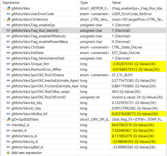
    This is really bizarre. because the output of checkIq2_A is not a squared value of Iq_A, also values of checkIs_A and gMotorVars.Is_A differ, but that I could probably account for receiving debug data at different timeslots. while the Iq2 squared does behave normal when Iq_A is below ~12

  • which version of CCS are you using?
    which effective compiler?
  • the checkIq2_A calculation is saturated overflow if you are using Q24 format, the maximum is +/-128, so the Iq_A need to be less than SQRT(128), is about 11.3.
  • I am using CCS 6.2.0.00050 and as Yanming35051 pointed I already managed to figure out the overflow of IQ24 values with values higher than 128. I still can;t figure out why at high speeds (in torque mode) the PWM duty does go from ~0% all the way up to ~100% duty, but in position control, the PWM never goes outside the 40-60% range, independent of the phase.
  • Maximum current is enough if it is saturated.