Other Parts Discussed in Thread: DRV8301
I've been trying to run a PMSM pump motor with the LaunchpadXL F28069 and BoostXL DRV8301 driver set for several days now, but so far unsuccessfully. I worked through the InstaSPIN FOC lab projects and only managed to configure the motor to produce unoptimized, eratic movements at times and having my motor heat up to extreme temperatures. The problem is that I cannot find the correct motor parameters and I only have limited information about the motor. I have seen the motor turn with stutters with some settings and a little smoother on the DRV8312-Dev-C-Kit, but I'm unable to reliably reproduce those results.
Motor specifications:
The device is a very small medical blood pump for implantation into the heart's left ventricle and the pump actually houses two PMSM motors that turn the magnetic impeller. You can see some technical drawings of the pump's internals in this patent application: www.google.de/.../US7976271
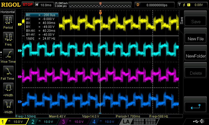
Recommended operation range is ca.1000-5000rpm. Unfortunately, there are no detailed motor specifications or datasheets available to me. The original manufacturer's control hardware measured power consumption of 3.8Watt at 2580rpm during proper operation. The following oscilloscope readout of the motor phases during the test with the original controller leads me to believe that the pump motors are rated for 12-15V:
I've previously tried to run the motor with the BoostXL boards with 24V, which explains the heat build-up. Changing to 12V, the first startup of the Launchpad board surprisingly provided the best result so far with 600rpm but still slow and extremely stuttery, but I'm unable to reproduce the result with identical configuration. (For this I used lab11d to run both motors in sync, I also managed to run a single motor smoothly at 1500-2500 rpm on the DRV8312-Dev-C-Kit on 24V with high heat production)
Motor Identification:
I used one of those cheap Chinese component testers with following results:
Rs=2.6Ohm
Ls=0.0004H
The identification process of labs02c/d give wildly different results. (Note: the identification was executed with the motor under load, i.e. the pump filled with water, since the impeller must be free-floating in a liquid medium). The pump never moves when running the identification process:
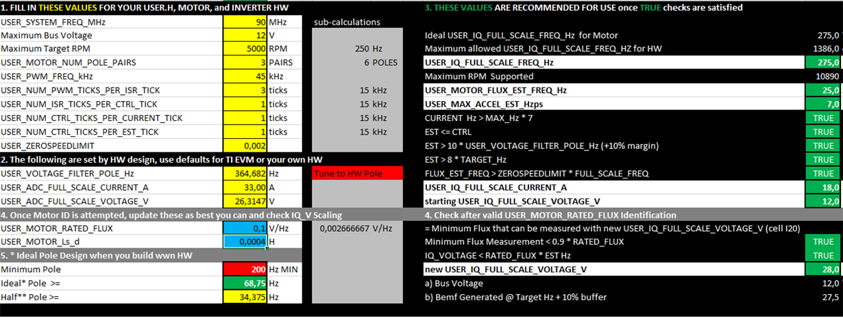
I used the motor config spreadsheet to calculate some system parameters:
#define USER_IQ_FULL_SCALE_FREQ_Hz (275.0)
#define USER_IQ_FULL_SCALE_VOLTAGE_V (94.0)
#define USER_IQ_FULL_SCALE_CURRENT_A (18.0)
#define USER_ADC_FULL_SCALE_CURRENT_A (33.0)
#define USER_PWM_FREQ_kHz (15.0)
#define USER_R_OVER_L_EST_FREQ_Hz (100.0)
#define USER_PWM_FREQ_kHz (45.0)
#define USER_MOTOR_TYPE MOTOR_Type_Pm
#define USER_MOTOR_NUM_POLE_PAIRS (3)
#define USER_MOTOR_Rr (NULL)
#define USER_MOTOR_Rs (NULL)
#define USER_MOTOR_Ls_d (NULL)
#define USER_MOTOR_Ls_q (NULL)
#define USER_MOTOR_RATED_FLUX (NULL)
#define USER_MOTOR_MAGNETIZING_CURRENT (NULL)
#define USER_MOTOR_RES_EST_CURRENT (2.0)
#define USER_MOTOR_IND_EST_CURRENT (-2.0)
#define USER_MOTOR_MAX_CURRENT (2.0)
#define USER_MOTOR_FLUX_EST_FREQ_Hz (25.0)
lab02c results:
Motor M1 (Red):
Rs=2.26 Ohm
Ls=1.658e-11 to 8.49e-9
Flux=0.3 to 0.7 VpHz
Motor M2 (Blue):
Rs=2.8 Ohm
Ls=3.3e-8 to 0.0164
Flux=0.67 to 1.33 VpHz
I've tried different combinations of those parameters as well as different values for PWM frequency and flux frequency, but most of the time the motors just produce a high-pitched noise without movement and warm up.
The best fairly reproducable result so far, where the rotor is kind of moving a step every few seconds, is with the follow configuration. But I don't know how that is supposed to help me achieve fluid motor operation. (I'm applying those shared defines to both M1, M2 motor defines)
#define USER_PWM_FREQ_kHz_COM (15.0)
#define USER_MOTOR_TYPE_SHARED MOTOR_Type_Pm
#define USER_MOTOR_NUM_POLE_PAIRS_SHARED (3)
#define USER_MOTOR_Rr_SHARED (NULL)
#define USER_MOTOR_Rs_SHARED (2.2)
#define USER_MOTOR_Ls_d_SHARED (0.0004)
#define USER_MOTOR_Ls_q_SHARED (0.0004)
#define USER_MOTOR_RATED_FLUX_SHARED (0.1)
#define USER_MOTOR_MAGNETIZING_CURRENT_SHARED (NULL)
#define USER_MOTOR_RES_EST_CURRENT_SHARED (2.0)
#define USER_MOTOR_IND_EST_CURRENT_SHARED (-2.0)
#define USER_MOTOR_MAX_CURRENT_SHARED (2.0)
#define USER_MOTOR_FLUX_EST_FREQ_Hz_SHARED (25.0)
#define USER_NUM_PWM_TICKS_PER_ISR_TICK_SHARED (2)
#define USER_PWM_FREQ_kHz_SHARED USER_PWM_FREQ_kHz_COM
#define USER_IQ_FULL_SCALE_FREQ_Hz_SHARED (275.0) // 800 Example with buffer for 8-pole 6 KRPM motor to be run to 10 KRPM with field weakening; Hz =(RPM * Poles) / 120
#define USER_IQ_FULL_SCALE_VOLTAGE_V_SHARED (94.0)
#define USER_ADC_FULL_SCALE_VOLTAGE_V_SHARED (26.314) // 26.314 boostxldrv8301_revB voltage scaling
#define USER_IQ_FULL_SCALE_CURRENT_A_SHARED (18.0) // 20.0 Example for boostxldrv8301_revB typical usage
#define USER_ADC_FULL_SCALE_CURRENT_A_SHARED (33.0) // 33.0 boostxldrv8301_revB current scaling
At this point, I'm just blindly trying out parameter configurations in hopes that some give improved feedback, but with little success.
Do you have any advice on what I could do different or in what ballpark the required motor parameters lie in terms of the pumps low power consumption, recommended speeds and the aforementioned measurement results?
Synchronous dual motor drive:
lab11d allows to drive the phases of two motors synchronously with a default shift of the pwm signal by a half period. Is it possible to change this shift to a full period? We compared the phases of the original controller and it appeared to drive the two motors with a full period phase shift. The "halfPeriod_cycles" variable in hal_2motors.c is referenced in several places, so would it be sufficient to only change the line "PWM_setPhase(objMtr->pwmHandle[0],(halfPeriod_cycles>>1));" for HAL_MTR2 and change it to "PWM_setPhase(objMtr->pwmHandle[0],(halfPeriod_cycles));" ? (Removing the binary right shift and therefore doubling the offset from half to a full period?)


