This thread has been locked.

If you have a related question, please click the "Ask a related question" button in the top right corner. The newly created question will be automatically linked to this question.

MSP430F5510 and USB

Other Parts Discussed in Thread: MSP430F5510, CODECOMPOSER, MSP430F5529

Hi,

We are developing a product using MSP430F5510. We want to be able to download code onto the internal flash via USB. I read a bit of the USB-BSL on TI site and guessing thta USB BSL is present on th uC by default and we should be able to use that.

Now, the MSP430 USB module requires a clock to serve a s a refernce for USB PLL. The on-chip USB BSL needs to know the reference frequency to configure the PLL. By default, it is able to detect the presence of only 4 frequencies on XT2: 4MHz, 8MHz, 12MHz, 24MHz. The problem is we are using a16MHz  external crystal for XT2. So, how do we make the USB BSL recogniz this clock frequency. Do we need to create a new USB BSL code and burn it onto the uC?


Thanks in advcance,

Amee

  • Yes, you need to modify the default BSL to run at 16MHz.  We have done this on our project.

    The BSL is compiled in IAR, and is small enough to compile using the kickstart version of IAR.  The problem we had when modifying the BSL was that when compiled it would not fit into the flash available for the BSL due to some changes in the IAR compiler.  So we ended up removing all speed options and just allowed 16MHz.

    Works fine.  I can package up my 16MHz project and send to you if you think it would be useful.

    However we have just now decided to change the crystal to 24MHz to allow the default BSL to work.  This enables our production line to program the devices over USB without having the modify the BSL first (which would require a JTAG programmer on the line).

    Hope this helps.

    Rob.


  • HELLO

    I recently developed a board containg USB. I am using an MSP430f5510. I want to program the msp directly using a simple usb cable of typeB.But when i connect it my PC it shows as an HDI device. Will i be able to program my msp using codecomposer studio using ony a simple usb cable connecting MSP430 with the PC? Has anyone tried it.

    Please tell me what should i do

    I have attached 4Mhz crystal on xt2

    and 32 mhz crystal on xt1

  • Mihir Jariwala said:

    HELLO

    I recently developed a board containg USB. I am using an MSP430f5510. I want to program the msp directly using a simple usb cable of typeB.But when i connect it my PC it shows as an HDI device. Will i be able to program my msp using codecomposer studio using ony a simple usb cable connecting MSP430 with the PC? Has anyone tried it.

    Please tell me what should i do

    I have attached 4Mhz crystal on xt2

    and 32 mhz crystal on xt1

    MSP430F55x USB devices can be flashed by USB BSL without any glue logic (XT2 4/8/12/24 MHz), just USB cable to PC. There is TI USB Firmware Upgrade Example (PC side) for USB BSL.

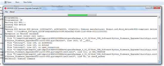
  • It's showing unknown command error when i try any of the sample examples

  • Never worked with Python version (only Win), so don't know about logs. Sample examples (included with USB BSL) are prepared for MSP430F5529 and they can't work with MSP430F5510 by default (except P1.0 blinking example).

    BTW, why you are using 32 MHz XT1 and 4 MHz XT2. All clocks can be sourced by XT2, and 24 MHz are supported by USB BSL. Also 32 MHz XT2 can be used, but (default) USB BSL will not work. USB will work also with 25 MHz XT2. Setup info is here...

    http://forum.43oh.com/topic/3904-usb-pll-configurator

  • You can try with Win version (more user friendly)...

    http://software-dl.ti.com/msp430/msp430_public_sw/mcu/msp430/MSP430_USB_Developers_Package/latest/index_FDS.html

    MSP430_USB_Firmware_Upgrade_Example-1.3.0-Setup.exe

    Install and start application, and select first prepared firmware Blink LED Example. Plug USB cable to PC with pressed BSL button on your board. Or press together reset and BSL button, first release reset and after 1 second release BSL button. If there is 4, 8, 12 or 24 MHz XT2 present, and everything is OK with board, Win will do enumeration, and Upgrade Firmware button will become enabled. Just press it and Blink LED Example firmware will be downloaded to your MSP430F5510 target device. If LED is present on P1.0 it will blink.

    For downloading your firmware, build project to TI txt format, select it with Select Firmware / Browse and flash it. If you want to try TI USB examples that are part of USB Dev Pack, than you must to rebuild them with selected MSP430F5510 as target (by default target is MSP430F5529).

  • Thank you for your assistance

    I tried the above mentioned method ad it shows the following. I did press the reset button and bsl button as you informed.

    Starting
    Password Sent Successfully
    Sending RAM BSL v00.07.07.37
    Done RAM BSL v00.07.07.37
    Failed to read data from RAM BSL
    Unsuccessful in starting the BSL. Restarting.
    Password Sent Successfully
    Sending RAM BSL v00.07.07.37
    Done RAM BSL v00.07.07.37
    Failed to read data from RAM BSL

    Please do revert back if you have any other suggestions

  • Mihir Jariwala said:

    Thank you for your assistance

    I tried the above mentioned method ad it shows the following. I did press the reset button and bsl button as you informed.

    Starting
    Password Sent Successfully
    Sending RAM BSL v00.07.07.37
    Done RAM BSL v00.07.07.37
    Failed to read data from RAM BSL
    Unsuccessful in starting the BSL. Restarting.
    Password Sent Successfully
    Sending RAM BSL v00.07.07.37
    Done RAM BSL v00.07.07.37
    Failed to read data from RAM BSL

    Please do revert back if you have any other suggestions

    Not sure about error, but probably there is problem with executing code from target device. On my DIY MSP430F5510 boards BSL log is...

    Starting
    Mass erase occured!
    Password Sent Successfully
    Sending RAM BSL v00.07.07.37
    Done RAM BSL v00.07.07.37
    Sending Blink LED code
    Firmware Sent
    Memory successfully verified
    Total programming time is 156ms
    Sending reset vectors
    Reset vector sent
    Interrupt reset successfully verified
    Resetting Device...
    Starting application
    Done!

  • Hi Zrno and Mihir,

    I have the similar problem even my console in firmware upgrade tool says the same.
    Starting
    Password Sent Successfully
    Sending RAM BSL v00.07.07.37
    Done RAM BSL v00.07.07.37
    Failed to read data from RAM BSL
    Unsuccessful in starting the BSL. Restarting.
    Password Sent Successfully
    Sending RAM BSL v00.07.07.37
    Done RAM BSL v00.07.07.37
    Failed to read data from RAM BSL

    I could able to load the blink exmple in firmware upgrade for first time and later taught to program with custom firmware. It did programmed for first time but showing the above error from later on.

    and also windows kept on saying usb device is malfunctioned and cannot be detected. Please help.

    Cheers,
    Sri.

  • Dear Sri,

    Initially I would request you to

    1. open Device Manager (If you are using Windows)
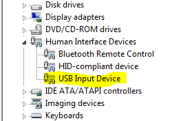
    2. Click on the drop down near Human Interface Device
    3. Connect your board using USB cable to the PC
    4. Check if two new entries are populated below ( ie HID-Compliant device, USB Input Device)
    5. If not press the Reset and BSL buttons together and remove and reinsert the usb cable into the PC(keep the nuttons pressed while inserting the cable intothe pc )
    6. After you have inserted the USB cable into the pc release the reset button first and then release the BSL button
    7. Check if two new entries are shown( ie HID-Compliant device, USB Input Device)
    8. Open USB Firmware upgrade and check if device is detected by the software
    9. Now try upgrading the firmware

    If it still show USB device is malfunctioned you need to check your connections(Check soldering and Connectivity of wires tracks)

    I faced the same problem and corrected it by checking the connections(ie. connections were loose).

    Hope this works.

    Mihir Jariwala

  • sri-sri said:

    I could able to load the blink exmple in firmware upgrade for first time and later taught to program with custom firmware. It did programmed for first time but showing the above error from later on.

    There is some problem with entering to USB BSL mode (BSL button). You was able to program it once (blink example) because device flash was empty ($FFFF), and device entered to USB BSL automatically (plugging to USB on PC) without any relation to BSL button.

    Mihir Jariwala said:

    5. If not press the Reset and BSL buttons together and remove and reinsert the usb cable into the PC(keep the nuttons pressed while inserting the cable intothe pc )

    6. After you have inserted the USB cable into the pc release the reset button first and then release the BSL button

    BTW, there is no need for unplugging/plugging USB cable to invoke USB BSL. It is enough to press together BSL and RESET button, release RESET button first, and after this release BSL button.

  • Hi Zrno and Mihir,

    Thank you so much for your quick replies.  After going through your suggestions, I have  fxed the problem. I can program using USB BSL now. I have also figured this out, I am writing this here so that some one might benefit from it.

    My laptop has 3 USB sockets one of them is ulta fast(I think) and the rest were a bit slow.  I could program this using ultra fast socket but not with the rest. I am not really sure about this, but this was the situation in my case. I have solved the problem any way. BUt some one of you can explain me the reason behind this, I will be very much happy.

    Thank you.
    Sri.

**Attention** This is a public forum