This thread has been locked.

If you have a related question, please click the "Ask a related question" button in the top right corner. The newly created question will be automatically linked to this question.

i2c bus is always busy

Other Parts Discussed in Thread: MSP430F4132, ENERGIA, MSP430F5438A

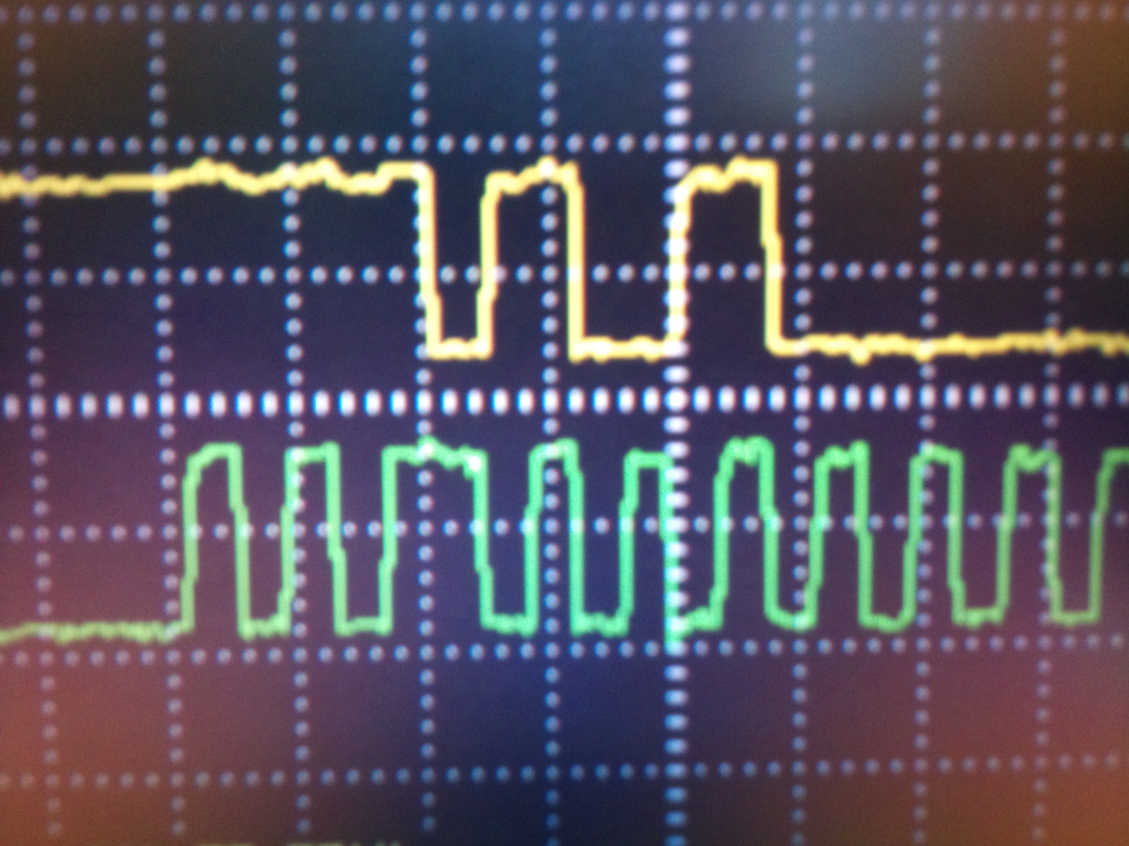
I'm trying to put the i2c device to work but the busy flag is always set. Checking the lines on the scope, both are high SCL and SDA. As soon the UCB0 config is done, the UCBUSY goes to Hi. What should it happening? Its configured as master, sync mode, by Smclk/11.

  • Ivan Santanna said:
    Checking the lines on the scope, both are high SCL and SDA. As soon the UCB0 config is done, the UCBUSY goes to Hi. What should it happening?

    You don't write which MSP you use.
    Do you configure the port pins for module usage? If not, they are still high-impedance inputs and the UCB0 is taliking against a (internal) wall.

  • Hello Jens. Thanks for your quick response...

    I'm using F4132, and yes, I'm setting the P6SEL for bits 1 and 2 as I2C device. See my configs bellow.

      UCB0CTL1 |= UCSWRST;                      // Enable SW reset
    P6SEL |= BIT1+BIT2; // seleciona I2C em P6.1 e P6.2
    UCB0CTL0 = 0x0F; // I2C Master, synchronous mode
    UCB0CTL1 = 0x81; // Use SMCLK, keep SW reset
    UCB0BR0 = 11; // fSCL = SMCLK/11 = 95.3kHz
    UCB0BR1 = 0;
    UCB0CTL1 &= ~UCSWRST; // Clear SW reset, resume operation
    
    
    I just have checked on the forum that some guys are having the same problem, but in my case, both lines are hi, and my pull-ups resistors are 10K.
    Thanks and best regards...
    
    
    Ivan
  • It's convenient (and make smistakes more obvious) to use the predefined symbols when configuring hardware.

    UCB0CTL0 = 0x0f; then turns into UCB0CTL0 = UCMODE_3|UCMST|UCSYNC; which is way more readable
    For UCB0CTL1, it would be UCSSEL_3|UCSWRST (or UCSSEL_SCMCLK|UCSWRST).

    It looks good so far.

    UCBBUSY should only be set if a start condition was detected (SDA going low while SCL was high)
    However, the configuration looks okay and as you say the lines are always high, so UCBBUSY shouldn't be set when clearing UCSWRST.
    I checked the device errata sheet, but no erratum is listed.

    If you're the only master on the bus, then maybe you can just ignore this. Or try to issue a STOP condition manually and see whether the busy bit clears.
    In opposition to teh SPI or UART mdoes, in I2C mdoe this bit signals that a START condition has been detected on teh bus and clears when a STOP is detected. It doe snot signal the completion of a transfer, so if you're the only master, it's rather a don't care (who if not you would allocate the bus if you're the only master?)

  • Jens, I already tried to force a STOP condition and check the busy flag. Actually, everything still the same, and nothing occur on the bus, neether the stop condition. 

    I'm not using interrupt on this application, and I think that I should use the busy flag only to wait for the I2C machine to be ready. See my code below (sorry for the comments in portuguese):

    // Rotina TX I2C //
    void TxI2C(unsigned char DevAddr, unsigned char ByteCnt){

    P1OUT ^= 0x02; // only for debug

    UCB0I2CSA = DevAddr; // carrega endereço do dispositivo slave

    Pt_BuffI2C = (unsigned char *)BuffI2C; // coloca apontador no incio do buffer i2c

    UCB0CTL1 |= UCTR + UCTXSTT; // seta transmissão e gera START

    while (UCB0STAT&0X10); // aguarda ack do start bit com device addres THE CODE STOPS HERE.

    while (ByteCnt--) // Check TX byte counter
    {
    while (UCB0STAT&0X10); // aguarda enquanto maquina ocupada
    UCB0TXBUF = *Pt_BuffI2C++; // Load TX buffer
    }

    UCB0CTL1 |= UCTXSTP; // I2C stop condition

    while (UCB0STAT&0X10); // aguarda ack do start bit com device addres

    P1OUT ^= 0x02; // only for debug

    }

    So if I should ignore the busy flag, what's the way to check the I2c availability to know if a new byte can be sent?

    Thanks and regards...

    Ivan

  • Ivan Santanna said:
    what's the way to check the I2c availability to know if a new byte can be sent

    I2C is a transaction-based bus. Each transaction ahs a start and stop condition and an arbitrary number of byte transfers in-between. If you're the only I2C master ont eh bus, the oly one who can start a transaction is you. The busy bit only indicates whether a transaction start has been detected and no transaction end has happened yet. But if you're the only one who can start a transaction, who cares?

    To check whether the next byte can be sent during a transaction, there is the TXIFG bit. It tells you that the output buffer is free to receive the next byte. You can then either put a new byte in that will be sent when possible, ot set the UCSTP bit, which will send a stop condition once the currently transmitted byte is through. To check whether the I2C transaction is completed, you then test for the UCSTP bit become cleared again.

    The 5x family users guide contains a really good diagram what will happen when during an I2C transaction. It is identical for the 2x and 4x family USCI modules (even though the 2x and 4x family USCIs have slightly different registers and interrupt vectors than the 5x USCIs)

  • Hi Ivan, Please post full content of register UCB0STAT, IE2 IFG2.

     IFG2 bit RX and TX are both clear?

    Ivan Santanna said:

    I'm using MSP430F4132, and yes, I'm setting the P6SEL for bits 1 and 2 as I2C device. See my configs below.

     UCB0CTL1 |= UCSWRST; // Enable SW reset
    P6SEL |= BIT1+BIT2; // seleciona I2C em P6.1 e P6.2
    UCB0CTL0 = 0x0F; // I2C Master, synchronous mode
    UCB0CTL1 = 0x81; // Use SMCLK, keep SW reset
    UCB0BR0 = 11; // fSCL = SMCLK/11 = 95.3kHz
    UCB0BR1 = 0;
    UCB0CTL1 &= ~UCSWRST; // Clear SW reset, resume operation

    I remember somewhere I read to move the reset on first line and release on last,

     UCB0CTL1 = 0x81; // Use SMCLK, keep SW reset
    P6SEL |= BIT1+BIT2; // seleciona I2C em P6.1 e P6.2
    UCB0CTL0 = 0x0F; // I2C Master, synchronous mode
    UCB0BR0 = 11; // fSCL = SMCLK/11 = 95.3kHz
    UCB0BR1 = 0;
    UCB0CTL1 &= ~UCSWRST; // Clear SW reset, resume operation

    Regards

  • 6557.tie2eCrash.zip Why this forum is so SLOW and need to edit many times before to remove artifact?

     A crash report to clarify why :(

     Second time edit to insert again file ....

  • Roberto Romano said:
    I remember somewhere I read to move the reset on first line and release on last,

    Yes. That's what he did. The first(yellow) lien sets SWRST, the green one keeps it set while switching over to SMCLK, and the last line clears it. Nothing wrong.
    It's even better than settign SWRST and changing the clock in one line. It might not make a difference in thsi case, but on some modules, the additional changes are simply ignored when a certain 'enable' bit wasn't set prior to the change.

    However, it might be better to configure the the operation mode (in UCB0CTL0) before switching the port pins (to avoid glitches on the output)

    But none of this explains why UCBUSY is set.

  • Jens-Michael Gross said:

    However, it might be better to configure the the operation mode (in UCB0CTL0) before switching the port pins (to avoid glitches on the output)

    But none of this explains why UCBUSY is set.

     I agree with you, status register can be of some use if sampled also before and after release SWRESET bit to see if it was high or become high and or some other error condition exist. generating a start condition on bus must also set arbitration lost bit.
     Regards
  • Hello All.

    First of all, thanks everybody for support me.

    Actually, I found my problem. I tried to write an I2C code and the SDA line was not working (always high, because of the pull-ups). Then I found a bad soldering pad under the QFN package. I fixed this hardware bug and the I2C hardware become to work properly.

    Thanks again...

    Ivan

  •  Good, please check verify answer button to mark this problem solved. (button can be pressed more than one time across thread for every solution apply).

     Regards

  • Hi Roberto, sorry but that's my first time on this forum, and I cannot find this button to mark this problem as solved...

  •  Hi Ivan, the verify answer you hit mark this problem as answered so as a solution is found. As you see you can check more than one time, check raise the level of person that receive answer, unchecking drop level point to that person.

     Regards

     Roberto

  • Roberto Romano said:
    check raise the level of person that receive answer

    Only the first verified answer gets points. But I don't know whether it is the first one checked in the order of checking or tin the order of appearance in the thread.

    If I had gotten all the points from threads where I provided an answer (or more than one when the topic changed or extended) and got not verify mark or got it as second in line, I guess I'd be nearing the 100k points now. :)

    Roberto Romano said:
    unchecking drop level point to that person

    And the next one gets the points.

  • Jens-Michael Gross said:
    check raise the level of person that receive answer

    Only the first verified answer gets points. But I don't know whether it is the first one checked in the order of checking or tin the order of appearance in the thread.[/quote]

     Wow guru error :D Not really Jeans, probably on old forum was, when I checked all answer in my question, for every one of your answer you got 20 pt each ;)

    Jens-Michael Gross said:
    unchecking drop level point to that person

    And the next one gets the points.[/quote]

     Never done that, I prefer never use that function, is better to leave a question as answered than lower point to a member.

     Regards

     Roberto

  • Roberto Romano said:
    Wow guru error :D Not really Jeans, probably on old forum was, when I checked all answer in my question, for every one of your answer you got 20 pt each ;)

    Well, that was teh description of how points are awarded, the last time I read it. If the forum software has changed this silently since...

    I just re-read teh explanations and indeed, teh 'only the firs tperson gets th epoints' phrase has been removed. However, the FAQ reads 'Verified answers can be selected by any community member.', which isn't true unless I misinterpret it. One can only veryfy answers if one  has started the thread (or is a moderator?)

    YOu may call it paranoia, but I din't trust any statement of a list anymore, if only one of them is obviously untrue. Even if it is just my interpretation that's wrong, it would mean that my interpretations of the others might be wrong too. :)

    Roberto Romano said:
    I prefer never use that function, is better to leave a question as answered than lower point to a member.

    Well, I didn't start many threads (only three or so in the two years), so I'm not tempted :)

    But the main reason for thsi flag is nto to award poiints, it is to mark replies that contain the answer, for easy identification. (and, of course, to mark the thread as having an answer).
    If a post doe snto contain an answer (only 'I found the error but won't tell you'), this thread does not contain an answer and therefore the post shoudl be un-verified (which could be done, however, only by the one who verified it, ort  amoderator). If the thread opener marks his own post as verified, he won't get points for it anyway.
    But even if a post that seemed to contain the answwer, later turns out to not being the answer to the problem, it should be unverified. Just to not guide people who read this thread later into the idea that this thread would be the answer while it wasn't. Causing them perhaps more trouble than never reading the thread at all.

  • Hello Jens-ichael and Roberto. Does anybody know why the I2C wave form on MSP430F4132 has two clock pulses before the start bit? Look the picture attached...

    Thanks and best regards...

    Ivan

  •  Hi Ivan, I suppose clock is the green trace, so Data line is High and clock low, bus is in unknown state, first transacton is a start the second the stop, after then the bus is in a known idling state.

     The question is why clock is in a low state?

     Ivan, your actual score is 90, just to test please note our score then check all verify answer in this forum thread.

     Regards

     Roberto

  • Ivan Santanna said:
    Does anybody know why the I2C wave form on MSP430F4132 has two clock pulses before the start bit?

    I think Roberto is on the right trace..

    It looks liek the first two clock pulses, along with the low line before the first, are caused by port pin and USCI initialization and no real clock pulses. However, the clock pulse before the start condition is necessary to validly have a high data line (allowing other peers to release SDA while clock is low) before releasing clock and then pulling data low while the clock is high.

  • Hello, I don't think I have a soldering problem like the original poster had, but I am still getting UCBBUSY as soon as I deassert RST.  I read slau208m.pdf section 39.3.5.2 multiple times, but I don't see what I am doing wrong.  I am tired, so I will hook up the scope to SCL and SDA tomorrow.  If someone can comment on my approach as a sanity check, I would appreciate it very much.  Reading slau208m.pdf page 1046, I don't see how anything will work when the BUSY bit is stuck high all the time: "The eUSCI_B module waits until the bus is available, then generates the START condition, and transmits the slave address."

    My code is broken up into 3 sections: initialization, writing a 0 data message (reset) as a master, and finally reading 4 bytes as a master.  I am talking to a Honeywell RH sensor, as described in "I2C Comms HumidIcon TN_009061-2-EN_Final_07Jun12.pdf".  

    Initialization:

    //See slau208m.pdf Figure 36-13
    //UCB0BR1 = 0;
    UCB0BR0 = SMCLK_HZ/100000U;// = SMCLK/fSCL, fSCL = 100 KHz in standard mode
    //The only I2C slave uC will talk to is HIH6121-021-001; so hard code addr
    UCB0I2CSA = 0x27;//burned into HIH6121-021-001 IC; only talk to 1 slave
    //UCB0IE |= UCRXIE;// Enable RX interrupt
    P3SEL |= BIT2 | BIT1;// Assign I2C pins to USCI_B0
    UCB0CTL1 = UCSSEL_2// Use SMCLK,
    | UCTR //uC is the sender of the wake up message
    | UCTXSTP//AND Generate STOP right away, in the same frame
    | UCSWRST//keep I2C in reset
    ;
    Writing a reset message (Honeywell doc calls this the conversion start request)
    //Honeywell datasheet:
    //Measurement Request command to I2C slave: consists of the Slave
    //address plus the WRITE bit (0). Once the sensor responds with an
    //acknowledge (ACK), the Master (SHOULD) generates a stop condition.
    //slau208m.pdf, I2C Master Transmitter Mode:
    //After initialization, master transmitter mode is initiated by writing
    //the desired slave address to the UCBxI2CSA register (already done in
    //BSP_init), selecting the size of the slave address with the UCSLA10
    //bit, setting UCTR for transmitter mode, and setting UCTXSTT to
    //generate a START condition. ... UCTXIFG bit is set when the START
    //condition is generated and the first data to be transmitted can be
    //written into UCBxTXBUF. As soon as the slave acknowledges the address,
    //the UCTXSTT bit is cleared. ... Setting UCTXSTP generates a STOP
    //condition after the [NEXT] acknowledge from the slave. If UCTXSTP is
    //set during the transmission of the slave's address ..., a STOP is
    //generated, even if no data was transmitted to the slave.
    //UCB0CTL1 &= ~UCSWRST;// Clear SW reset, resume operation
    //Wakeup message: I2C Comms HumidIcon TN_009061-2-EN_Final_07Jun12.pdf Figure 2
    UCB0CTL1 &= ~UCSWRST;
    __delay_cycles(10);
    //This is the repeated start (restart) shown in slau208m.pdf Figure 39-7
    UCB0CTL1 |= UCTR //uC is the sender of the wake up message
    | UCTXSTT//Generate a START condition
    | UCTXSTP//AND Generate STOP right away, in the same frame
    ;

    Reading data (62.5 ms later)

     //Wait till the slave acknowledges the address
    for(i=0; (UCB0CTL1 & UCTXSTT) && i < 0xFF; ++i)
    __delay_cycles(1);
    if(i == 0xFF) { // Problem reading RH sensor; indicate problem status
    //See I2C Comms HumidIcon TN_009061-2-EN_Final_07Jun12.pdf page 2
    raw_rh_reading[0] = 0xC0;//2 MSb is the status. b'00 means normal
    UCB0CTL1 |= UCSWRST;//give up
    } else {
    //uC is the receiver of the data; slave address stays the same
    UCB0CTL1 = UCSSEL_2// Use SMCLK,
    | UCTXSTT//Generate start
    ;
    for(j=0; j < 3; ++j) {
    for(i=0; !(UCB0IFG & UCRXIFG) && i < 0xFF; ++i)
    __delay_cycles(1);
    if(i == 0xFF) { // Problem reading RH sensor; indicate problem status
    //See I2C Comms HumidIcon TN_009061-2-EN_Final_07Jun12.pdf page 2
    raw_rh_reading[0] = 0xC0;//2 MSb is the status. b'00 means normal
    UCB0CTL1 |= UCSWRST;//give up
    break;
    }
    raw_rh_reading[j] = UCB0RXBUF;
    }
    if(j == 3) {//successful so far
    UCB0CTL1 |= UCTXSTP;//Generate a NACK and STOP after next byte
    for(i=0; !(UCB0IFG & UCRXIFG) && i < 0xFF; ++i)//wait for last byte
    __delay_cycles(1);
    if(i == 0xFF) // Problem reading RH sensor; indicate problem status
    raw_rh_reading[0] = 0xC0;//2 MSB is the status. b'00 means normal
    else//Good reading
    raw_rh_reading[3] = UCB0RXBUF;
    UCB0CTL1 |= UCSWRST;//stop I2C
    }
    }

  • USCI init:
    setting clock source (you do it?) and baudrate divider needs to be done while SWRST is set. (so the UCB0CTL1 assignment should be the first in the init process, even though after power-on SWRST is already set.)
    Setting the IE bits must be done after SWRST is cleared.
    Writing the slave address can be done any time, I think.
    The port pins should be configured before SWRST is cleared, or else the USCI might falsely detect a busy bus by detecting a signal change caused by the port pin init.

    Setting start and stop bit at the same time will not send nor receive anything. It Is only useful to check UCNACKIFG after the two bits are clear again, to see whether the device is present or not.
    Your waiting for loop is okay for a timeout, but even if there is no timeout, the start may still have failed. You need to check UCNACKIFG as well.

    Did your scope check reveal anything?

  • Yes, the scope revealed that SDA was stuck at 0.5 V.  I realized the importance of SDA being high, and its connection to UCBBUSY flag.  slau208m.pdf chapter 36 only makes a vague reference to UCBBUSY being the cause of things not working.  I inferred that from I2C Master Transmitter section introduction: "The USCI module checks if the bus is available, generates the START condition..."   Another FW engineer, who uses Arduino/Energia library to use the I2C (as supposed to the bare metal C like I was doing) thought I was reading tea-leaves, but I think I was right, based on the working result (below):

    Despite the pull-up resistor next to the I2C sensor, something on the MSP430F5438A apparently trying to pull it down.  That's why it worked the 1st time from power up, but not after that.  I did the combination of the following things to work around the problem:

    1. Turn off the I2C peripheral when not in use: UCB0CTL1 |= UCSWRST;; P3SEL &= ~(BIT2 | BIT1);
    2. Remove power to the I2C sensor when not in use
    3. Change SDA and SCL to GPIO out, and shake it up and down a few times after done with I2C.  This trick is based on this e2e post.

    I don't change UCB0CTL0, UCB0BR0, and UCB0I2CSA after configuring it EVER.

    You CAN send UCTXSTT and UCTXSTP in the SAME frame.  That is what is shown in the sensor datasheet as the message to kick the sensor to begin conversion (see attached sensor datasheet).3058.I2C Comms HumidIcon TN_009061-2-EN_Final_07Jun12.pdf

  • Well, wiggling SDA and SCL will generate a variety of start and stop conditions. If SCL is high, the slave may not change its SDA output state. If it is low for some reason, it remains low. Which prevents a start condition etc.

    Perhaps it helps if you just manually generate a stop. SCL low, SDA low, SCL high, SDA high. With GPIO. Well, not setting the GPIO output to active high but rather by switching between low output and input.

    But normally, if a transfer succeeded, the next should not be blocked. (except for the erratum of the next start after a stop being perhaps sent too fast)

    Yes, you can set UCTXSTT and UCTXSTP simultaneously. This will send a start byte and a stop. In TR mode, this will be used as a ‘ping’ as you get UCNACKIFG set if the slave didn’t answer. It may, however, cause the slave to assume a ‘0’ byte sent as internal address, so it may disturb the internal register pointer of the slave. Some slaves take it as reset. One should know the slave before using this. In your case it is indeed a trigger, and the sensor doesn’t support writing data to it at all (only read). But that's a rather uncommon case.

    That’s why I don’t like library functions. They make things (like the ‘slave there?’ check) and nobody notices the side-effects.

**Attention** This is a public forum