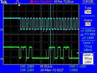
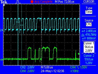
Hello,
In my design, I am currently using an MSP430F5309 to communicate with an MPU-6050 sensor by Invensense: http://invensense.com/mems/gyro/sixaxis.html
I am using the USCI in I2C Mode, and I used the sample code as a guideline. My intent is to use a Timer to read the sensors via I2C every X ms (let's say for example, every 20 ms, or 50 Hz). I tried to implement this using TimerA0, and having the MSP430 operate in LPM0.
I have the following problem. Before entering LPM0, I do some writing and reading via I2C. This works out fine, as I expected. However, after entering LPM0, it seems as if the system no longer enters the I2C interrupt. My code is shown below:
-------------------------------------------------
#include <msp430f5310.h>
volatile static const unsigned char MPU6050_ADDR = 0x68;
volatile static unsigned char *PTxData; // Pointer to Tx data
volatile static unsigned char TxByteCtr;
volatile static unsigned char TxData[256];
volatile static unsigned char Temp;
volatile static unsigned char WhoAmI = 0;
volatile static unsigned char TestReg1 = 0;
volatile static unsigned char TestReg2 = 0;
volatile static unsigned char TestReg3 = 0;
volatile static unsigned char RxByteCtr;
volatile static unsigned char RxData[256];
volatile static unsigned char RxByteDummy;
volatile static signed int Accel[3];
volatile static unsigned char Accel_Buffer[6];
volatile static signed int Gyro[3];
volatile static unsigned char Gyro_Buffer[6];
volatile static unsigned char ReadWrite = 0;
volatile static unsigned int Period = 655;
volatile static unsigned char I2C_Stop_Flag = 0;
void I2C_Send(unsigned char length, unsigned char addr);
void Initialize_MPU6050(void);
unsigned char MPU6050_Read_Register(unsigned char TX);
void MPU6050_Read_Sensors(void);
void main(void)
{
WDTCTL = WDTPW + WDTHOLD; // Stop WDT
UCSCTL4 |= SELA_2; // Set ACLK = REFO
// Initialize I2C Port
P4SEL |= 0x06; // Assign I2C pins to USCI_B1
UCB1CTL1 |= UCSWRST; // Enable SW reset
UCB1CTL0 = UCMST + UCMODE_3 + UCSYNC; // I2C Master, synchronous mode
UCB1CTL1 = UCSSEL_2 + UCSWRST; // Use SMCLK, keep SW reset
UCB1BR0 = 10; // fSCL = SMCLK/10 = ~100kHz
UCB1BR1 = 0;
UCB1I2CSA = 0x68; // Slave Address is 068h
UCB1CTL1 &= ~UCSWRST; // Clear SW reset, resume operation
UCB1IE |= UCTXIE + UCRXIE; // Enable TX interrupt
// Initialize MPU-6050
__enable_interrupt();
Initialize_MPU6050();
WhoAmI = MPU6050_Read_Register(0x75);
TestReg1 = MPU6050_Read_Register(0x6B);
TestReg2 = MPU6050_Read_Register(0x1B);
TestReg3 = MPU6050_Read_Register(0x1C);
MPU6050_Read_Sensors();
__disable_interrupt();
P6DIR |= 0x04; // P6.2 output
TA0CCTL0 = CCIE; // CCR0 interrupt enabled
TA0CCR0 = 50000;
TA0CTL = TASSEL_1 + MC_2 + TACLR; // ACLK, Continuous Mode, clear TAR
__bis_SR_register(LPM0_bits + GIE);
}
//------------------------------------------------------------------------------
// The USCIAB1TX_ISR is structured such that it can be used to transmit any
// number of bytes by pre-loading TxByteCtr with the byte count. Also, TXData
// points to the next byte to transmit.
//------------------------------------------------------------------------------
#pragma vector = USCI_B1_VECTOR
__interrupt void USCI_B1_ISR(void)
{
switch(__even_in_range(UCB1IV,12))
{
case 0: break; // Vector 0: No interrupts
case 2:
__no_operation();
break; // Vector 2: ALIFG
case 4:
__no_operation();
break; // Vector 4: NACKIFG
case 6: break; // Vector 6: STTIFG
case 8: break; // Vector 8: STPIFG
case 10: // Vector 10: RXIFG
RxByteDummy = UCB1RXBUF; // Move final RX data to PRxData
if (RxByteCtr == 1) {
RxByteCtr--; // Increment RX byte counter
RxData[RxByteCtr] = RxByteDummy;
UCB1CTL1 |= UCTXSTP; // I2C stop condition
UCB1IFG &= ~UCTXIFG; // Clear USCI_B1 TX int flag
UCB1IFG &= ~UCRXIFG; // Clear USCI_B1 RX int flag
I2C_Stop_Flag = 1;
}
else {
__no_operation();
}
__no_operation();
break;
case 12: // Vector 12: TXIFG
if (!ReadWrite)
{
if (TxByteCtr) // Check TX byte counter
{
UCB1TXBUF = *PTxData++; // Load TX buffer
TxByteCtr--; // Decrement TX byte counter
}
else
{
UCB1CTL1 |= UCTXSTP; // I2C stop condition
UCB1IFG &= ~UCTXIFG; // Clear USCI_B1 TX int flag
I2C_Stop_Flag = 1;
}
}
else {
if (TxByteCtr) // Check TX byte counter
{
UCB1TXBUF = *PTxData++; // Load TX buffer
TxByteCtr--; // Decrement TX byte counter
}
else {
UCB1CTL1 &= ~UCTR;
UCB1CTL1 |= UCTXSTT;
}
}
default: break;
}
}
void I2C_Send(unsigned char length, unsigned char addr)
{
PTxData = (unsigned char *)TxData; // TX array start address
// Place breakpoint here to see each
// transmit operation.
TxByteCtr = length; // Load TX byte counter
UCB1I2CSA = addr;
I2C_Stop_Flag = 0;
UCB1CTL1 |= UCTR + UCTXSTT; // I2C TX, start condition
__no_operation();
while (!I2C_Stop_Flag); // Ensure stop condition got sent
__no_operation();
}
void Initialize_MPU6050(void)
{
TxData[0] = 0x6B; TxData[1] = 0x01; // Power Management Register
unsigned char Buffer_Size = 2; ReadWrite = 0;
I2C_Send(Buffer_Size, MPU6050_ADDR);
__no_operation();
Buffer_Size = 2; ReadWrite = 0;
TxData[0] = 0x1B; TxData[1] = 0x08; // Gyro Range Register
I2C_Send(Buffer_Size, MPU6050_ADDR);
__no_operation();
Buffer_Size = 2; ReadWrite = 0;
TxData[0] = 0x1C; TxData[1] = 0x18; // Lin Acc Range Register
I2C_Send(Buffer_Size, MPU6050_ADDR);
__no_operation();
}
// Timer0 A0 interrupt service routine
#pragma vector=TIMER0_A0_VECTOR
__interrupt void TIMER0_A0_ISR(void)
{
P6OUT ^= 0x04; // Toggle P6.2
MPU6050_Read_Sensors();
TA0CCR0 += Period;
}
unsigned char MPU6050_Read_Register(unsigned char TX)
{
RxByteCtr = 1;
unsigned char Buffer_Size = 1;
TxData[0] = TX;
ReadWrite = 1;
for (int i=0;i<10;i++); // Delay required between transaction
I2C_Send(Buffer_Size,MPU6050_ADDR);
ReadWrite = 0;
for (int i = 0; i < 10; i++); // Delay required between transaction
return RxData[0];
}
void MPU6050_Read_Sensors(void)
{
Accel_Buffer[0] = MPU6050_Read_Register(0x3B);
Accel_Buffer[1] = MPU6050_Read_Register(0x3C);
Accel_Buffer[2] = MPU6050_Read_Register(0x3D);
Accel_Buffer[3] = MPU6050_Read_Register(0x3E);
Accel_Buffer[4] = MPU6050_Read_Register(0x3F);
Accel_Buffer[5] = MPU6050_Read_Register(0x40);
for (int j = 0; j < 6; j = j + 2)
{
Accel[j >> 1] = (((signed int)Accel_Buffer[j]) << 8) | Accel_Buffer[j+1];
}
Gyro_Buffer[0] = MPU6050_Read_Register(0x43);
Gyro_Buffer[1] = MPU6050_Read_Register(0x44);
Gyro_Buffer[2] = MPU6050_Read_Register(0x45);
Gyro_Buffer[3] = MPU6050_Read_Register(0x46);
Gyro_Buffer[4] = MPU6050_Read_Register(0x47);
Gyro_Buffer[5] = MPU6050_Read_Register(0x48);
for (int j = 0; j < 6; j = j + 2)
{
Gyro[j >> 1] = (((signed int)Gyro_Buffer[j]) << 8) + Gyro_Buffer[j+1];
}
}
-------------------------------------------------
I would greatly appreciate any assistance anyone can provide.
Sincerely,
Mehdi


