• Join
  • Sign In with my.TI Login
Texas Instruments
  • Products
  • Applications
  • Tools & Software
  • Support & Community
  • Sample & Buy
  • About TI
Sample & Purchase Cart Sample & Purchase Cart
  • Search
  • Advanced
TI E2E™ Community
  • Support Forums
  • Blogs
  • Groups
  • Videos
  • 简体中文
  • More ...
TI Home » TI E2E Community » Support Forums » Microcontrollers » MSP430™ Microcontrollers » MSP430 Ultra-Low Power 16-bit Microcontroller Forum » 9V battery check with MSP430F4351, no ADC, no comparator
Share
MSP430™ Microcontrollers
  • Forum
  • Announcements
  • E2E Wiki
Options
  • Subscribe via RSS
MSP430 Resources
  • MSP430 Product Folder
  • MSP-EXP430G2 - MSP430 LaunchPad Value Line Development kit
  • MSP430 Getting Started Guide
  • MSP430 Microcontroller Projects
  • More Resources >
  • 9V battery check with MSP430F4351, no ADC, no comparator

    9V battery check with MSP430F4351, no ADC, no comparator

    This question is answered
    Bruno Marchesi
    Posted by Bruno Marchesi
    on Jun 06 2012 08:22 AM
    Prodigy220 points

    Hello,

    3V3 power comes from 9V standard battery. It's a temperature measurement tool, 
    shaped as a pistol, with a trigger. So the hardware is always powered down,
    when the trigger is pressed the 9-3V3 regulator is kept on by a MSP keepalive signal
    to this regulator  shutdown pin.

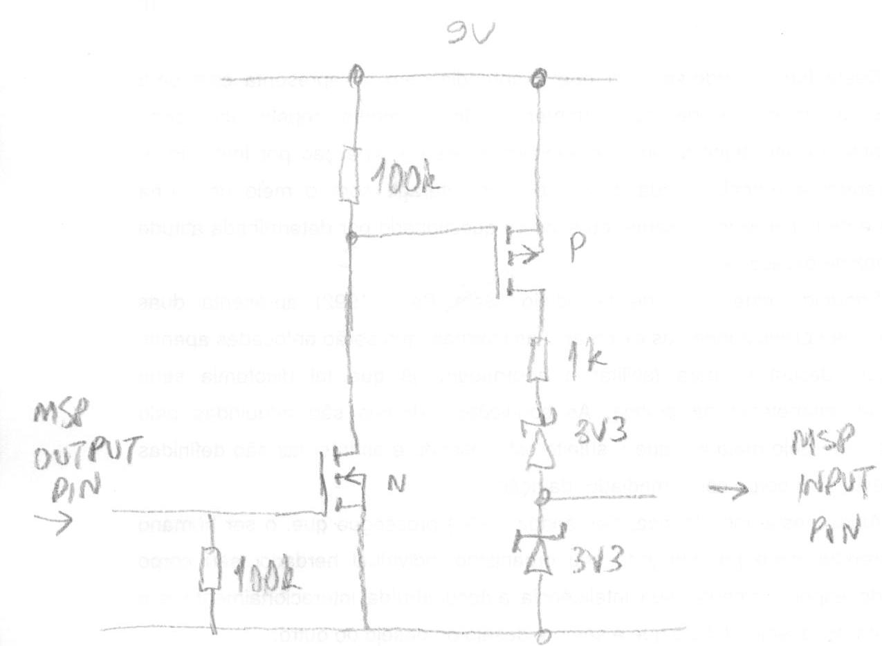
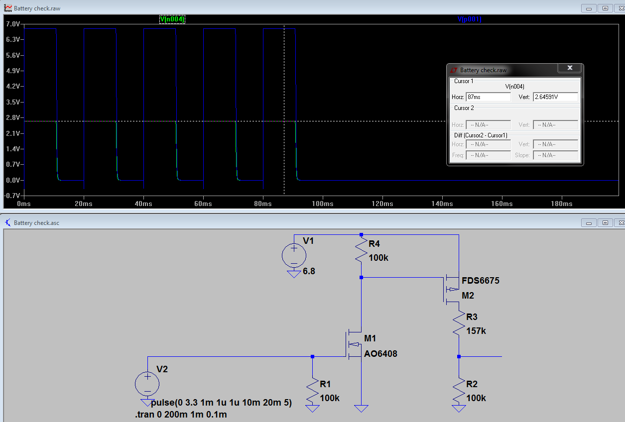
    Ok, the problem is we need a low bat check. There's no ADC, the comparator input
    is already in use. This level check should draw 5nA top, but preferably be in
    shutdown mode and turned on only when the MSP wants to inquire it if everything
    is shining with the battery level.

    I'm wondering about using a commercial vco to do this. Since this 
    is far from a new problem, I'd ask if someone could please share his/her thoughts about this?

    Thanks in advance,
    Xezi. 

    battery
    Report Abuse
    • Reply
    You have posted to a forum that requires a moderator to approve posts before they are publicly available.
    All Replies
    • old_cow_yellow
      Posted by old_cow_yellow
      on Jun 06 2012 09:48 AM
      Guru25775 points

      I think 3V3 power comes from 9V standard battery is not a good choice. Take a look at size/Joule, weight/Joule, and cost/Joule. 9V standard battery is mostly used where you need the voltage and do not want to bother with a DC-DC converter and do not care about energy.

      Report Abuse
      • Reply
      You have posted to a forum that requires a moderator to approve posts before they are publicly available.
    • Bruno Marchesi
      Posted by Bruno Marchesi
      on Jun 06 2012 11:36 AM
      Prodigy220 points

      Well, yes, we were aware of this, but the 9V bat could not be changed in this particular
      design. Though we could improve the energy efiiciency, that's not of concern.  The 
      difficulty really stands in knowing the battery condition - we don't even need to know
      its voltage, only if it's still 'good' or 'bad', if needs to be replaced.

      Thank you for your reply. 

      Report Abuse
      • Reply
      You have posted to a forum that requires a moderator to approve posts before they are publicly available.
    • Andy Neil
      Posted by Andy Neil
      on Jun 06 2012 14:05 PM
      Guru31975 points

      Bruno Marchesi
      the comparator input is already in use

      could you add an analogue mux/switch to it...?


      Report Abuse
      • Reply
      You have posted to a forum that requires a moderator to approve posts before they are publicly available.
    • Bruno Marchesi
      Posted by Bruno Marchesi
      on Jun 06 2012 15:10 PM
      Prodigy220 points

      Yes, an analog switch could be used, as a bit of an expensive
      solution, I believe. 
      We could do: 9V - R1  - AS input - R2 - Qs - GND
      AS stands for analog switch. 

      R1-R2 provides the voltage drop from 9V to, say, Vcc/2,
      to be read from the MSP compare pin.

      Qs base is tied to a MSP I/O pin. This way, whenever
      the MSP powers off, additional current drawing from the
      9V R1-R2 net is minimized.

      We need an analog switch with nA quiescent current,
      or a shutdown pin that gives us that condition.  Two ADG701
      appear to do the job, although I sometimes still got puzzled
      with parameters like "1nA typ/1uA max quiescent current",
      in the sense this is a 1,000 fold range. If it stays around 1nA,
      I believe this could be done.

      I still wonder if a 2x $3 part would be a good solution in this case,
      meaning if there isn't a better, more straightforward approach,
      which I really can't see right now.


      Thank you for your reply. 

      battery analog switch
      Report Abuse
      • Reply
      You have posted to a forum that requires a moderator to approve posts before they are publicly available.
    • Peter Dvorak
      Posted by Peter Dvorak
      on Jun 07 2012 04:19 AM
      Expert1540 points

      Hi Bruno,

      Are you sure of this 5nA requirement?

      A standard 9V battery has 400mAh capacity.

      At 5nA it will drain in 100 years (0.4  /  5e-9 *24*365 =9132 years)

      Peter

      Report Abuse
      • Reply
      You have posted to a forum that requires a moderator to approve posts before they are publicly available.
    • Bruno Marchesi
      Posted by Bruno Marchesi
      on Jun 07 2012 08:09 AM
      Prodigy220 points

      Hi Peter,

      no, I'm not sure. The current drain and battery lifetime calculations I've made
      are not precise. I've measured the on and off state current drawings with an Agilent 34410,
      and I'd conduct tests once the product is first assembled to get better aproximations.

      The last data I've got  is 120mAh for local market 9V batteries, and
      with around 50-100nA continuous current consumption plus the
      on state usage - reaches 20-40mA, a lifetime of around 2 years.  
      We were looking to something around 5 years, which is the usual
      battery expire time, considering you've buyed it  soon enough.

      Not sure if I'm overreacting with this battery draining thing.  

      Thank you for your reply.

      battery
      Report Abuse
      • Reply
      You have posted to a forum that requires a moderator to approve posts before they are publicly available.
    • Jens-Michael Gross
      Posted by Jens-Michael Gross
      on Jun 08 2012 09:45 AM
      Guru140530 points

      Bruno Marchesi
      We could do: 9V - R1  - AS input - R2 - Qs - GND

      Why not using 9V - R1 - FET - MSPin - R2 - GND?
      Teh FET is controlled by an MSP pin. Since the FET gate is a pure capacitive load, the port pin won't drive any current except during state change.
      When you raise the gate of the FET to VCC, the MSP input pin will raise from GND (through R2) to (R1*R2)/(R1+R2). If R1 and R2 are carefully chosen, this voltag eiwll be above teh high-going threshold level when the battery is still good and stay below if the battery is bad. You might want to replace R1 by an adjustable resistor, so you can trim the threshold to narrow down the threshold voltage. But if you don't need an exact trigger point, carefully chosen fixed resistors do the job fine.

      However, pick a FET with a very low gate threshold voltage, as the gate will be risen to VCC, btu the FETs drain will have to also rise above the input threshold. So the difference between drain and gate will be small. It's a tight calculation. But will drop your 'comparator' load to zero if the FET gate is pulled low.

      _____________________________________
      Before posting bug reports or ask for help, do at least quick scan over this article. It applies to any kind of problem reporting. On any forum. And/or look here.
      If you cannot discuss your problem in the public, feel free to start a private conversation: click on my name and then 'start conversation'. But please do so only if you really cannot do it in a public thread, as I usually read all threads. And I prefer to answer where others can profit from it (or contribute to it) too.

      Report Abuse
      • Reply
      You have posted to a forum that requires a moderator to approve posts before they are publicly available.
    • Bruno Marchesi
      Posted by Bruno Marchesi
      on Jun 08 2012 22:14 PM
      Prodigy220 points

      Not sure if I kept up with your approach, but using 9V - R1- FET - MSP input pin - R2 - GND,
      where FET: BSH103, Rds 0.5R, vth 0.4V,

      if we initially set 3V3 on R2 with Vbat 9V, neglecting Rds, this gives us, for example,

      R1=173k and R2=100k. This leads to a minimum 'good' battery voltage of 7.21V,
      because of Vih min = 0.8Vcc 

      But, if we stretch the MSP input pin voltage to something near the absolute maximum rating of 3.6V,
      using 3.5V, we get R1=157k, R2=100k, and a minimum 'good' battery voltage of 6.79V.

      That's a good example of a tight calculation, but it could work nonetheless. I'll try it out and come back.

      I didn't catch up the importance of a low vth. This 0.4V was the lowest one I could find, anyway.

      If this was not what you meant, if you find some time and could please elaborate on it, it'd be appreciated of course.

      One more time,
      thanks for your reply. 

      Report Abuse
      • Reply
      You have posted to a forum that requires a moderator to approve posts before they are publicly available.
    • Jens-Michael Gross
      Posted by Jens-Michael Gross
      on Jun 09 2012 09:37 AM
      Guru140530 points

      Bruno Marchesi
      That's a good example of a tight calculation, but it could work nonetheless

      Yes, it requires some calculation (and takign tolerances into account). Some of these things work fine, some only sometimes and others fail when worst-case tolerances are used in the calculation.

      Bruno Marchesi
      I didn't catch up the importance of a low vth. This 0.4V was the lowest one I could find, anyway.

      Soem FETs have up to 2.5V. 0.4V is quite good.

      The problem is that Vg needs to be by Vth above Vd. Vd, however, rises when the FET begins to switch on (as Vd is also the MSP input voltage). So Vd must be above the threshold voltage, but Vd+Vth must still be reachable by the MSP output driver (<=Vcc). If Vth is too large, it won't work. Vth must be less than the difference between positive-going threshold voltage and VCC.

      _____________________________________
      Before posting bug reports or ask for help, do at least quick scan over this article. It applies to any kind of problem reporting. On any forum. And/or look here.
      If you cannot discuss your problem in the public, feel free to start a private conversation: click on my name and then 'start conversation'. But please do so only if you really cannot do it in a public thread, as I usually read all threads. And I prefer to answer where others can profit from it (or contribute to it) too.

      Report Abuse
      • Reply
      You have posted to a forum that requires a moderator to approve posts before they are publicly available.
    • Peter Dvorak
      Posted by Peter Dvorak
      on Jun 09 2012 09:47 AM
      Expert1540 points

      Hi Bruno.

      To use the switched voltage divider you need 1 MSP430 output and 1 ADC input..

      You also need 3 resistors and BSH103 ( low vth nmos transistor).

      To monitor a 9V battery I would use 90kohm resistor connected to the drain of BSH103.

      The BSH103 source is connected to 10kohm resistor to ground.

      the BSH103 gate is  connected to 10kohm resistor to ground.

      The MSP430 output is connected to the gate and the ADC input to the source.

      With the output set to 0V you have just the  BSH103 leakage flowing through the divider. ( < 100nA spec = ~ 5nA typ )

      With the output set to 3V you have a 10 to 1  divider. (  BSH103 = < 1 ohm )

      So to measure the 9V battery activate the gate circuit, ADC reference, use long ADC sampling period and convert, this should take about 100us.

      The measured voltage should be 0.9V with fresh battery.


      Peter


      Report Abuse
      • Reply
      You have posted to a forum that requires a moderator to approve posts before they are publicly available.
    • Jens-Michael Gross
      Posted by Jens-Michael Gross
      on Jun 09 2012 10:21 AM
      Guru140530 points

      Peter Dvorak
      To use the switched voltage divider you need 1 MSP430 output and 1 ADC input..

      The prerequisite was 'there is no ADC and the comparator is already in use'.

      _____________________________________
      Before posting bug reports or ask for help, do at least quick scan over this article. It applies to any kind of problem reporting. On any forum. And/or look here.
      If you cannot discuss your problem in the public, feel free to start a private conversation: click on my name and then 'start conversation'. But please do so only if you really cannot do it in a public thread, as I usually read all threads. And I prefer to answer where others can profit from it (or contribute to it) too.

      Report Abuse
      • Reply
      You have posted to a forum that requires a moderator to approve posts before they are publicly available.
    • Bruno Marchesi
      Posted by Bruno Marchesi
      on Jun 09 2012 14:28 PM
      Prodigy220 points

      Jens-Michael:
      The problem is that Vg needs to be by Vth above Vd.

      Well, that kinda invalidate my previous calculations. -sigh-

      Still, maybe something like this could do the trick... 
      The mosfet pair is a single sot-563, $0.53 part.


      With logic low at the 'shutdown' pin, ie the N mosfet gate, P mosfet gate should be at 9V,
      thus off. 3V3 at N mos should bring P mos gate to ~0V, and for battery voltages from 9V
      till something around 6.6V, we should have 3V3 at MSP input pin. 

      With almost the same amount of parts, it could be used a $1.40 ADC with 5nA-1uA standby  current,
      I2C interface, sot-23-5 package. Maybe the circuit above still has the advantage of a near-zero standby
      current, it seems. 

      Report Abuse
      • Reply
      You have posted to a forum that requires a moderator to approve posts before they are publicly available.
    • Roberto Romano
      Posted by Roberto Romano
      on Jun 10 2012 08:54 AM
      Mastermind6840 points

       Hi Bruno, what we know:

       1> a Gun shaped device that measure some way temperature (no data on method)

       2> an MSP is inside (no device model)

       3> no data about how data is handled by

       4> no data about which peripheral are onboard and why 9V battery instead of 3.6 Lithium batt so it can leave MSP live forever.

       5> commercial battery, the low capacity in first line last before end date and leakage occur damaging your instrument.

       6> power cycle duty, power drawn when on

       The circuit you drawn test when battery voltage drop below threshold minus 3.3 V from Zener reference, this is an instable condition that appear when voltage dropped under 1.8 plus 3.3 so threshold drop with the supply and battery is too low voltage. Raise the upper zener to almost 5.6V.

       Upper P channel mosfet can be overdriven over max VGS with a punch through risk, better  on low side part remove N channel and substitute with a 10-100nF capacitor using it as a boostrap driver.

       Regards

       Roberto


       Please login & click    Verify Answer    if this post answered your question.

      Report Abuse
      • Reply
      You have posted to a forum that requires a moderator to approve posts before they are publicly available.
    • Roberto Romano
      Posted by Roberto Romano
      on Jun 10 2012 08:55 AM
      Mastermind6840 points

      MSP430F4351 was on title... seen late sorry

       SOme trick can be done using double integration converter done just with some resistor and some free cpu pin.

       Comparator is needed, so is this pin available or shared?

       If yes two resistive divider can charge/discharge a capacitor from cpu voltage level and then evaluate time to reach threshold, this method work comparing unknown voltage to VCC of MSP, this is as  precise as VCC is stable, so it can be used till battery is not fully discharged.

       If not available and spare pin are is possible to compare unknown voltage to input gate hysteresis too, this method require continuous calibration but it can work reading few bit than from precision comparator but enough to evaluate battery voltage to one decimal.

       Problem on how to timely switch on instrument remain unsolved.

       Regards

       Roberto


       Please login & click    Verify Answer    if this post answered your question.

      Report Abuse
      • Reply
      You have posted to a forum that requires a moderator to approve posts before they are publicly available.
    • Jens-Michael Gross
      Posted by Jens-Michael Gross
      on Jun 10 2012 09:06 AM
      Guru140530 points

      Bruno Marchesi
      Maybe the circuit above still has the advantage of a near-zero standby current, it seems. 

      Yep. it should not draw anything from the battery if not activated. (well there's a maximum port leakage current of 50nA each, and the leakage current of the FETs, if any). And you don't need to interface the ADC :)

      And the two-stage FETs are a good idea. However, the zeners won't work. First, zeners require a relatively large current for their nominal voltage. Below, the voltage drops. Besides the nonlinearity of this influence, this doesn't gove you any advantage over a plain resistor divider. And raises the costs.

      _____________________________________
      Before posting bug reports or ask for help, do at least quick scan over this article. It applies to any kind of problem reporting. On any forum. And/or look here.
      If you cannot discuss your problem in the public, feel free to start a private conversation: click on my name and then 'start conversation'. But please do so only if you really cannot do it in a public thread, as I usually read all threads. And I prefer to answer where others can profit from it (or contribute to it) too.

      Report Abuse
      • Reply
      You have posted to a forum that requires a moderator to approve posts before they are publicly available.
    12
    TI E2E™ Community
    • Support Forums
    • Blogs
    • Videos
    • Groups
    • Site Support & Feedback
    • Settings
    TI E2E™ Community Groups
    • TI University Program
    • Make the Switch
    • Microcontroller Projects
    • Motor Drive & Control
    Other Communities
    • Deyisupport
    • Designsomething.org
    • beagleboard.org
    • TI on Element 14
    • TI on TechXchangeSM
    Other Technical & Support Resources
    • WEBENCH® Design Center
    • Product Information Centers
    • Technical Documents
    • TI Design Network
    • TI Technical Articles
    • TI Training

    All content and materials on this site are provided "as is". TI and its respective suppliers and providers of content make no representations about the suitability of these materials for any purpose and disclaim all warranties and conditions with regard to these materials, including but not limited to all implied warranties and conditions of merchantability, fitness for a particular purpose, title and non-infringement of any third party intellectual property right. TI and its respective suppliers and providers of content make no representations about the suitability of these materials for any purpose and disclaim all warranties and conditions with respect to these materials. No license, either express or implied, by estoppel or otherwise, is granted by TI. Use of the information on this site may require a license from a third party, or a license from TI.

    Content on this site may contain or be subject to specific guidelines or limitations on use. All postings and use of the content on this site are subject to the Terms of Use of the site; third parties using this content agree to abide by any limitations or guidelines and to comply with the Terms of Use of this site. TI, its suppliers and providers of content reserve the right to make corrections, deletions, modifications, enhancements, improvements and other changes to the content and materials, its products, programs and services at any time or to move or discontinue any content, products, programs, or services without notice.

    Follow Us Texas Instruments on Facebook Texas Instruments on Twitter Texas Instruments on LinkedIn Texas Instruments on Google+
    TI Worldwide | Contact Us | my.TI Login | Site Map | Corporate Citizenship | mobile m.ti.com (Mobile Version)

    TI is a global semiconductor design and manufacturing company. Innovate with 100,000+ analog ICs and
    embedded processors, along with software, tools and the industry’s largest sales/support staff.

    © Copyright 1995-2013 Texas Instruments Incorporated. All rights reserved.
    Trademarks | Privacy Policy | Terms of Use