This thread has been locked.

If you have a related question, please click the "Ask a related question" button in the top right corner. The newly created question will be automatically linked to this question.

MSP430F5419A: UART Bootloader

Other Parts Discussed in Thread: MSP430F5419A

I am using USCI_A1 UART (P5.6 & P5.7) in MSP430F5419A for communication with the Host Application made in LabView. I want to develop UART bootloader using the only RX & TX pin which is used for the communication. 

So, is it possible?? And if yes, will i use default bootloader or create a custom bootloader. 

As i have only Tx & Rx pins available, i think to enter into boot mode using ((void (*)())0x1000)();. So is it possible? or i have to do by applying RESET pattern?

When i execute ((void (*)())0x1000)(); instruction, i can able to enter in the boot mode. But is there any tool available to download my .hex or .TI-txt file serially?


  • If you want to use RX/TX of USCI_A0 UART (which is the default one) then you won't need any custom BSL. However, if you want to use it through USCI_A1 then you would need to modify the BSL.

    If now you want to use the BSL on USCI_A1 (same as your application UART), is is still possible and you will get back to your program as soon as you use a SET_PC command in the BSL.

    Sure, you could also call the BSL from the application code without using the RESET/TEST pins for the entry sequence.

    And last, if you want to download your txt file, then please look at BSL_Scripter.exe in http://processors.wiki.ti.com/index.php/BSL_(MSP430)#MSPBSL_USB_BSL_Tool_-_.22BSL_Rocket.22. You can access all BSL commands with this tool.

  • Mohaned,

    Thanks for the Reply,

    Refering SLAA450c. I modified "5xx_6xx_Example_BSL_Source" example code for msp430F5419A. And also i changed UART pin for my application. But when i try to program that bootloader code CCSv5.3 gives an error that BSL memory protected. and when i try to program using FET430pro its give an error that code size exceed. 

    Can u suggest any correct way to modify BSL code for F5419A and how to program code.

  • This link is really helpful. I successfully program bootloader into my controller using BSL Scripter. How to calculate CRC for that code? and my application code start at 0x5c00.

    MODE 543x_family USB
    DELAY 1000
    RX_PASSWORD
    CHANGE_BAUD_RATE 9600
    TX_BSL_VERSION
    RX_DATA_BLOCK BSL.txt
    DELAY 1000
    MODE 543x_family USB
    RX_DATA_BLOCK Application.txt
    SET_PC 0x5c00

    My application starting address is 0x5c00. BSL_Scripter can execute this script successfully. But my application isn't start. controller will still remain in the Boot mode. And my application will enter into the boot mode after specific event. But that event has't occurring.

    so what should be the flow of writing the script file?? 

  • Ritesh_Panchal said:
    MODE 543x_family USB
    DELAY 1000
    RX_PASSWORD
    CHANGE_BAUD_RATE 9600
    TX_BSL_VERSION
    RX_DATA_BLOCK BSL.txt
    DELAY 1000
    MODE 543x_family USB
    RX_DATA_BLOCK Application.txt
    SET_PC 0x5c00

    I believe the second MODE 543x_family USB is useless, you are already connected to the device and the password is already received. So no need to repeat the operation.

    One thing REALLY important that you seem to miss is that here you are using BSL scripter to modify the BSL in your MSP. Look at it this way: the original BSL code inside the MSP receives BSL.txt(which contains your custom BSL?) and (I believe) you want to put BSL.txt in the memory.

    Thus you are overwriting the BSL code which is executing!! This is dangerous...

    If you want to modify the BSL code, upload your custom BSL directly from CCS. Once this is done, you can use the scripter to download the Application.txt and THEN you can jump to it.

    Anyway, I didn't really get what you want to do now. Did you use CCS to put your custom BSL? What are your next steps?

  • Thanks for all your comments.

    I wrote BSL.txt by refering script given in "BSL Scripter\Demo Scripts\5529_Application_Download". But now i understand i really not needed it. I have already downloaded custom BSL using CCS.

    But there is another problem. I am using USB to Serial Converter. And when i connect it to my PC its shows COM3. When i write "MODE 543x_family COM3", BSL_Scripter is unable to communicate. But when i use "MODE 543x_family USB" it execute all script successfully though i haven't connected my hardware.

    I am confused that is it problem in my BSL code or my hardware.

    For custom BSL,

    i copied ccs project form "Custom_BSL_Zip_File\5xx_6xx_Example_BSL_Source\CCS_v4.2.0_BSL-5438A". this project use timer UART. so i replaced "BSL430_PI_TA.c" file with "BSL430_PI_USCIA.c" given in "Custom_BSL_Zip_File\5xx_6xx_BSL_Source\Peripheral_Interfaces\USCIA_UART".

    In this file i replace all UCA0 with UCA1 because i am using p5.6 & p5.7 UCA1 in my hardware and

    modified "BSL_Device_File.h" 

    #define USCI_PORT_SEL P5SEL
    #define RXD BIT7 // RXD on P5.7
    #define TXD BIT6 // TXD on P5.6

    so is it right? or anything yet to be changed? 

  • For  "MODE 543x_family USB": 

    If you hardware is not connected and it is still working, then the problem is most likely on the scripter side and not your fault.


    For  "MODE 543x_family COM3": 

    Could you detail how is the connection? Are you using your own hardware for the USB/Serial converter? Do you use it for UCA1 -> virtual COM port connection?

    Make sure that your converter is working by bypassing RX/TX (PC-converter-PC) and echoing data from PC (with Hterm, hyperterminal, etc).

    Also, don't forget to put the 5438 in BSL mode by calling the BSL from the application code.

    And one last thing: the password you send with the scripter may not be the default one. It depends on the code inside the MSP and in particular on the interrupt vector table from 0xFFE0 to 0xFFFF. This is the password (SLAU319 for more information). 


    For the custom BSL:

    This should be fine as long as there is no difference for the register configuration.

  • Hi,

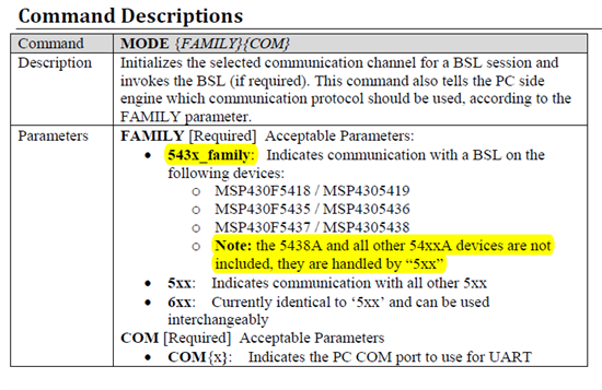
    Looking at the BSL_Scripter_Usage_Guide.pdf that comes in the www.ti.com/lit/pdf/slau319 download in the BSL Scripter folder, see page 1 under the description for the MODE command:

    So you should not be using the command "MODE 543x_family USB" because you are using the F5419A (the 543x_family is only used for a non-A device, which has some different BSL version in it). Instead, you should use 5xx instead of 543x_family.

    Further, you should use COM3 (or whatever number COM port used) not USB. USB is indicating that you are using a device with a USB BSL like f5529, not UART BSL like your F5419A.

    So the command you should use is MODE 5xx COM3. (Modify COM# to match what's in device manager).

    Hope this helps get you up and running!

    Regards,

    Katie


**Attention** This is a public forum