This thread has been locked.

If you have a related question, please click the "Ask a related question" button in the top right corner. The newly created question will be automatically linked to this question.

MSP430 Launchpad Baud Rate: Understanding UCA0BR0, UCA0BR1 and UCA0MCTL

Other Parts Discussed in Thread: MSP430G2553

Hi all,

I am currently trying to use the MSP430G2553 (Launchpad) to send data to the PC using UART. Using the example code provided (below), I was able to do this with a clock of 1MHz. However, I am trying to use a clock of 16MHz and I am not sure what to do, I know how UCA0BR0 is calculated, but 16000000/9600 = 1667 which causes truncation in UCA0BR0.

Can someone explain to me how to get the 9600 Baud Rate with a 16MHz clock instead of a 1MHz clock? Is the UCA0BR1 value for when UCA0BR0 overflows? Also how does UCA0MCTL work, as I cannot find any useful help with setting that value in software from the user guides. Are there any other variables that I would need to set for using this 16MHz clock?

void main(void)

{
WDTCTL = WDTPW + WDTHOLD; // Stop WDT
BCSCTL1 = CALBC1_1MHZ; // Set DCO
DCOCTL = CALDCO_1MHZ;
P1SEL = BIT1 + BIT2 ; // P1.1 = RXD, P1.2=TXD
P1SEL2 = BIT1 + BIT2 ; // P1.1 = RXD, P1.2=TXD
UCA0CTL1 |= UCSSEL_2; // SMCLK
UCA0BR0 = 104; // 1MHz 9600
UCA0BR1 = 0; // 1MHz 9600
UCA0MCTL = UCBRS0; // Modulation UCBRSx = 1
UCA0CTL1 &= ~UCSWRST; // **Initialize USCI state machine**
IE2 |= UCA0RXIE; // Enable USCI_A0 RX interrupt

__bis_SR_register(LPM0_bits + GIE); // Enter LPM0, interrupts enabled
}

// Echo back RXed character, confirm TX buffer is ready first
#pragma vector=USCIAB0RX_VECTOR
__interrupt void USCI0RX_ISR(void)
{
while (!(IFG2&UCA0TXIFG)); // USCI_A0 TX buffer ready?
UCA0TXBUF = 'z';
}

Thanks,

Matt

  • Yes, UCA0BR1 is the "overflow" of UCA0BR0. Hence 1667 is split into UCA0BR1 = 6; and UCA0BR0 = 131;

    (6*256 + 131) = (1536 + 131) = 1667

    This and the details of UCA0MCTL are described in the User's Guide slau144i.pdf Chapter 15

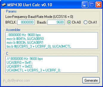
  • Here is tool that you can use for calculation...

    http://forum.43oh.com/topic/2640-uart-configurator

  • Hi,

         Can you please elaborate how exactly are you splitting and coming to the conclusion that we have to feed the values 131 and 6 respectively.  general calculation would be 8M/9600= 833. So how exactly are we splitting it with UCABR1 and UCABRO register?? 

  • Deepak kalalbandi said:

    Hi,

         Can you please elaborate how exactly are you splitting and coming to the conclusion that we have to feed the values 131 and 6 respectively.  general calculation would be 8M/9600= 833. So how exactly are we splitting it with UCABR1 and UCABRO register?? 

    For 9600 bps at 8 MHz...
    8000000 / 9600 = 833.333
    833 dec = 0341 hex
    UCABR0 = 41 hex = 65 dec
    UCABR1 = 3
  • Deepak kalalbandi said:
    So how exactly are we splitting it with UCABR1 and UCABRO register?? 

    UCABR0 and UCABR1 are low and high byte of a 16 bit value.

    If the value is decimal 833, its hexadecimal value would be 0x0314, so 0x14 goes to UCBR0 and 0x03 goes to UCBR1.

    For the remainder of 0.333, there is MCTL. It adds a pattern to UCBR(0/1) that makes the divider by 1 larger for some of the bits. Details and a formula are found in the users guide.
    Basically, if the first bit is too short (833 instead of 833.333 clock pulses) and the second is too short too, then the third has to be made longer (834 clock pulses) to keep the average baudrate. MCTL controls which bits have to be made longer by one clock cycle.

  • Thanks a lot Michael, i was worried about the remainder calculation. 

  • You can even type cast the whole value directly and separate LSB and MSB and place it in the corresponding registers. 

  • Hi Matt,

    I'm a little confused about the relationship between baud rate and bit per second. Does 2400 baud rate means 2400bps for msp430 microcontrollers? Or assuming that my uart mode is set as 8-bit data and 2 stop bits, for this case, 2400 baud rate means 2400bps or 2400*10=24000bps?

    Thanks!

    Wang

  • user4215514 said:
    I'm a little confused about the relationship between baud rate and bit per second.

    You are not alone. They mean the same thing if the symbols used carry only one bit of information. Thus most people use these two terms interchangeably and unknowingly.

  • Baud is related to gross bit rate expressed as bits per second.
    So it's not bytes/sec and as a uart byte uses 10bits only 240 chars per seconds shows up at the other end.
  • Dear freinds

    I am working on sending infinite series of bytes from the MSP430G2553 to the PC and sniff the serial port (COM) via putty, using the code below.
    However, I did get anything on the putty monitor given that I am not getting any error message when running the code.

    Would please check this piece of code (do I need to clear the TX flag?)?

    Thank you

    #include "msp430g2553.h" void main(void) { WDTCTL = WDTPW + WDTHOLD; // Stop the Watch dog //------------------- Configure the Clocks -------------------// if (CALBC1_1MHZ==0xFF) // If calibration constant erased { while(1); // do not load, trap CPU!! } DCOCTL = 0; // Select lowest DCOx and MODx settings BCSCTL1 = CALBC1_1MHZ; // Set range DCOCTL = CALDCO_1MHZ; // Set DCO step + modulation //--------- Setting the UART function for P1.1 & P1.2 --------// P1SEL |= BIT1 + BIT2; // P1.1 UCA0RXD input P1SEL2 |= BIT1 + BIT2; // P1.2 UCA0TXD output //------------ Configuring the UART(USCI_A0) ----------------// UCA0CTL1 |= UCSSEL_2 + UCSWRST; // USCI Clock = SMCLK,USCI_A0 disabled UCA0BR0 = 104; // 104 From datasheet table- UCA0BR1 = 0; // -selects baudrate =9600,clk = SMCLK UCA0MCTL = UCBRS_1; // Modulation value = 1 from datasheet UCA0STAT |= UCLISTEN; // loop back mode enabled UCA0CTL1 &= ~UCSWRST; // Clear UCSWRST to enable USCI_A0 while(1) { UCA0TXBUF = 'A'; // Transmit a byte } }
  • Hi Murtadha!

    You have to wait before the buffer is free again before writing the next byte to it. Add

    while( !(IFG2 & UCA0TXIFG) );

    before copying 'A' to the TX buffer. And it is recommended to first set UCSWRST alone, then configure everything and finally clear the bit.

    Dennis

  • Hi, Dennis

    Thank you for your support
    It is working fine

    Regards
    Murtadha
  • Hi, Dennis

    Coming back to what you suggested about setting the UCSWRST first, you mean it is recommended to do it like this:


    UCA0CTL1 |= UCSWRST; UCA0CTL1 |= UCSSEL_2; UCA0BR0 = 104; UCA0BR1 = 0; UCA0MCTL = UCBRS_1; UCA0STAT |= UCLISTEN; UCA0CTL1 &= ~UCSWRST;

    Thanks,

    Murtadha
  • Hello guys

    Two questions:

    - I am sending data of 4 byte out through the UART of MSP430G2553, and checking these bytes(bit stream) via and oscilloscope (through port 1.2)
    With the settings shown bellow (12 MHz, 115200 bps) what should be the time required for send these 4 bytes(32 bits + 4 stop bits + 4 space bits= 40 bits)?
    Is it 8.6 Micro Sec./bit?

    - What does it mean that the loop back mode to be enabled? is for echo back?
    UCA0STAT |= UCLISTEN; // loop back mode enabled

    Thank you
    Murtadha


    #include "msp430g2553.h" unsigned int i; void main(void) { WDTCTL = WDTPW + WDTHOLD; // Stop the Watch dog //------------------- Configure the Clocks -------------------// if (CALBC1_12MHZ==0xFF) // If calibration constant erased { while(1); // do not load, trap CPU!! } DCOCTL = 0; // Select lowest DCOx and MODx settings BCSCTL1 = CALBC1_12MHZ; // Set range DCOCTL = CALDCO_12MHZ; // Set DCO step + modulation //--------- Setting the UART function for P1.1 & P1.2 --------// P1SEL |= BIT1 + BIT2; // P1.1 UCA0RXD input P1SEL2 |= BIT1 + BIT2; // P1.2 UCA0TXD output //------------ Configuring the UART(USCI_A0) ----------------// UCA0CTL1 |= UCSSEL_2 + UCSWRST; // USCI Clock = SMCLK,USCI_A0 disabled UCA0BR0 = 104; // 104 From datasheet UCA0BR1 = 1; // baudrate =115200,clk = SMCLK UCA0MCTL = UCBRS_1; // Modulation value = 1 from datasheet UCA0STAT |= UCLISTEN; // loop back mode enabled UCA0CTL1 &= ~UCSWRST; // Clear UCSWRST to enable USCI_A0 while(1) { for (i = 0; i < 1000; i++); while( !(IFG2 & UCA0TXIFG) ); UCA0TXBUF = 0xAA; // Transmit a byte while( !(IFG2 & UCA0TXIFG) ); UCA0TXBUF = 0x01; // Transmit 2nd Byte while( !(IFG2 & UCA0TXIFG) ); // Transmit 3rd byte UCA0TXBUF = 0x00; while( !(IFG2 & UCA0TXIFG) ); // Transmit 4th Byte UCA0TXBUF = 0x08; } }

  • Yes. Settign SWRST resets the USCI's internal state machine to a safe point. If you don't, any change to the configuration can cause the stat emachine run havoc and sdo unexpected things. However, after a device reset, SWRST will always be set. But if your code is modular, it cannot assuem that it is only called directly after a reset.
  • "Is it 8.6 Micro Sec./bit?"

    If the baudrat eis set to 115200Bd, each bit should last 1s/115200. That's the definition of baudrate. However, you seldom get an exact 115200 bit clock, as it would require the base clock being an integral multiple of it. The important thing is that any clock error doesn't accumulate to more than 1/2 bit length during one byte (the UART protocol re-synchronizes with the next start bit anyway). THis means 5% maximum error for both, sender and receiver. So you shouldn't be more than 2.5% off.
    This is where the modulation kicks in. Based on the modulation patern, for some bits the USCI is using a by 1 larger clock divider, making the bit a bit shorter than the others, to compensate for those being too long. (by the mising fractional part of the ideal clock divider).

    "What does it mean that the loop back mode to be enabled? is for echo back?UCA0STAT |= UCLISTEN; // loop back mode enabled"

    Loopback mode feeds the USCI TX output back into the RX input. It's something like an internal echo function if you don't have a real counterpart. Wiht one difference: on a real echo, the echoed byte woudl start when the sent byte has been completely transmitted and received. With the UCLISTEN loopback bit set, the echo will come in simultaneously with the data being sent. So you have a different sequence of events.

    Als be aware that your for loop doesn't necessarily wait. Depending on optimization level, teh compiler can detect that the loop does nothign than incrementing i and leaving wit with the value 1000 at the end, so the generated code may simply set i to 1000 without counting. Or, since i isn't used later, it might be discarded completely.
    For delays, eithe ruse a timer or use the __delay_cycles(x) intrinsic, which will always 'waste' the given (as compile-time constant!) number of x CPU cycles.
  • #include "msp430g2553.h"
    unsigned int i;
    void main(void)
    {
      WDTCTL = WDTPW + WDTHOLD; // Stop the Watch dog
    
      //------------------- Configure the Clocks -------------------//
    
      if (CALBC1_12MHZ==0xFF)   // If calibration constant erased
         {
            while(1);          // do not load, trap CPU!!
         }
    
       DCOCTL  = 0;             // Select lowest DCOx and MODx settings
       BCSCTL1 = CALBC1_12MHZ;   // Set range
       DCOCTL  = CALDCO_12MHZ;   // Set DCO step + modulation
    
      //--------- Setting the UART function for P1.1 & P1.2 --------//
    
       P1SEL  |=  BIT1 + BIT2;  // P1.1 UCA0RXD input
       P1SEL2 |=  BIT1 + BIT2;  // P1.2 UCA0TXD output
    
      //------------ Configuring the UART(USCI_A0) ----------------//
    
       UCA0CTL1 |= UCSWRST;                      // **Put state machine in reset**
       UCA0CTL1 |= UCSSEL_3;                     // CLK = SMCLK
    
       // 115200 BAUD, CLK=12MHz
       		  UCA0BR0 = 6; //this is working
       		  UCA0BR1 = 0; //this is working
       		  // UCBRF = 8, UCBRS = 0, UCOS16 = 1
       		  // BITS| 7 6 5 4 | 3 2 1  |   0    |
       		  // UCAxMCTL = | UCBRFx  | UCBRSx | UCOS16 |
       		  UCA0MCTL = 0x81; //this works fine
    
       UCA0CTL1 &= ~UCSWRST;             // Clear UCSWRST to enable USCI_A0
    
    while(1)
    {
    	for (i = 0; i < 1000; i++);
    
    	while( !(IFG2 & UCA0TXIFG) );


    	UCA0TXBUF = 0xAA;                  // Transmit a byte
    
    	while( !(IFG2 & UCA0TXIFG) );
    	UCA0TXBUF = 0x01;
    
    	while( !(IFG2 & UCA0TXIFG) );
    	UCA0TXBUF = 0x00;
    
    	while( !(IFG2 & UCA0TXIFG) );
    	UCA0TXBUF = 0x08;
    
    }
    }

    Thank you Mr. Gross,

    Actually I set the registers again as I was mistaken, please the code above. With these settings the time for 1 bit is around 8.3 Micro Sec.
    Regarding the for i, I will use delay cycles instead, thank you for suggestions

    Kind regards

    Murtadha

**Attention** This is a public forum