This thread has been locked.

If you have a related question, please click the "Ask a related question" button in the top right corner. The newly created question will be automatically linked to this question.

MSP430F5529 Internal Temperature reading

Other Parts Discussed in Thread: MSP430F5529

Hi,

I am having trouble with MSP430F55xx_adc_10 example code that reads internal temperature sensor.

The degree C reading is -112.952.

Is there a setting in the compiler or linker I need to set?  Looking carefully at the values I noticed that the Code Composer V5.4 results in a positive number "(CALADC12_15V_85C - CALADC12_15V_30C)", where

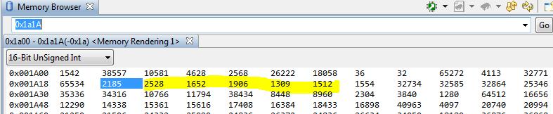
CALADC12_15V_85C is 2468 decimal

CALADC12_15V_30C is 49674 decimal

    temperatureDegC = (float)(((long)temp - CALADC12_15V_30C) * (85 - 30)) /
            (CALADC12_15V_85C - CALADC12_15V_30C) + 30.0f;

I suspect that this is why the example code temperatureDegC value (in degree C) is a negative number.

Thanks,

Ed

  • I'm a bit puzzled...

    You're using the wrong calibration values.

    First, if the code is xxx_adc_10 example code, how come you usee CALADC12 calibration values? ADC10 and ADC12 are quite different. Not only regarding the resolution.

    Then, the calibration values are actual readings of the ADC output at a given temperature. So for an ADC12, the values must be in the range of 0..4095, and for an ADC10 in the range of 0..1023. 49674 definitely isn't a valid reading. Also, since the sensor has a constant positive temperature coefficient, the calibration value  for 85°C must be higher than the value for 30°C.

    (CALADC12_15V_85C - CALADC12_15V_30C) gives the difference between 85°C and 30°C in ADC counts. Dividing it by 55 (85-30) gives the number of ADC counts per °C. If you subtract the (known) rvalue for 30°C from the ADC result, and divide the rest by this tick count, you'll get the temperature difference relative to 30°C. Adding 30 gives the temperature relative to 0°C.

  • Is this code not working?

    //******************************************************************************
    //  MSP430F552x Demo - ADC12, Sample A10 Temp and Convert to oC and oF
    //
    //  Description: A single sample is made on A10 with reference to internal
    //  1.5V Vref. Software sets ADC12SC to start sample and conversion - ADC12SC
    //  automatically cleared at EOC. ADC12 internal oscillator times sample
    //  and conversion. In Mainloop MSP430 waits in LPM4 to save power until
    //  ADC10 conversion complete, ADC12_ISR will force exit from any LPMx in
    //  Mainloop on reti.
    //  ACLK = n/a, MCLK = SMCLK = default DCO ~ 1.045MHz, ADC12CLK = ADC12OSC
    //
    //  Uncalibrated temperature measured from device to devive will vary do to
    //  slope and offset variance from device to device - please see datasheet.
    //
    //  NOTE:1.REFMSTR bit in REFCTL0 regsiter is reset to allow the ADC12_A reference
    //    control regsiters handle the reference setting. Upon resetting the REFMSTR
    //    bit, all the settings in REFCTL are 'dont care' and the legacy ADC12
    //    control bits (ADC12REFON, ADC12REF2_5, ADC12TCOFF and ADC12REFOUT) control
    //    the reference system.
    //    2. Use the TLV calibrated temperature to measure temperature
    //   (the TLV CALIBRATED DATA IS STORED IN THE INFORMATION SEGMENT, SEE DEVICE DATASHEET)
    //
    //                MSP430F552x
    //             -----------------
    //         /|\|              XIN|-
    //          | |                 |
    //          --|RST          XOUT|-
    //            |                 |
    //            |A10              |
    //
    //   F. Chen
    //   Texas Instruments Inc.
    //   Dec. 2012
    //   Built with IAR Embedded Workbench Version: 5.51.1 & Code Composer Studio V5.2.1
    //******************************************************************************
    
    #include <msp430.h>
    
    #define CALADC12_15V_30C  *((unsigned int *)0x1A1A)   // Temperature Sensor Calibration-30 C
                                                          //See device datasheet for TLV table memory mapping
    #define CALADC12_15V_85C  *((unsigned int *)0x1A1C)   // Temperature Sensor Calibration-85 C
    
    unsigned int temp;
    volatile float temperatureDegC;
    volatile float temperatureDegF;
    
    int main(void)
    {
      WDTCTL = WDTPW + WDTHOLD;                 // Stop WDT
      REFCTL0 &= ~REFMSTR;                      // Reset REFMSTR to hand over control to
                                                // ADC12_A ref control registers
      ADC12CTL0 = ADC12SHT0_8 + ADC12REFON + ADC12ON;
                                                // Internal ref = 1.5V
      ADC12CTL1 = ADC12SHP;                     // enable sample timer
      ADC12MCTL0 = ADC12SREF_1 + ADC12INCH_10;  // ADC i/p ch A10 = temp sense i/p
      ADC12IE = 0x001;                          // ADC_IFG upon conv result-ADCMEMO
      __delay_cycles(100);                       // delay to allow Ref to settle
      ADC12CTL0 |= ADC12ENC;
    
      while(1)
      {
        ADC12CTL0 &= ~ADC12SC; 
        ADC12CTL0 |= ADC12SC;                   // Sampling and conversion start
    
        __bis_SR_register(LPM4_bits + GIE);     // LPM0 with interrupts enabled
        __no_operation();
    
        // Temperature in Celsius. See the Device Descriptor Table section in the
        // System Resets, Interrupts, and Operating Modes, System Control Module
        // chapter in the device user's guide for background information on the
        // used formula.
        temperatureDegC = (float)(((long)temp - CALADC12_15V_30C) * (85 - 30)) /
                (CALADC12_15V_85C - CALADC12_15V_30C) + 30.0f;
    
        // Temperature in Fahrenheit Tf = (9/5)*Tc + 32
        temperatureDegF = temperatureDegC * 9.0f / 5.0f + 32.0f;
    	 
        __no_operation();                       // SET BREAKPOINT HERE
      }
    }
    
    #pragma vector=ADC12_VECTOR
    __interrupt void ADC12ISR (void)
    {
      switch(__even_in_range(ADC12IV,34))
      {
      case  0: break;                           // Vector  0:  No interrupt
      case  2: break;                           // Vector  2:  ADC overflow
      case  4: break;                           // Vector  4:  ADC timing overflow
      case  6:                                  // Vector  6:  ADC12IFG0
        temp = ADC12MEM0;                       // Move results, IFG is cleared
        __bic_SR_register_on_exit(LPM4_bits);   // Exit active CPU
        break;
      case  8: break;                           // Vector  8:  ADC12IFG1
      case 10: break;                           // Vector 10:  ADC12IFG2
      case 12: break;                           // Vector 12:  ADC12IFG3
      case 14: break;                           // Vector 14:  ADC12IFG4
      case 16: break;                           // Vector 16:  ADC12IFG5
      case 18: break;                           // Vector 18:  ADC12IFG6
      case 20: break;                           // Vector 20:  ADC12IFG7
      case 22: break;                           // Vector 22:  ADC12IFG8
      case 24: break;                           // Vector 24:  ADC12IFG9
      case 26: break;                           // Vector 26:  ADC12IFG10
      case 28: break;                           // Vector 28:  ADC12IFG11
      case 30: break;                           // Vector 30:  ADC12IFG12
      case 32: break;                           // Vector 32:  ADC12IFG13
      case 34: break;                           // Vector 34:  ADC12IFG14
      default: break;
      }
    }
    
  • Hi,

    Yes this is the same example code.  I built this code to run on EXP-MSP430F5529 development board.  i did not change anything.  Your help is appreciated.

    Ed

  • Ed,

    This should work. I recommend checking other MSP430F5529 device.

    Regards,
    Maciej 

  • Jens-Michael Gross said:
    if the code is xxx_adc_10 example code, how come you usee CALADC12 calibration values?

    Ah, adc_10 stands for ADC channel 10 demo, not for ADC10 module demo. :)

    Nevertheless, the code indeed should work. I fit doesn't, then the calibration values are wrong.

    Try the following:

    Change the reference to 2.5V

    ADC12CTL0 = ADC12SHT0_8 | ADC12REFON | ADC12ON | ADC12REF2_5V;

    and use the 2.5V calibration values (change the addresses to 0x1A22 and 0x1A24). Same rules apply.: Both values must be between 0 and 4095, and the second (85°C) must be higher than the first (30°C).
    You can also check in memory view in the debugger.

  • Hi,

    I dumped the 1.5v, 2.0v and 2.5v Calibrated data values from MSP430F5529 address:

                                                                                     Address  // value(decimal)

      caladc12_15v_30c_val =  *((unsigned int *)0x1A1a);   // 49674
      caladc12_15v_85c_val =  *((unsigned int *)0x1A1c);   // 2468

      caladc12_20v_30c_val =  *((unsigned int *)0x1A1e);   // 49546
      caladc12_20v_85c_val =  *((unsigned int *)0x1A20);   // 1862
      caladc12_25v_30c_val =  *((unsigned int *)0x1A22);   // 49465
      caladc12_25v_85c_val =  *((unsigned int *)0x1A24);   // 1477

    This looks incorrect, bigger value should be found at the 85C and lower value at 30C.  You can see going from 2.0V to 2.5V the values decrease which makes sense since the voltage reference is going up.  So the odd thing here is the 30C value is greater than the 85C value.

    Can you read your MSP430F5529 Calibration data and verify the results?

    Thanks,

    Ed

  • Ed Lombardo said:
    Can you read your MSP430F5529 Calibration data and verify the results?

    Sorry, don't have one (actually no MSP at all in reach where I could read them), but it looks liek the 30° values are crap.

    It seesm that teh values have been shifted down by 2 bit. If you multiply them with 4 (16 bit multiplication, so the upper two bits are discarded), then you get 2088, 1576 and 1252. Which looks good. However, the two LSBs are msising in the value, even if this analysis should be correct.

  • Hi Ed,

    Try casting these pointers to unsigned short, instead of unsigned int, and let me know if that helps to resolve this problem.   If the output format of your project is set to EABI (as opposed to legacy COFF), then the size of the int data type is 4 bytes.


    Best,

        Rick

  • Rick Nardone said:
    If the output format of your project is set to EABI (as opposed to legacy COFF), then the size of the int data type is 4 bytes.

    Really? Hmmm, this will surely break a lot of existing code, including almost all TI code examples published before. Nobody ever used 'short'
    I also miss the 'long long' datatype in this table.

    However, the values he posted are within 16 bit range. Even if the display has been truncated to 16 bit form a 32 bit read, the (truncated) values are still wrong. And only the ones for 30°C, while a wrong data format would show wrong values for the 85°C values too, as they are read from contiguous memory.

  • Hi,

    I suggest using the memory viewer to look at the calibration data.

    Here is what I have from a F5529:


     The data type problem is a long shot, but it is an easy test implement and run quickly.   Looking at this data with the debugger is a better way to show what is really in memory.   

     Best,

          Rick


    @JMG: I truncated the table, and long long is still a valid data type as shown in the MSP430 Compiler v4.1 User's Guide. 


  • Hi,

    This may be an errata ADC29:


        Best,

               Rick


    slaz314h.pdf
  • Hi Rick,

    My symptoms in this TI MSP430 Eval board matches wha this errata says.  How can I read the silicon revision of this device.  Can I program the calibration data to be correct?

    Thanks,

    Ed

  • Ed Lombardo said:
    How can I read the silicon revision of this device

    See the attached errata document, page 3 for this information.


    You can recalibrate this device, and I would recommend storing the new calibration values in a section of the Information Memory (like Info A).


    Best,

        Rick

    slaz314h.pdf
  • Hi Ed,

    One addtional note as a follow up.  The  Device Descriptor Table (DDT) that contains the calibration values is READ ONLY.  It cannot be erased or written.  If you decide to do a recalibration, you will need to store the updated values in flash memory.  The information segments of flash memory, are a good location for this type of data.


    Best,

        Rick

  • Hi Rick,

    I am trying the above code for reading the internal temperature of msp430f5529, also to keep checkpoints i am trying to keep an LED at the output so, if the internal temperature is below a value (say 10 degC ) the LED should glow, but when I try to do this the LED is always ON, can you please help with me for how to implement the same.

    Also how does the memory browser show the values as when i try to enter the register name it is not showing any values.

**Attention** This is a public forum