This thread has been locked.

If you have a related question, please click the "Ask a related question" button in the top right corner. The newly created question will be automatically linked to this question.

Timer not generating interrupt at desired time...it is varying

Other Parts Discussed in Thread: MSP430G2231

Hi Sir,

I am using MSP430g2231 microcontroller to generate a clock frequency of 38kHz in one of the GPIO pin(P1.4).

That means I am trying to generate a clock cycle pulses of period "26micro seconds"(1/38khz). I have used the

configurations and written the code as shown below. The problem that I am facing is, when I am trying to check

the result in oscilloscope the cycle period varies in between 32, 34 and 38 micro seconds. So my question is

what am I doing wrong with my code? Is there any wrong with my clock selection..since I am using calibrated

clock (internal) values of 1Mhz or I am doing wrong in setting values of  TimerA CCR0 value? Please provide the 

support and help.  Thanks.

#include "msp430g2231.h"

void main(void) {
WDTCTL = WDTPW + WDTHOLD; // Stop watchdog timer

if (CALBC1_1MHZ ==0xFF || CALDCO_1MHZ == 0xFF)
{
while(1); // If calibration constants erased
// do not load, trap CPU!!
}

DCOCTL=CALDCO_1MHZ;
BCSCTL1 =CALBC1_1MHZ;

//make Port pin 4 as output*/
P1DIR = BIT4;
P1OUT = 0x00;

configureTimer();
__enable_interrupt();
while(1);
}
/*I am trying to generate each pulse duration 13us*/
void configureTimer()
{
CCR0 = 13-1; // set up terminal count
TA0CTL = TASSEL_2 + ID_0 + MC_1; // SMCLK + SMCLK/1 +up mode

// enable interrupts
CCTL0 = CCIE; // enable timer interrupts
}

//Toggling the pin 1.4
#pragma vector = TIMERA0_VECTOR
__interrupt void Timer_A0_clkgen(void)
{
TA0CCTL0 &= ~CCIFG;
P1OUT ^= BIT4;
}

  • It could be interrupt latency variation. Try 8MHz for MCLK and SMCLK, feed timer with SMCLK/8 and see if it helps.

    If you want perfect timing then better consider timer PWM output mode.

  • Sir,

    How will I select 8Mhz since in the header file its not mentioned.

    The header file has the following information only:(only for 1Mhz)

    #ifndef __DisableCalData

    SFR_8BIT(CALDCO_1MHZ); /* DCOCTL Calibration Data for 1MHz */
    SFR_8BIT(CALBC1_1MHZ); /* BCSCTL1 Calibration Data for 1MHz */

    #endif /* #ifndef __DisableCalData */

  • Indranil said:
    How will I select 8Mhz since in the header file its not mentioned.

    Oh, you are not using g2553. Then try to run timer at 1MHz/8 clock and then check variation. Supposedly it shall be much smaller. As I said - better consider PWM. Even embedded software is not that deterministic if we talk about timing - especially when you try to count every CPU cycle.

  • Ok I will check it using PWM output mode..and let you know the results.

    One thing I want to know -can I connect external clock of 16Mhz for Msp430g2231 device? 

    Thanks.

  • You could have used one of the Timer output pins to generate a more precise clock. Unfortunately P1.4 is not one of them. Could you use P1.1, P1.2, P1.5, P1.6, or P2.6 instead?

  • I have tried using other pins, but it shows same behaviour.

    I have done several testing to create time interrupt in the range of 18 microseconds to 5 microseconds by

    reducing the CCR0 value. But what I have noticed is it is unable to create timer interrupt for small period. Minimum

    is more than 20us. Why is that ? Is it because of interrupt latency ? My application needs to generate pulses of

    26microseconds duration. Do I need to use high clock source (more than 1 Mhz). I am trying to use external

    crystal oscillator clock(16Mhz) to get more accurate timing. But the problem is I am getting oscialltion fault while initializing the clock. Can anybody provide me some help to guide how to initialize 16Mhz external clock for Msp430g2231 device?.  

  • Even I have tried to use PWM module to generate a duration 26us duration.(it can be any duty cycle). The output what I have noticed is that pulses are varying. Some pulse will come with 26us duration but some pulse will not . If I try the same for 1milliseconds it is somewhat better. But my application requires 26us. I am out of ideas why my device(MSP430g2231) is not supporting less delays. Please help. 

  • #include "msp430g2231.h"

    void main(void) {
    WDTCTL = WDTPW + WDTHOLD; // Stop watchdog timer

    if (CALBC1_1MHZ == 0xFF || CALDCO_1MHZ == 0xFF)
    {
    while(1); // If calibration constants erased
    // do not load, trap CPU!!
    }

    DCOCTL = (CALDCO_1MHZ + 0x20) & 0xE0;
    BCSCTL1 = CALBC1_1MHZ;

    //make Port pin P1.1 as Timer output
    P1SEL = BIT1;
    P1DIR = BIT1;

    TACCR0 = 14-1;
    TACCTL0 = OUTMOD_4;
    TACTL = TASSEL_2 | MC_1;

    while(1);
    }

  • Thanks for the reply and the sample code..:)

    What have you done in the following line ? I didn't understand

    DCOCTL = (CALDCO_1MHZ + 0x20) & 0xE0;

  • 38kHz*26 = 988kHz; 38kHz*28 = 1064kHz; I took a blind shoot aimed at making the DCO to oscillate closer to 1.064MHz and without modulation. Was I close?

    You can actually adjust the setting of DCOCTL to make the frquency at P1.1 even closer to 38kHz.

  • Indranil said:
    I am trying to generate a clock cycle pulses of period "26micro seconds"(1/38khz). [..] in oscilloscope the cycle period varies in between 32, 34 and 38 micro seconds.

    If the MSP runs on 1MHz, this means 1 MCLK cycle is 1µs.

    An ISR can only be executed when the current instruction is finished. Which may take 1 to 6 MCLK cycles = 1-6µs. This is one reason for timing jitter.

    Another thing is that you only have 13µs between two interrupts. But entering an ISR takes time, returning from it takes time, and executing the code inside the ISR takes time. ~20µs total.

    Since you're using CCR0 for the interrupt, you don't need to clear CCIFG in CCTL0. It is automatically done when the ISR is entered (only for CCR0!). It saves you a few clock cycles. Still calling and executing your ISR takes more cycles than you have between two interrupts. Even without the mentioned jitter.

    So what you're trying to do is simply not possible when you run the CPU with its default 1MHz.

  • Jens-Michael Gross said:

    I am trying to generate a clock cycle pulses of period "26micro seconds"(1/38khz). [..] in oscilloscope the cycle period varies in between 32, 34 and 38 micro seconds.

    If the MSP runs on 1MHz, this means 1 MCLK cycle is 1µs.

    Since you're using CCR0 for the interrupt, you don't need to clear CCIE in CCTL0. It is automatically done when the ISR is entered (only for CCR0!). [/quote]

    Do you mean CCIFG?

    Even though there are no calibration constants for 4, 8, 16 MHz for the msp430g2231, would there be any reason he couldn't run it at 16 MHz and determine the calibration constants himself?

  • Joseph Raslavsky said:
    Even though there are no calibration constants for 4, 8, 16 MHz for the msp430g2231, would there be any reason he couldn't run it at 16 MHz and determine the calibration constants himself?

    Yes he can. By using TI sample code, msp430g2xx1_dco_flashcal.c

  • Thanks Michael for clearing my doubt. :) Moreover you said that we can calibrate the controller for high clock(16Mhz).

    If such is the case I will try with that, So is this the only solution/workaround for my problem?

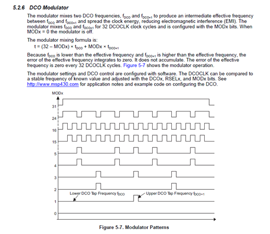
  • I think I understand what the modulation is doing (during every 32 DCO clocks some are fdco and some are fdco+1). But all you are doing is swapping out 1 cycle of slightly larger period and replacing it with 1 cycle of slightly smaller period, succeeding in changing only the phase of 1 cycle, and still ending up with 32 cycles that take the same time. If modx = 2, for example, it's still 1 cycle fdco exchanged for one cycle fdco+1 twice each 32 cycles. Unless of course if fdco+1 is twice the frequency of fdco, then you would be exchanging two cycles of fdco+1 for each fdco cycle. But that doesn't appear to be the case.

  • Joseph Raslavsky said:

    I think I understand what the modulation is doing (during every 32 DCO clocks some are fdco and some are fdco+1). ...

    Correct.

    Joseph Raslavsky said:

    ... But all you are doing is swapping out 1 cycle of slightly larger period and replacing it with 1 cycle of slightly smaller period, succeeding in changing only the phase of 1 cycle, and still ending up with 32 cycles that take the same time. ...

    Do you mean OCY did that? OCY did not do that at all. What he did with the setting of DCOCTL is not important at all. The important thing is not using interrupt to toggle the port pin and use a Timer Output pin instead.

  • old_cow_yellow said:

    Do you mean OCY did that? OCY did not do that at all. What he did with the setting of DCOCTL is not important at all. The important thing is not using interrupt to toggle the port pin and use a Timer Output pin instead.

    No. Not at all. I'm trying to understand how this modulation works (obviously it does), but I don't see how.

  • Joseph Raslavsky said:

    Do you mean OCY did that? OCY did not do that at all. What he did with the setting of DCOCTL is not important at all. The important thing is not using interrupt to toggle the port pin and use a Timer Output pin instead.

    No. Not at all. I'm trying to understand how this modulation works (obviously it does), but I don't see how.

    [/quote]

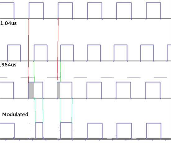
    Okay. The guys that designed the DCO hardware are not going to answer your question. But I think what they did can be illustrated by an example below.

    Let us assume that fdco has a period of 1.040 usec and fdco+1 has a period of 0.960 usec. When we (the users) set modx = 2, the DCO hardware will generate a DCOCLK signal with a waveform that resembles a clock with a period of 1.035 usec. But if we examing DCOCLK in details, it repeats itself evey 32 cycles. Of which, (32-2) cycles have periods of 1.040 usec, and the other 2 cycles have priodes of 0.960 usec. And (1.040 * (32-2) + 0.0960 * 2)/32 = 1.035 usec

  • Indranil said:
    is this the only solution/workaround for my problem?

    If the CPU requires a certain number of cycles for a job and it has only a certain number of cycles per second it can do the job only a certain number of times per second. If you want it more often, reduce the number of cycles used (which you can't) or increase the number of cycles per second (by increasing CPU speed). Or reduce your expectations (live with less jobs per second)

    Simple math, no magic.

  • old_cow_yellow said:


    Let us assume that fdco has a period of 1.040 usec and fdco+1 has a period of 0.960 usec. When we (the users) set modx = 2, the DCO hardware will generate a DCOCLK signal with a waveform that resembles a clock with a period of 1.035 usec. But if we examing DCOCLK in details, it repeats itself evey 32 cycles. Of which, (32-2) cycles have periods of 1.040 usec, and the other 2 cycles have priodes of 0.960 usec. And (1.040 * (32-2) + 0.0960 * 2)/32 = 1.035 usec

    But somehow you have to increase the number of transitions so that the timer for example counts at the average frequency. So I don't think the MSP430 is just swapping different frequencies. At least graphically it seems only the phase changes.

  • fdco and fdco+1 are not two different continuous clocks. They are two different settings of the same oscillator. This oscillator can switch between these two frequencies in a cycle by cycle bases and always start each cycle at a phase angle at 0 degrees.

  • old_cow_yellow said:

    fdco and fdco+1 are not two different continuous clocks. They are two different settings of the same oscillator. This oscillator can switch between these two frequencies in a cycle by cycle bases and always start each cycle at a phase angle at 0 degrees.

    Yes, I see. Thanks. Maybe can be simply accomplished by a triac (which IIRC will stay on for the duration of a single pulse once fired) in some capacitive feedback path controlled by the modulator.

  • Joseph Raslavsky said:
    Do you mean CCIFG?

    Yes. Changed it.Thanks.

    Joseph Raslavsky said:
    I think I understand what the modulation is doing

    Yes, you seem to. But apparently you did not understand how the DCO is working.

    The DCO is not a multi-frequency generator. It is an R/C oscillator where R and C can be switched digitally. R is switched by the RSEL value. C is switched by DCOx.

    So by switching from DCOx to DCOx+1, this changes the capacitance of the R/C oscillator and therefore the time constant of the oscillation. It doesn't switch to another frequency, it changes the oscillation frequency itself.

    So no phase shift between two frequencies, but a chage of the wavelength due to a change of the capacitance. Done at the zero crossing point.

  • Jens-Michael Gross said:

    The DCO is not a multi-frequency generator. It is an R/C oscillator where R and C can be switched digitally. R is switched by the RSEL value. C is switched by DCOx.

    So by switching from DCOx to DCOx+1, this changes the capacitance of the R/C oscillator and therefore the time constant of the oscillation. It doesn't switch to another frequency, it changes the oscillation frequency itself.

    So no phase shift between two frequencies, but a chage of the wavelength due to a change of the capacitance. Done at the zero crossing point.

    Thanks. That also makes clear the meaning of the DCOx and RSELx settings in the DCOCTL and BCSCTL1 registers.

  • Jens-Michael Gross said:
    So what you're trying to do is simply not possible when you run the CPU with its default 1MHz.

    Hi Michael, I have tried out to get a clock period for 26us(13us high+ 13us low) using high calibrated frequency instead of using default 1MHz. I have tried with 8Mhz and 12 Mhz (I have flashed the calibrated values using the sample program as you have told me) but still i was unable to get a delay of 13us even after increasing the DCO frequency. For high delays such as 1ms it works fine, Why is that ?

  • I have tried out to get a clock period for 26us(13us high+ 13us low) using high calibrated frequency instead of using default 1MHz. I have tried with 8Mhz and 12 Mhz

    So what is your actual code?

    Are you sure you got the frequencies right? You can enable an SMCLK output on a pin (see datasheet on which one) and check the SMCLK frequency whether it is really 8MHz.

    On 8 MHz, 13µs are 104 MCLK ticks, which is way enough for a simple ISR.

  • How MSP430G2231 Generating 38KHz 30% Duty Cycle PWM Waveform in low power mode

  • #include <msp430.h>

    // 38 kHz 30% duty Timer output at P1.6
    void main(void)
    {
      WDTCTL = WDTPW + WDTHOLD;

      DCOCTL = CALDCO_1MHZ;
      BCSCTL1 = CALBC1_1MHZ;

      P1SEL = BIT6;
      P1DIR = BIT6;
      P1REN = (P1OUT = (P1IN & ~BIT6));

      P2SEL = 0;
      P2REN = (P2OUT = P2IN & ~BIT2);
     
      TACCR0 = 26-1;
      TACCR1 = 8;
      TACCTL1 = OUTMOD_7;
      TACTL = TASSEL_2 | MC_1;

      __bis_SR_register(CPUOFF | OSCOFF);
      __no_operation();
    }

  • Thank you; old_cow_yellow, I tested under your program output is 37.8KHZ, how the output 38KHZ it in low power mode?

  • Increase the content of DCOCTL will make it go faster.

  • Hello: old_cow_yellow, the frequency of the output of this program is 37.8KHZ, but very close, how to add a modulated signal 200HZ, so transmitting distance farther, and more precise output frequency 

    #include <msp430.h>

    // 38 kHz 30% duty Timer output at P1.6
    void main(void)
    {
      WDTCTL = WDTPW + WDTHOLD;

      DCOCTL = CALDCO_1MHZ;
      BCSCTL1 = CALBC1_1MHZ;

      P1SEL = BIT6;
      P1DIR = BIT6;
      P1REN = (P1OUT = (P1IN & ~BIT6));

      P2SEL = 0;
      P2REN = (P2OUT = P2IN & ~BIT2);
      
      TACCR0 = 26-1;
      TACCR1 = 8;
      TACCTL1 = OUTMOD_7;
      TACTL = TASSEL_2 | MC_1;

      __bis_SR_register(CPUOFF | OSCOFF);
      __no_operation();
    }

**Attention** This is a public forum