This thread has been locked.

If you have a related question, please click the "Ask a related question" button in the top right corner. The newly created question will be automatically linked to this question.

USCI MODULE in UART mode: Why are keystrokes not echoed in the terminal window?

Other Parts Discussed in Thread: MSP430WARE, MAX232, MAX3232

PROBLEM: Keystrokes are not echoed in serial Terminal window.

--------------------------------------------------------------------------------------------------

SYSTEM SETUP

DEVICE: G2553 on LaunchPad target board

FIRMWARE DEMO PROGRAM: msp430g2xx3_uscia0_uart_01_9600

OS: Windows Vista 32-bit

CCS: Version: 5.5.0.00077

TERMINAL SOFTWARE: PuTTY, set to COM 8, 9600 Baud, 8 Data bits, 1 Stop Bit, No Parity.

COMPUTER COM PORT 8 Settings: 9600 Baud, 8 Data bits, 1 Stop Bit, No Parity

No Oscilloscope in this lab.

No serial monitoring software is installed.

No external oscillator is connected to the target board.

--------------------------------------------------------------------------------------------------

DESCRIPTION

An MSP430ware demo program is loaded into a G2553 device on an EXP430G2 LaunchPad board. The demo is supposed to simply echo back what it receives from a terminal window. No changes have been made to the program. However, when keystrokes are made, nothing appears in the terminal window, except when the Delete key is pressed. This is what appears in the window when Delete key is pressed ten times: #«&3#«&°d5l²5À#«&3#«&6¶3#«&.

For the physical connection:

1) On the target board I put the RXD and TXD terminals of Jumper 5 into HW UART mode.

2) I connected P1.1 (RXD) from the target to the TXD Pin on the computer’s DB-9 serial connector, and then P1.2 (TXD) to the RXD Pin.

P1.2/UCA0TXD --------------> RXD on COM Port (Pin 2 RXD)

9600 - 8N1

P1.1/UCA0RXD <-------------- TXD on COM Port (Pin 3 TXD)

3) The COM port on my computer is set to the same parameters used in the demo program: 9600 Baud, 8 Data bits, 1 Stop Bit, No Parity.

--------------------------------------------------------------------------------------------------

DEBUGGING SYMPTOMS

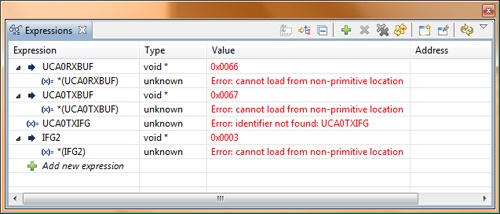
While in debug mode, I have added a couple expressions to the watch window: the receive buffer, UCA0RXBUF, and the transmit buffer, UCA0TXBUF. When I step through the ISR, these are the symptoms I see at those registers.

  1. Only the Delete key generates an interrupt that forces the CPU to enter the ISR. No other keys will generate the interrupt.
  2. The firmware is able to enter the body of the WHILE condition (line 48) and execute the assignment of UCA0RXBUF to UCA0TXBUF.
  3. The image below shows the Watch window and its contents after the ISR has been executed. The values 0x0066 and 0x0067 never change while the program runs.

It seems to me that the buffers are not getting filled with character data. And since the Delete key is the only key that triggers an interrupt, but without the ability to exchange a character either way, the signaling across the wire might be suspect. 

--------------------------------------------------------------------------------------------------

QUESTION 1

When I press a key on my keyboard, should the character for that key appear in the terminal window twice, with the first instance as an output from my keyboard and the second instance echoed from the device?

QUESTION 2

Why are my keystrokes not echoed in the terminal window?


--------------------------------------------------------------------------------------------------

DEMO PROGRAM

Here is the program that came directly from TI. No changes were made.

//******************************************************************************
//   MSP430G2xx3 Demo - USCI_A0, 9600 UART Echo ISR, DCO SMCLK
//
//   Description: Echo a received character, RX ISR used. Normal mode is LPM0.
//   USCI_A0 RX interrupt triggers TX Echo.
//   Baud rate divider with 1MHz = 1MHz/9600 = ~104.2
//   ACLK = n/a, MCLK = SMCLK = CALxxx_1MHZ = 1MHz
//
//                MSP430G2xx3
//             -----------------
//         /|\|              XIN|-
//          | |                 |
//          --|RST          XOUT|-
//            |                 |
//            |     P1.2/UCA0TXD|------------>
//            |                 | 9600 - 8N1
//            |     P1.1/UCA0RXD|<------------
//
//******************************************************************************
#include <msp430.h>

int main(void)
{
  WDTCTL = WDTPW + WDTHOLD;                 // Stop WDT
  if (CALBC1_1MHZ==0xFF)					// If calibration constant erased
  {											
    while(1);                               // do not load, trap CPU!!	
  }
  DCOCTL = 0;                               // Select lowest DCOx and MODx settings
  BCSCTL1 = CALBC1_1MHZ;                    // Set DCO
  DCOCTL = CALDCO_1MHZ;
  P1SEL = BIT1 + BIT2 ;                     // P1.1 = RXD, P1.2=TXD
  P1SEL2 = BIT1 + BIT2 ;                    // P1.1 = RXD, P1.2=TXD
  UCA0CTL1 |= UCSSEL_2;                     // SMCLK
  UCA0BR0 = 104;                            // 1MHz 9600
  UCA0BR1 = 0;                              // 1MHz 9600
  UCA0MCTL = UCBRS0;                        // Modulation UCBRSx = 1
  UCA0CTL1 &= ~UCSWRST;                     // **Initialize USCI state machine**
  IE2 |= UCA0RXIE;                          // Enable USCI_A0 RX interrupt

  __bis_SR_register(LPM0_bits + GIE);       // Enter LPM0, interrupts enabled
}

//  Echo back RXed character, confirm TX buffer is ready first
#pragma vector=USCIAB0RX_VECTOR
__interrupt void USCI0RX_ISR(void)
{
  while (!(IFG2&UCA0TXIFG));                // USCI_A0 TX buffer ready?
  UCA0TXBUF = UCA0RXBUF;                    // TX -> RXed character
}


  • Hi Thomas,

    Firstly, Launchpad has FET's on the board to help u communicate with Computer via UART. So you donot really need to pull out wires and use DB-9 connector to send info. 
    After you load the code in to Msp430. Open your device manage>>>Com and Lptt ports>> you will see "MSP430 Application UART (com X) " there. Which means u don't need any cables. At this stage u can open putty select serial and put the right com port in. click open and u will a terminal. Note: the terminal will not open if the COM port is open.

    If u need this DB9 connector any way then u need to have three wires,
    1.TXD
    2.RXD
    3. GND.

    from the reading that I have done over this e2e forum, you need to decare all pins of port 1 as out puts. so add
    try this

    int main(void)
    {
      WDTCTL = WDTPW + WDTHOLD;                 // Stop WDT
      if (CALBC1_1MHZ==0xFF)					// If calibration constant erased
      {											
        while(1);                               // do not load, trap CPU!!	
      }
      DCOCTL = 0;                               // Select lowest DCOx and MODx settings
      BCSCTL1 = CALBC1_1MHZ;                    // Set DCO
      DCOCTL = CALDCO_1MHZ;
      //
      P1DIR = 0xFF // from reading, select all pins as outputs
      //
      P1SEL = BIT1 + BIT2 ;                     // P1.1 = RXD, P1.2=TXD
      P1SEL2 = BIT1 + BIT2 ;                    // P1.1 = RXD, P1.2=TXD
      UCA0CTL1 |= UCSSEL_2;                     // SMCLK
      UCA0BR0 = 104;                            // 1MHz 9600
      UCA0BR1 = 0;                              // 1MHz 9600
      UCA0MCTL = UCBRS0;                        // Modulation UCBRSx = 1
      UCA0CTL1 &= ~UCSWRST;                     // **Initialize USCI state machine**
      IE2 |= UCA0RXIE;                          // Enable USCI_A0 RX interrupt
    
      __bis_SR_register(LPM0_bits + GIE);       // Enter LPM0, interrupts enabled
    }
    
    //  Echo back RXed character, confirm TX buffer is ready first
    #pragma vector=USCIAB0RX_VECTOR
    __interrupt void USCI0RX_ISR(void)
    {
      while (!(IFG2&UCA0TXIFG));                // USCI_A0 TX buffer ready?
      //Also if you want to know that this is really working 
        if(UCA0RXBUF == 0x61) // if key stroke is a
    	  UCA0TXBUF = 0x62;//output b
      // this code usually ecos back the same character at the   //same location so u donot cc 2 a's if u put a. 
      UCA0TXBUF = UCA0RXBUF;                    // TX -> RXed character
    }

    cheers


  • Sri-Sri:

    Thanks for the info. I'll give it a try this weekend. The reason I'm not using the path through the FET is because the FET is not going to be part of the final product.

    -Thomas

  • The signals in a DB-9 connector are most likely to be +12V or -12V. MSP430 cannot handle that.

  • old_cow_yellow said:

    The signals in a DB-9 connector are most likely to be +12V or -12V. MSP430 cannot handle that.

    You beat me to the punch. As I read that part of OP, I was thinking "NOOO!!!"

    You cannot connect MSP430 port pins directly to PC DE-9 serial port. OP will be lucky if he didn't permanently damage the port pins on his MSP430 device.

    And since it's a pet peeve, there is no such thing as a DB-9 connecter. The "B' size shell is used for 25-pin connectors. The 9-pin serial connectors use an "E" size shell and are technically known as DE-9.

  • Oh! No!!!!  What was I thinking! Oh, well. Maybe it'll still work. I'll check the voltages, divide them, put in a ground, and see what happens.

    Thanks for getting me straight about the DE-9. Good greif. And all these years I've been calling it a DB9, while DE-9 is right there in front of my face every time look at those specs! 

  • Well, I'm a real amatuer. I'm going to need a MAX232 chip to make the physical interface. I should have looked into this  before I assumed anything.

  • Take a MAX3232, as it is designed to run with 3.0V while the MAX232 is for 5V operation.

    Now about the other problems.

    Your watch expressions are wrong. UCA0RXBUF is not a void*, it is a global (pseudo) variable. The output is correct, 0x0066 is the memory location of this ‘variable’, the address of the UCA0RXBUF register. And of course it won’t change. However, the debugger cannot read from *(UCA0RXBUF). What is a void value? If UCA0RXBUF were an unsigned char *, well, things would be different.
    UCA0TXIFG is just a defined value. It has no location and its meaning wasn’t passed to the linker. The compiler was simply using the value it stands for when compiling the code.

    A1: when you press a character on your keyboard, the associated ASCII value will be sent out to the serial port. However, that’s all. Unless you have configured the terminal program to also print it on screen. But AFAIK this is not the default. Look for a ‘local echo’ setting. If something comes in, it will be shown. But as you already noticed, you won’t get anything in as the MSP is unable to receive what you send out due to hardware design problems.

  • Thank you. That is very helpful.

    I'll keep you all updated as to the progress of this matter, and respond with "Answered" when completed.

**Attention** This is a public forum