This thread has been locked.

If you have a related question, please click the "Ask a related question" button in the top right corner. The newly created question will be automatically linked to this question.

Using custom BSL/SBW

Other Parts Discussed in Thread: MSP430F5529, MSP430F5510, MSP430G2533, SN74LVC2G126, SN74LVC2G125

I’m working on a small board, and because of various constraints, it will be sealed and the only access to programming the MSP430 program flash will be through a USB, using a USB/UART converter chip. I’ve read through the appnote SLAU319 but I’m still not sure about the entire procedure. The target micro is a ‘G2533 or similar.

First question is about how to invoke the programming mode, including the first programming. The USB/serial chip has I/O pins that can be controlled with the PC software. Can I access the chip purely through the 9600 baud port, or do I have to diddle the RST/TST lines to access it? After first download, I’ll have a UART monitor running  - for  reprogramming, can I call a C-code procedure that will skip the RST/TST sequence? Is that what the “preparation for software call” in the appnote does? Could I skip the UART altogether and just bit-bang the RST/TST lines? That’s what the SBW appears to do.

SLAU319 shows the commands, but not a real typical programming sequence. Do you have an example that shows a complete download, from first bytes to programming a small program?


Thanks!

  • Hi Mike,

    Mike Kaelin said:
    Can I access the chip purely through the 9600 baud port, or do I have to diddle the RST/TST lines to access it?

    You need to invoke the BSL entry sequence using RST/TEST lines. 

    Mike Kaelin said:
    After first download, I’ll have a UART monitor running  - for  reprogramming, can I call a C-code procedure that will skip the RST/TST sequence? Is that what the “preparation for software call” in the appnote does?

    Correct. You can call the BSL from your application by jumping to the vector as shown in the AppNote.

    Mike Kaelin said:
    Could I skip the UART altogether and just bit-bang the RST/TST lines? That’s what the SBW appears to do.

    That's an option. You are correct saying that SBW only needs the RST/TST lines and you can use it to program the device; but it's important to mention that SBW is a bidirectional protocol which is more complicated than the UART approach. 

    At the end, you can use SBW, 4-wire JTAG or BSL to program MSP430s, but the main purpose of BSL is to provide an easier way to program the device, especially on the field if you are using a host processor.

    Now, if you don't have a host processor but you just need an interface to program the device, then you can just use SBW and a tool like the msp-fet430uif.

    Mike Kaelin said:
    SLAU319 shows the commands, but not a real typical programming sequence. Do you have an example that shows a complete download, from first bytes to programming a small program?

    I don't think we have a document per se, but I connected an analyzer while downloading a simple application to a G2553. The analyzer is a Saleae Logic.

    0045.BSL_G2553.logicdata

    My target device was:

    - G2553 running on launchpad

    my Host was:

    - Hardware: G2231 running on a launchpad as shown in this AppNote: http://www.ti.com/lit/an/slaa535a/slaa535a.pdf

    - PC Software: BSLDEMO2 (available in SLAU319). 

    If you have a second launchpad, I recommend you to check SLAA535, use it to test BSL and familiarize with it. 

    Another option is the BSL Rocket (https://www.olimex.com/Products/MSP430/BSL/MSP430-BSL/). 

    Check this wiki for some details on how to use it with F2xx: http://processors.wiki.ti.com/index.php/MSP430-BSL/Using_1xx_2xx_4xx

    Regards,

    Luis R


  • Mike Kaelin said:

    I’m working on a small board, and because of various constraints, it will be sealed and the only access to programming the MSP430 program flash will be through a USB, using a USB/UART converter chip. I’ve read through the appnote SLAU319 but I’m still not sure about the entire procedure. The target micro is a ‘G2533 or similar.

    You can use (open source) BSL (on PC side) prepared by TI with higher rate than 9600 bps. TEST / RESET lines must be used for BSL entry sequence. Bit-banging SBW over UART is not possible because of UART low speed. There are also some other non-BSL, boot loader (using UART) solutions, for example...

    http://forum.43oh.com/topic/3661-1k-serial-gdb-bootloader

  • Hi Luis,


    Thanks for a great answer. You've confirmed a lot of what I thought I understood from reading the appnotes.

    Like I said, my customer wants this completely sealed, and the whole board will be about a half-inch square, so the normal MSP430UIF is not an option. I basically need laptop USB directly to 'G2xxx programming. It's no problem to put in the TST/RST control lines for BSL entry, but it seems to me like that customizes it enough that a "standard" USB download program wouldn't work.That's really the crux of my confusion - how do I get from a standard download program to the TST/RST/RX/TX pins that are defined in the appnote? Is there a GUI version of BSLDEMO (i.e. not a command line) or some other windows-based downloader?

    I'm  not anxious to write my own download utility.There are several USB/UART converter chips available, and I assume that the setup to control the programmable I/O is not a standard, so a generic PC program would have to either handle multiple USB chips, or be specific to one or the other. Or maybe I run a short program that does the TST/RST sequence with my chosen USB/UART chip, then call BSLDEMO? I could do that for the factory programming, and thereafter send a command via UART to start the BSL.

    It's an option for me to get the Saleae Logic, but I've already got a couple of analyzers... just in case I do have to write my own downloader, any chance you could send me a couple of screen shots of the sequence - if it's long, you can skip the downloaded program, I just want to see the sequence leading up to it and maybe the finish.


    Thanks, Mike.

  • Hi Zrno,


    Thanks! The link you provided is interesting, but my customer wants this sealed up and programmed only through the USB (including first download). Like I said in my reply to Luis, the missing link is getting from a standard (?) downloader program to the TEST/RST/RX/TX pins. There will be a USB/UART adapter (with possibly some programmable I/O pins) between PC and micro, but nothing else.


    If I connect a (generic) USB/UART chip so that DTR goes to reset and RTS goes to the TEST line, will download work with any software that downloads via the MSP430UIF? And if so, (not that I really need it) would debugging also work through this interface? Does TI have a GUI based downloader (i.e. not a DOS command line!)

    Thanks, Mike.

  • I made my own software/hardware BSL, SBW and bootloader, so it is possible if you have some special reason for this, and large amount of free time. In this case there is also USB bit-banging possibility that enable direct connection of MSP430G2xx to USB with same simple glue logic.

    http://forum.43oh.com/topic/2962-bit-bang-usb-on-msp430g2452

    In any other case you need one extra IC on board.

    If you want BSL, than extra IC will be USB-UART bridge chip that also have possibility to control TEST/RESET lines (and AFAIK all of them have it). You don't need 2 USB-UART bridges, because it can be used for BSL and normal (not programming) communication with PC, but TX/RX pins will be fixed to timer pins (because of BSL) on MSP430, so software UART must be used, not hardware. If you have some communication where is known who is sending to who, what size, and when, no problem at all.

    http://forum.43oh.com/topic/1284-software-async-serial-txrx-without-timer

    If you want SBW (with USB-UART bridge possibility) than extra IC will be MSP430F5xx. You can use original open source MSP430F5529 LP project and shrink it down to 32 KB, so it can fit on low-cost, small size, MSP430F5510.

    http://processors.wiki.ti.com/index.php/MSPDS_Open_Source_Package

  • Hi Zrno,

    Consider this a "least time and effort" design. I don't want to develop any PC software if I don't have to.

    This is what I'm planning: a standard USB/UART bridge (for example CP2102, FT234XD, FT230X - these all have USB to 3.3V UART plus a couple of programmable pins) connected to an MSP430G2533. The bridge UART pins are connected to the MSP430 UART pins, with glue logic like inverters if necessary. DTR from the ridge is connected to RESET and RTS is connected to TEST. This is pretty similar to what is described in the appnote SLAU319H chapter 4.

    So, I have more or less replicated the appnote hardware. Without doing anything to the DTR/RTS pins, I will have USB/UART communications to the MSP430.

    Now, my question is, will some currently available PC software download an MSP430 text file to program the part? Is it going to be dependent on the bridge chip, or will it just control the DTR/RTS pins to invoke the BSL, and the bridge driver will handle it from there?

    Which programs will work? One of the programs included in one of the appnotes? Will the IAR debugger program it directly? Not necessary, but would it also debug with this interface? There used to be a little windows-based program called MSPFET that would download txt files using the MSP430 USB FET tool, will that work?

    Thanks, Mike.

  • BTW, is there an error in appnote SLAU319? I'm looking at version H that I downloaded a a couple of days ago, and for the G2xx3 it shows the TX connected to P1.1 (per datasheet UCA0RXD) and RX connected to P1.5 (UCA0STE). Shouldn't that be P1.2 (UCA0RXD)?


    Thanks, Mike.

  • sorry, mistyped and can't edit posts - P1.2 is UCA0TXD.

  • Mike Kaelin said:

    Now, my question is, will some currently available PC software download an MSP430 text file to program the part? Is it going to be dependent on the bridge chip, or will it just control the DTR/RTS pins to invoke the BSL, and the bridge driver will handle it from there?

    Which programs will work? One of the programs included in one of the appnotes? Will the IAR debugger program it directly? Not necessary, but would it also debug with this interface? There used to be a little windows-based program called MSPFET that would download txt files using the MSP430 USB FET tool, will that work?

    For example...

    http://www.flyingcampdesign.com/msp430-bsl-programmer.html

    For programing can be used TI open source BSL tool (slau319 MSP430 Programming Via the BSL), and bridge will work like USB-UART bridge, virtual serial port (CDC), without any special driver (except one for bridge chip).

    BSL is used only for flashing, not for debugging (SBW / JTAG), and AFAIK it is not supported by software used with FET debuggers.

    Repeat, only "problem" is that you are forced to software UART on MSP430, because of BSL (RX/TX lines). You can't use MSP430 hardware UART because hardware RX/TX pins are different that one used by BSL.

  • Yes! The FlyingCampDesign docs demonstrate exactly what I want... I'm OK not using this circuit for debugging, I was just curious about that. I'll order a couple to play with.

    I'm not sure I understand your last statement though - is there a reason why the UART can't be used for both normal communications and the BSL? Either I'm using the MSP430 UART to talk to the USB port, or the USB takes control of the MSP430 for the BSL function. They don't have to work at the same time.

    Is it possible that I need to disable the RTS/DTR pins if I want to just have a standard USB UART?

  • Hi Mike,

    As you noticed, G2xx3 uses P1.1 and P1.5 for BSL which don't correspond to the USCI pins, and not only that, but P1.1 has a different functionality (TX instead of RX). The reason for this is that BSL is implemented as a Timer-based UART. 

    As zrno mentions, you would have to use a "Software" UART instead of using USCI, or you would need a hardware solution.

    So, for HW:

    * Your interface can be USB, but you should consider the following:

       -  your USB-UART bridge needs to have control of DTR/RTS to force the entry sequence.

       - The Rocket-BSL (mentioned in previous thread) does that by implementing a USB-UART bridge with a MSP430F55xx.

       - As mentioned, the FCD-PRG01 does something similar with a FT232R.

       - You'll only have access to BSL, not SBW/JTAG, so you can only program the device, not debug it.

       -  As mentioned above, the pins used for BSL are not the same as USCI.

    * If you don't add the USB connector but you make available TXD, RXD, RST and TEST to use BSL:

     - You'll probably need to make a custom adapter if you want a small connector

      - You can use your own external USB-UART bridge, or you could use something like the Rocket-BSL, or Elprotronic's FlashPro430 (http://www.elprotronic.com/flashpro430.html) 

    * With RST and TEST you can use SBW:

     - You'll probably need to make a custom adapter if you want a small connector

      - You can use something like the MSP-FET430UIF 

     - You can download and debug

    And for SW:

    * If you use BSL:

      - BSLDEMO in SLAU319 is available as .exe and also as source 

      - Flying Camp has an open source GUI

     - Python tools (https://pypi.python.org/pypi/python-msp430-tools)

    * SBW:

     - IDEs such as IAR, CCS

      - MSP430 Flasher (http://processors.wiki.ti.com/index.php/MSP430_Flasher_-_Command_Line_Programmer)

      - FET-Pro430 (http://www.elprotronic.com/download.html)

    Regards,

    Luis R

  • Hi Luis,

    I will be using the BSL similar design to the FlyingCamp board, either with a FT232 or a CP2102 (which the customer has in his stock already).


    Is it just the G25x3 that is bit-banging the BSL UART, or all the G series? Is the F2xxx family using the UART peripherals or do they bit bang too? If all of the parts are bitbanging the BSL, is there a reason why I couldn't put the BSL pins in parallel with the UART peripheral pins?

    Again, many thanks for clearing this up!

    Mike.

  • Hi Mike,

    Mike Kaelin said:
    Is it just the G25x3 that is bit-banging the BSL UART, or all the G series?

    Some G2xx (G2xx0/1/2) don't have BSL at all, but in this case you could use a bootloader which resides in Main Flash such as MSPBoot (http://www.ti.com/lit/pdf/slaa600).

    All others G2xxx have a Timer-based (aka bit-banged) UART. For example, if you look at G2744 you'll notice that BSL uses pins P1.1/P2.2 and USCI-UART uses P3.4/P3.5.

    Mike Kaelin said:
    Is the F2xxx family using the UART peripherals or do they bit bang too?

    All F2xx have a ROM BSL using Timer-based UART.

    Just FYI, F5xx have different options and in many cases, they also use timer-based UART. In this case, the BSL resides in Flash, so it can also be modified according to particular needs (i.e. different pins, different entry sequence, etc).

    Mike Kaelin said:
    If all of the parts are bitbanging the BSL, is there a reason why I couldn't put the BSL pins in parallel with the UART peripheral pins?

    That should be OK. The pins are configured as input after reset so the USCI pins shouldn't conflict with BSL pins in BSL mode; in the same way, in your application you just have to make sure that the BSL pins don't conflict with USCI.

    G2xx3 is a little difficult because P1.1 is used as TXD in BSL, but as RXD when using USCI. I don't know the pin assignment for ALL the devices but as far as I remember, this is the only device with such pin assignment.

    Regards,

    Luis R

  • Thanks to both of you - Great Job!

  • Mike,

    You got good responses and seems all set to go. However, the following points might still help.

    1) Most USB to serial chips provide 3.3V I/O, but most ready made USB to serial cables convert those 3.3V I/O to +/- 12V RS232 levels which is not compatible with G2553. So you need to by-pass that or convert them back to 3.3V.

    2) The "modem control signals" DTR and RTS, if in 3.3V, can be used as nRST and TEST for G2553. The PC program can control those signals to do the BSL entrance sequence.

    3) The PC program BSLDEMO2 does almost exactly the above. But it might have inverted DTR. You can download the source code, change the DTR usage, and recompile it.

    4) Elprotronic (even the Free version) can use BSL too. It use Windows GUI. Check it out!

  • Mike Kaelin said:

    I will be using the BSL similar design to the FlyingCamp board, either with a FT232 or a CP2102 (which the customer has in his stock already).

    You can search on net, for device that have most stable drivers (working on all OS's), highest BR, and low price. Maybe there is better device than costumer have in stock already.

    Your MSP430x2xx device will use forever bridge chip for communication with PC, so there is no more 115200 bps limitation, it can go over this...

    http://forum.43oh.com/topic/3413-msp430-uart-benchmark/?p=34429

    Mike Kaelin said:

    Is it just the G25x3 that is bit-banging the BSL UART, or all the G series? Is the F2xxx family using the UART peripherals or do they bit bang too? If all of the parts are bitbanging the BSL, is there a reason why I couldn't put the BSL pins in parallel with the UART peripheral pins?

    You can use software UART, but if you can find some extra space on board there is elegant solution, that enables BSL and hardware UART, and cost less than nothing.

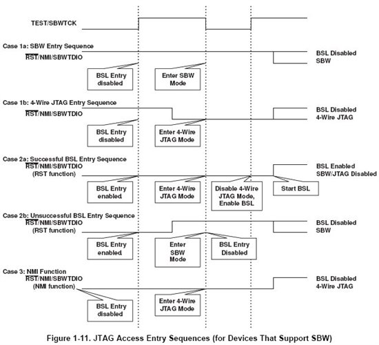
    Here you can see BSL / SBW / JTAG entry sequence (case 3 where at the end BSL is enabled) from slau320...

    During normal program running (when bridge is used for non-BSL communication) TEST pin on MSP430 will be low. During BSL running (flashing), TEST pin will be high. You can use sn74lvc2g125 and sn74lvc2g126 with TEST signal for enabling / disabling gates. When TEST is low, sn74lvc2g125 will enable hardware UART lines and sn74lvc2g126 will disable BSL UART lines, and opposite.

**Attention** This is a public forum