This thread has been locked.

If you have a related question, please click the "Ask a related question" button in the top right corner. The newly created question will be automatically linked to this question.

Whats the algorithm used to convert analog signals to be shown on display?

Other Parts Discussed in Thread: MSP-EXP430FR5969

Hello!

I need to read a analog signal using the ADC_12B and show the respective voltage on a 96x96 display. Like a multimeter.

Whats the algorithm that is used to convert this signal and show it on display? I'm using the MSP430 F5969 and the Sharp LCD.

Thanks!

  • Atiom said:

    I need to read a analog signal using the ADC_12B and show the respective voltage on a 96x96 display. Like a multimeter.

    Whats the algorithm that is used to convert this signal and show it on display?

    Same algorithm as for most of ADC's :) Further reference:

    http://en.wikipedia.org/wiki/Analog-to-digital_converter

    If you have any questions about "Resolution" chapter you are advised to read - feel free to come back and ask.

  • I meant the algorithm used to display the value. Not the algorithm used to convert analog signals to its digital form.

    Thanks!

  • You know, after I have gotten the digital value of that analog signal, for example 0x01A8, how do I represent it as a decimal number and show it on a display?

  • Hexadecimal 0x01A8 is the same as decimal 424. But that is probably not what you want either. You need to know the Reference Voltage used for ADC, and if possible, the calibration constants, to calculate the number of mV it represents.

    As for displaying on the Sharp 96x96 LCD, you need to prepare a 96x96 bit map image of in memory; and then use I2C interface to sent those memory to the LCD controller. The Graphic Library probably has routines to help you to construct that bit map image. It is a tedious and boring.

  • I have looked at the Graphic Library but have not found any routine to help me out on doing this bit map image.

    Is this the only way to do that?

    Help me out people, I'm kind of lost can't think of anything to accomplish it.

    Thanks so far!

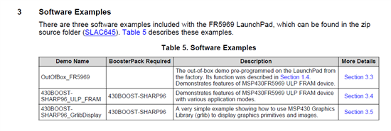
  • The "out of the box experience" code that was pre-loaded into the FR5969 LP + LCD bundle uses that Graphics Library. The source code can be found at TI web-site too.

    Of course there are other ways to do that. I think the easiest way is to ask, order, or enlist someone else to do it. And (perhaps only to me) the hardest way is to use a Library. I would not do either of the above. I would rather do it myself from scratch and make compromises as I see fit.

    If you really want, I can describe what I would do if I were to do it. It is tedious and boring. And I doubt if it is of any use to you. That is why I pointed to the Graphics Library. Which is also tedious and boring (beyond my tolerance) but is generally accepted by others.

  • I have the Graphics Library installed, but I have not found any routine that helps doing that. I have never done such thing, so I might be missing something.


    As I have no clue what to do, I would really appreciate to learn from you how you would do it, be it using the Graphics Library or your very way to do it.


    Thank you in advice!

  • I still think you should find examples and libraries form TI to do it the normal way. According to MSP-EXP430FR5969 LaunchPad™ Development Kit User's Guide
    (SLAU535A.pdf Revised June 2014),


    And I have seen SLAC645C.zip with all those source files at one time. But I cannot locate this files now. Maybe Katie Pier or someone else from TI will jump in and help you on that.

    The Sharp 96*96 LCD bit-map consists of (96/8)*96=1152 (or 0x0480) bytes. The 8 bits of each byte are spread out horizontally, most significant bit on the left and least significant bit on the right. It takes 96/8=12 bytes from left to right to map each single row of pixels and there are 96 rows, from top to bottom.

    I am not professional and very old. My way of doing things are arcane. If I were to do it just to show some numbers. This is what I would do.

    I would first write 0’s in all these 1152 bytes. I would then robber-stamp numerals and other symbols at various parts of this clean slate. When that is all done, I would just transmit these 1152 bytes to the LCD via I2C interface.

    Because I am lazy and cheap, I have just a few robber-stamps and they are all rectangular in shape and of the same size, 8*7 pixels. To save the trouble of shifting bits and crossing byte boundaries, I limit myself to position my stamping in the horizontal direction to only 12 possible choices, 8 pixels apart, that are aligned with the byte boundaries. Hence x=0,1,2,3,…,11. I could, also limit myself to position the stamping in the vertical direction to 8 possible choices, 12 pixels apart. Hence y=0,1,2,3,…,7.
     
    Each of these robber-stamps consists of 7 bytes. Here are two examples, for the numeral 5 and 9.

  • Great explanation!!! That's all I needed.

    Thank you very much :)

**Attention** This is a public forum