This thread has been locked.

If you have a related question, please click the "Ask a related question" button in the top right corner. The newly created question will be automatically linked to this question.

EVM430-F6736 connection

Other Parts Discussed in Thread: EVM430-F6736

Hi,

I don't have EVM430-F6736 board but I use its design guide and schematics to build a simpler board. 

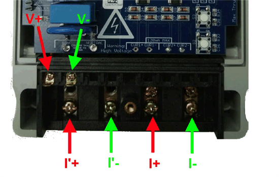
I could not really understand how to connect load from the design files. I expect to have Line and Neuter in and out pins, e.g.

However, I only see V+ and V- input connections.

Do I suppose to have V+ and V- out connector on the circuit?

  • It seems that in the first image, connections for a direct metering approach is used. Here either 1+2 or 3+4 are shorted while the other pair is connected by a shunt, to measure the current.

    The first image seems to be for use with current transformers, where you need line and neutral for supply and momentary voltage metering, and the load currents are galvanically separated by current transformers. The load current doesn’t flow through the meter, only a transformed fraction of it.
    We build energy meters where the load current is up to 2000A, while the transformed current into the e-meter is only 66mA. The meter has 3*V+ inputs and 3*I pairs and can be used for three-phase or triple single-phase metering. And it can be mounted while the load is operating (clip transformers that can be clipped around the line wire/bar )

**Attention** This is a public forum