This thread has been locked.

If you have a related question, please click the "Ask a related question" button in the top right corner. The newly created question will be automatically linked to this question.

Issue with UART Code on MSP430G2553

Other Parts Discussed in Thread: CC2541, MSP430G2553

Hi guys,

I've been working on a UART link between an MSP430G2553 and a CC2541. I've managed to get the CC2541 to send over a byte, repeated over and over at a baud rate of 115,200 

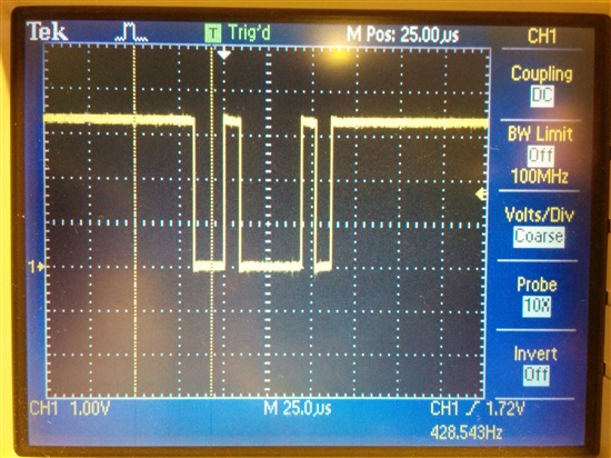
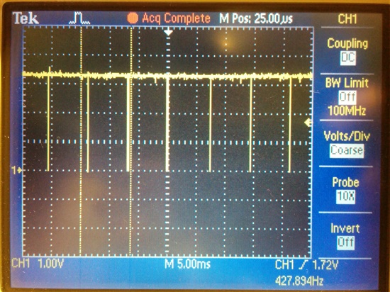
I've also managed to receive and echo the received byte on the MSP430 end, and confirmed that the value I am sending is in fact what is read on the Rx and transmitted on the Tx pins of the MSP430, using an oscilloscope to check the bits (I read 0b01000010, which is 66 in decimal, what I was trying to send).

The issue I'm having is that I can't seem to get an LED on my launchpad (which has the MSP430G2553) to light based on a conditional if statement (see below). The LED seems to light regardless of what value I set UCA0RXBUF equal to. In other words, it always lights up.

I've tried writing the if statement in 2 ways:

1) if (UCA0RXBUF == 66)

2) if (UCA0RXBUF & 0x42)

#include <msp430.h>

int main(void)
{
    WDTCTL = WDTPW + WDTHOLD;                 // Stop WDT

    volatile unsigned int i;

    /* Use Calibration values for 8MHz Clock DCO*/
    DCOCTL = 0;
    BCSCTL1 = CALBC1_8MHZ;
    DCOCTL = CALDCO_8MHZ;

    /* Configure Pin Muxing P1.1 RXD and P1.2 TXD */
    P1SEL = BIT1 | BIT2 ;
    P1SEL2 = BIT1 | BIT2;

    P1DIR |= 0x01;

    /* Place UCA0 in Reset to be configured */
    UCA0CTL1 = UCSWRST;

    /* Configure */
    UCA0CTL1 |= UCSSEL_2;                     // SMCLK
    UCA0BR0 = 69;                            // 8MHz 115200
    UCA0BR1 = 0;                              // 8MHz 115200
    UCA0MCTL = UCBRS0;                        // Modulation UCBRSx = 1

    /* Take UCA0 out of reset */
    UCA0CTL1 &= ~UCSWRST;

    /* Enable USCI_A0 RX interrupt */
    IE2 |= UCA0RXIE;

    if (UCA0RXBUF & 0x42)
        {
        	P1OUT |= BIT0;				// Set P1.0 High

        	i = 30000;					// SW Delay
        	do i--;
        	while(i != 0);

        	P1OUT &= ~BIT0;				// Set P1.0 Low
        }
        else
        {
        	P1OUT &= ~BIT0;
        }

    __bis_SR_register(GIE);       // Enter LPM0, interrupts enabled
}

/*  Echo back RXed character, confirm TX buffer is ready first */
#pragma vector=USCIAB0RX_VECTOR
__interrupt void USCI0RX_ISR(void)
{

    while (!(IFG2&UCA0TXIFG));                // USCI_A0 TX buffer ready?
    UCA0TXBUF = UCA0RXBUF;                    // TX -> RXed character

}

  • Also, here are 2 pics of the UART signal, zoomed in and zoomed out

  • what is the first value you put in the UCA0TXBUF?

    Which values are in the UCA0TXBUF and UCA0RXBUF before you release the uart reset? previous test value if you did not remove the power supply?

  • yes, the values in the UCA0TXBUF and UCA0RXBUF before I release the uart reset are the previous test value (the uint8 66)

  • The way this is written, you only test the input byte once, before any input byte could possibly have arrived. You should probably enclose the entire if/else block into a while(1) loop.

    What is the significance of (UCA0RXBUF & 0x42)[!=0]? This will be true for your test byte ('B'), or indeed for any alphabetic, but only for some numerics, and a random collection of other characters.

  • Hi Bruce,

    So I added the while(1) loop into my code and uploaded the following to my launchpad:

    When I use the line of code: if (UCA0TXBUF != 0x42), the LED blinks and stays off

    and when I use the line of code: if (UCA0TXBUF != 0x41), if (UCA0TXBUF != 0x40), etc., the LED turns on and stays on indefinitely

    So it seems that is definitely better, in that at least there is a distinction in the response of the LED that is dependent on the correct byte value being referenced in the if statement

    However, would you happen to know why the LED blinks at all in the if (UCA0TXBUF != 0x42) case?

    #include <msp430.h>
    
    int main(void)
    {
        WDTCTL = WDTPW + WDTHOLD;                 // Stop WDT
    
        volatile unsigned int i;
    
        /* Use Calibration values for 8MHz Clock DCO*/
        DCOCTL = 0;
        BCSCTL1 = CALBC1_8MHZ;
        DCOCTL = CALDCO_8MHZ;
    
        /* Configure Pin Muxing P1.1 RXD and P1.2 TXD */
        P1SEL = BIT1 | BIT2 ;
        P1SEL2 = BIT1 | BIT2;
    
        P1DIR |= 0x01;
    
        /* Place UCA0 in Reset to be configured */
        UCA0CTL1 = UCSWRST;
    
        /* Configure */
        UCA0CTL1 |= UCSSEL_2;                     // SMCLK</em>
        UCA0BR0 = 69;                            // 8MHz 115200</em>
        UCA0BR1 = 0;                              // 8MHz 115200</em>
        UCA0MCTL = UCBRS0;                        // Modulation UCBRSx = 1</em>
    
        /* Take UCA0 out of reset */
        UCA0CTL1 &= ~UCSWRST;
    
        while(1){
    
        /* Enable USCI_A0 RX interrupt */
        IE2 |= UCA0RXIE;
    
        P1OUT &= ~BIT0;
    
        if (UCA0RXBUF != 0x42)
            {
                P1OUT |= BIT0;              // Set P1.0 High</em>
    
                i = 30000;                  // SW Delay</em>
                do i--;
                while(i != 0);
    
                P1OUT &= ~BIT0;             // Set P1.0 Low</em>
            }
            else
            {
                P1OUT &= ~BIT0;
            }
    
        __bis_SR_register(GIE);       // Enter LPM0, interrupts enabled</em>
        }
    }
    
    /*  Echo back RXed character, confirm TX buffer is ready first */
    #pragma vector=USCIAB0RX_VECTOR
    __interrupt void USCI0RX_ISR(void)
    {
    
        while (!(IFG2&UCA0TXIFG));                // USCI_A0 TX buffer ready?</em>
        UCA0TXBUF = UCA0RXBUF;                    // TX -> RXed character</em>
    
    }
    

  • The first time this code looks at the RXBUF is almost certainly before any incoming byte has arrived.

    The Book says that before the first byte has arrived (after a reset) the contents of the RXBUF are "undefined" -- maybe 0, maybe the last byte that arrived before the reset, maybe random junk. If you suppose it's random, it has only a 1/256 chance of being a 0x42. When it (probably) isn't, the LED delay may hold the program back long enough for the first byte to arrive.

    The fundamental problem here is that the code has no interlock between data arrival (ISR in this case) and what the foreground (main) does. Each time through the loop, 0, 1, 2, or more bytes may have arrived since the last time.

    I realize that this code is just an experiment, but by the time you write the final code you'll have to interlock your logic with data arrival. A common solution is to have the ISR put each byte into a circular buffer and have main pull it out.

  • Hi again Bruce,

    Thanks for your answer-that helped a lot. Do you have any references or ideas on how I could begin to modify my Rx ISR to create a circular buffer?

**Attention** This is a public forum