This thread has been locked.

If you have a related question, please click the "Ask a related question" button in the top right corner. The newly created question will be automatically linked to this question.

MSP430 ADC12 gives different value every time

Other Parts Discussed in Thread: MSP430FR5969

Hi, I am doing an interface of MSP430FR5969 with an image sensor.

So, I have this ADC settings. The adc input is connected to the analog out of the sensor 

void initADC()
{
while(REFCTL0 & REFGENBUSY); // If ref generator busy, WAIT
REFCTL0 |= REFVSEL_1 + REFON; // Select internal ref = 2V

// Configure ADC12
ADC12CTL0 = ADC12SHT0_1 | ADC12ON; // Sampling time,  ADC12 on
ADC12CTL1 = ADC12SSEL_3 | ADC12SHP ; //sample-hold, SMCLK 8MHz, repeat-single channel // Use sampling timer
ADC12CTL2 |= ADC12RES_2; // 12-bit conversion results
ADC12MCTL0 |= ADC12INCH_3 | ADC12VRSEL_1 | ADC12DIV_1 ; // A3 ADC input select; Ref 0-2V, ADC 4MHz
ADC12IER0 |= ADC12IE0; // Enable ADC conv complete interrupt
}

But the problem is that when i read every pixel of the image array, it is quite noisy. When I tried to sample each pixel 30 times and average it, it gives me a decent image but this is surely wasting time. So i thought that there is no problem with the image analog out but when I sampled the output several times, it gave me a different result, which should not be. I have tried to play with the clock, sampling time (regarding with the minimum tSample), and everything as slow as possible but the result still the same. Any suggestion?

  • 1. Are you sure that the input analog signal isn't noisy?

    2. You didn't specify a definition of "quite noisy", which are subjective terms. What is the sample spread you get versus what you think an acceptable sample spread should be?

    3. Have you done the impedance analysis to make sure the sample time is correct?

    4. Do you have any filtering on the sensor analog output to try to limit the signal to the band of interest?

    5. Is your MSP's AVcc supply adequately filtered and decoupled from DVcc?

  • SHT0_1 is quite a short sampling time. Is your sensor low-impedance enough for such a short sampling time?

    ADC12DIV_1 doesn’t belong into ADC12MCTLx. There is an ADC12DIF bit in ADC12MCTLx, which selects differential  mode. But this is bit 13 while ADC12DIV_1 sets bit 5, which is reserved.

    You probably meant to set ADC12DIV_1 in ADC12CTL1 for 4MHz ADC12CLK, but currently, you operate the ADC at 8MHz which is way above the specs. ;)

  • 1) Yes, I have checked it with oscilloscope.

    2) I have shifted my 12-bit ADC by 4 cause I can only take 8 bits, a noise on the result then means a really bad sampling error

    3) I have tried with the slowest sampling time but the result stays the same. But how do I actually measure the impedance of my camera? so that I can put it into the equation for impedance analysis.

    4) I don't need this as I will sample a DC signal

    5) I'm using MSP development board so I guess yes

  • Thanks for the answer,

    I have tried ranging SHT to _10 but still gives me a noisy image. How could I measure the impedance of my sensor?

    and about the DIV, thanks, I will try this again but since I have tried so many possibilities, even by changing SMCLK without DIV, the image result was still noisy.

    The specs say 0.8-5.4MHz, as far as i remember, but could you explain to me why a higher ADC clock rate is not suggested?

    Regards,

  • You can attach an external R/C filter. Or you can use the internal sampling cap as C and add a series resistor to the input. This works as low-pass and averages the noise on hardware level.

     You're tlaing about a camera? Note that light sensors output (such as CCD) is never DC - it is usually quite noisy.

    Teh impedance can be measured if oyu have a constant sendor output, check its level with a scope, then add a resistor to GND. The resistor forms a voltage divider with the intrernal impedance an dyou can calculate the 'inner' resistance by the change of the output signal. For measuring the ineer inductance or capacitance, you'll  also need to see the phase change, which is difficult.

    Reardign ADC12CLK limitations:

    A higher frequency than ~5MHz (and lower than 0.5MHz) is not recommended because of the way the ADC works. "The" sampling capacitor is actually an array of capacitors with different capacitance. Their ‘bottom’ sides can be switched independently between Vref+ and Vref-. So charge flows form one capacitor to the other while the result is compared to VRef+ for the individual bits. If the frequency is too high, the charge cannot flow completely, and the results are wrong (even in higher bits). If the clock speed is too low, Charge gets lost over time and the result is not precise too.

  • Jens-Michael Gross said:
    Note that light sensors output (such as CCD) is never DC - it is usually quite noisy.

    I would say: output of CCD usually is complex waveform and it is paramount to sample pixels at right time.

    More info here, Figure 1.

    Usually ADC sampling is synced to CCD pixel clock, with some delay skew.

  • Ilmars said:
    I would say: output of CCD usually is complex waveform and it is paramount to sample pixels at right time.

    That’s true too. You can’t simply sample each pixel. You need to do massive oversampling, detect the start of a pixel cycle, and get the plateau voltage (reference) and the data voltage (lowest voltage right before it rises again). And the real result is the quotient of the two, as the reference level is subject to change too, based on overall brightness or otehr influences.

  • Jens-Michael Gross said:
    get the plateau voltage (reference) and the data voltage (lowest voltage right before it rises again)

    You need to do this only when high enough precision needed - for photo or video applications. For instance most flatbed document scanners and also barcode scanners uses "black calibration" pixels at the beginning of linear CCD to set reference voltage, then just sample "data voltage" of each pixel.

  • Hi, thanks for the answer, yes! timing does really matter, i'm using photodiode vision sensor but I need to sample it at specific time especially when indoor since the lighting could introduce AC noise. So, setting the lowest hold time could actually deteriorate the result.

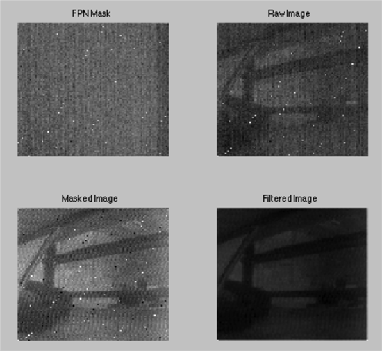
    But now, I have a new problem, I got this white random spots from the ADC on (fpn and raw image) that worsen my result (masked image). And this happens every time i acquire image. What do you think the problem is? I have attached also my code under. I have tried reducing ADC clock, ranging voltage reference, but still, random white spots.

    void getImage(short *image, unsigned char rowstart, unsigned char numrows, unsigned char rowskip, unsigned char colstart, unsigned char numcols, unsigned char colskip)
    {
    short *pimg = image; // pointer to output image array
    // unsigned char chigh,clow;
    unsigned char row,col,i;

    PORT_CAM_OE |= CAM_OE;
    ADC12CTL0 |= ADC12ENC;
    //sendByUART("start ADC", 9);

    // Go to first row
    setPointerValue(REG_ROWSEL,rowstart);

    // Loop through all rows
    for (row=0; row<numrows; row++) {

    // Go to first column
    setPointerValue(REG_COLSEL,colstart);

    // Loop through all columns
    for (col=0; col<numcols; col++) {
    __delay_cycles(8);
    // pulse amplifier if needed
    if (useAmp == 1)
    {
    pulseInphi();
    }

    while(REFCTL0 & !REFGENRDY);

    // get pixel value from ADC
    ADC12CTL0 |= ADC12SC; // Start sampling/conversion

    __bis_SR_register(LPM0_bits | GIE); // LPM0, ADC12_ISR will force exit
    __no_operation();


    *pimg = pixelValue; // store pixel
    pimg++;
    incValue(colskip); // go to next column
    }
    setPointer(REG_ROWSEL);
    incValue(rowskip); // go to next row
    }

    /*if((ADCType!=SMH1_ADCTYPE_ONBOARD)&&(ADCType!=SMH1_ADCTYPE_MCP3201_2))
    setADCInput(anain,0);*/
    ADC12CTL0 &= ~ADC12ENC;// disable chip
    PORT_CAM_OE &= ~CAM_OE;
    //sendByUART("end ADC", 7);

    }

    #pragma vector = ADC12_VECTOR
    __interrupt void ADC12_ISR(void)
    {
    switch(__even_in_range(ADC12IV, ADC12IV_ADC12RDYIFG))
    {
    case 0: break; // Vector 0: No interrupt
    case 2: break; // Vector 2: ADC12MEMx Overflow
    case 4: break; // Vector 4: Conversion time overflow
    case 6: break; // Vector 6: ADC12HI
    case 8: break; // Vector 8: ADC12LO
    case 10: break; // Vector 10: ADC12IN
    case 12: // Vector 12: ADC12MEM0 Interrupt

    while(ADC12CTL1 & ADC12BUSY);

    pixelValue =ADC12MEM0; // adc 12 bit conversion

    __bic_SR_register_on_exit(LPM0_bits); // Exit active CPU

    break; // Clear CPUOFF bit from 0(SR)
    case 14: break; // Vector 14: ADC12MEM1
    case 16: break; // Vector 16: ADC12MEM2
    case 18: break; // Vector 18: ADC12MEM3
    case 20: break; // Vector 20: ADC12MEM4
    case 22: break; // Vector 22: ADC12MEM5
    case 24: break; // Vector 24: ADC12MEM6
    case 26: break; // Vector 26: ADC12MEM7
    case 28: break; // Vector 28: ADC12MEM8
    case 30: break; // Vector 30: ADC12MEM9
    case 32: break; // Vector 32: ADC12MEM10
    case 34: break; // Vector 34: ADC12MEM11
    case 36: break; // Vector 36: ADC12MEM12
    case 38: break; // Vector 38: ADC12MEM13
    case 40: break; // Vector 40: ADC12MEM14
    case 42: break; // Vector 42: ADC12MEM15
    case 44: break; // Vector 44: ADC12MEM16
    case 46: break; // Vector 46: ADC12MEM17
    case 48: break; // Vector 48: ADC12MEM18
    case 50: break; // Vector 50: ADC12MEM19
    case 52: break; // Vector 52: ADC12MEM20
    case 54: break; // Vector 54: ADC12MEM21
    case 56: break; // Vector 56: ADC12MEM22
    case 58: break; // Vector 58: ADC12MEM23
    case 60: break; // Vector 60: ADC12MEM24
    case 62: break; // Vector 62: ADC12MEM25
    case 64: break; // Vector 64: ADC12MEM26
    case 66: break; // Vector 66: ADC12MEM27
    case 68: break; // Vector 68: ADC12MEM28
    case 70: break; // Vector 70: ADC12MEM29
    case 72: break; // Vector 72: ADC12MEM30
    case 74: break; // Vector 74: ADC12MEM31
    case 76: break; // Vector 76: ADC12RDY
    default: break;
    }
    }

    void initADC()
    {
    while(REFCTL0 & REFGENBUSY); // If ref generator busy, WAIT
    REFCTL0 |= REFVSEL_1 + REFON; // Select internal ref = 1.2

    // Configure ADC12
    ADC12CTL0 = ADC12SHT0_1 | ADC12ON; // Sampling time, S&H=16, ADC12 on
    ADC12CTL1 = ADC12SSEL_3 | ADC12SHP | ADC12DIV_1 ; //sample-hold, SMCLK, repeat-single channel // Use sampling timer
    ADC12CTL2 = ADC12RES_2; // 12-bit conversion results
    ADC12MCTL0 |= ADC12INCH_2 | ADC12VRSEL_1; // A3 ADC input select; Vref=AVCC
    ADC12IER0 |= ADC12IE0; // Enable ADC conv complete interrupt
    }

  • Irmandy Wicaksono said:
    I have tried reducing ADC clock, ranging voltage reference, but still, random white spots.

    You can't get good results out of CCD sensor if you don't sync your ADC sampling clock to CCD pixel clock.

    What sensor do you use? Any datasheet? What are sensor timing (frame/line/pixel rate)? How do you run it?

**Attention** This is a public forum