This thread has been locked.

If you have a related question, please click the "Ask a related question" button in the top right corner. The newly created question will be automatically linked to this question.

advice on MSP 430

Other Parts Discussed in Thread: MSP430G2553

hi there I am getting a MSP-EXP430G2 I wont to use it to run two  Linear Servos from here http://www.firgelli.com/products.php?id=41

they run on 6 vdc I know they need there own power supply. I need a MSP430 dip chip that can control 2 of them with inputs from 2 switches 1 for cw the other one for ccw is the one that comes with this ok for that or do I need to get a different MSP430 chip

  • I think most people use the MSP430G2553 with that board. You need two PWM outputs and the 2553 has that.

    One thing to note is that you will need to convert the MSP430 signals to/from 5V when interfacing with the actuators.

  • I will just have to work that out then do you have any pointer for converting the 5v signal

  • For voltage conversion to drive the PWM input of the servos (5V), you can use a simple FET transistor and a pull-up resistor to 5V. When the MSP output goes high, the transistor will pull its source to GND, when the MSP output goes low, the FET will open and the pull-up resistor will pull the line to 5V.

    Alternatively, you can use a CMOS chip of the 74HCT series. They run with 5V, have 5V signal output and the inputs are TTL compatible, so 3.3V from the MSP are sufficient. The ones with 6 inverters (inverted signal then) or 4 AND or OR gates allow you to drive 6 or 4 actors with one chip.

    For up to 7 loads with up tto 100mA each, the ULN2003 is a good chip. Input is MSP compatible, and the output drives a load to GND. It even contains free-wheeling diodes, so you can drive a relay directly. For 'digital' voltage conversion, a pull-up is required on the output.

  • ok thanks for that I am not to good with electronics I will look at what you have suggested  

  • so to use a fet I would have a pwm pin connected to a resistor what will be connected to pin 1 (gate), pin 2 (drain) will be connected to control, pin 3 (source) will be connected to ground

    and have a say 10k resistor connected to the msp ground from the gate in between resistor and fet.

    does it need a common ground 

    sort of like this http://grobotronics.com/mosfet-irf540n-n-channel-33a-100v.html?sl=en

    I need to be able to do it at the lowest cost possable with out making something that's ***

  • Hi Daniel,

    The basic circuit looks reasonable for what you are trying to do, but I do not think that this is the best FET to use.

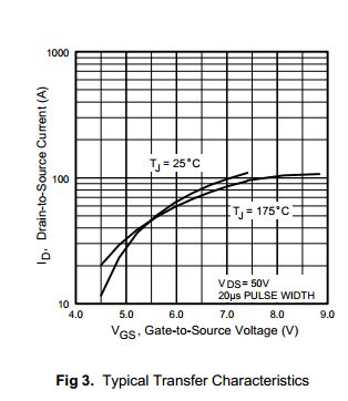
    If you look at the datasheet for the FET you will see that the Vgs threshold is specified as 2.0 to 4.0 V, amd the Transfer characteristic is 

    With the MSP430 powered from 3.3V this FET will noyt switch ON fully.

    You need to be looking for a "Logic Level FET". that will turn on fully with a Vgs of 3.3V. A very quick google search indicates that the FQP30N06L may be a better device, as it operates with a lower gate voltage. As the motor is an inductive load you may also need a diode to suppress back emf when the FET switches off.

    Roy

  • thank will look at that 

  • The higher the maximum current of a FET and the lower the ON resistance, the higher (usually) the gate threshold Ugs. Below Ugs, the gate voltage has no effect. Above, Ids begins to rise until minimum resistance (or rather: maximum current) is reached.
    So the FET you picked maybe won't drive any current at all with a gate voltage of 3.3V.

    MOSFET transistors don’t need a free-wheeling diode, as they have one inside by design.

    Don’t have a too-large series resistor. The FET gate actually is a capacitor. So without series resistor, you have a pure capacitive load on the signal pin. But with a too-high resistor, the gate will charge slowly, keeping the FET in an intermediate state (not fully on) for quite some time, significantly increasing the power dissipation on the transistor.

  • ok I can understand some of that I am a nob when it comes to this sort of thing.

    What would you suggest that I use I have it down of how to connected it but not to sure what FET to use your help is very welcome

  • There are many different FETs on the market.
    For our modulated  laser power supply, we used the SPP70N10L. This one has a threshold voltage of 1.2 to 2V. That means on 1.2 to 2V gate voltage, it begins to conduct.

    The FET can drive up to 70A continuous current (170A peak) and reaches an on resistance as low as 10mOhm on 50A - with a gate voltage of 10V. With 3V gate voltage, it will only drive 35A, with an ON resistance of >50mOhm.

    Usually, the higher the maximum current, the higher the required gate voltage to reach it, and the higher the threshold voltage.
    There are FETs with only 1V threshold voltage, but on 3V gate voltage, they will only drive a few 100mA or some A.

    In my datasheet collection, thee is the IRLR6225PbF. It has a threshold voltage of 0.5 to 1.1V (that’s really low) and drives up to 42A continuous current (up to 200A peak) with 3V gate voltage. However, it’s maximum operating voltage is 20V. Don’t ask me where to get it.

    Another one is the IRL540N is another one, with 1-2V threshold and 36(120)A. With 3V gate voltage, it won’t get higher than 13A, with a resistance of 70-125mOhm (depending on junction temperature). Keep an eye on the power dissipation (13A/125mOhm means 21W) - without cooling (plain PCB mounting), the limit would be 2W = 4A.

    It’s not easy to pick the right FET just by the parameters listed on a typical catalogue page. You’ll have to check the datasheet for the details, before you know whether a FET can be used for your application at all (let alone finding the best one).

  • would I be better off using a npn or a pnp then 

  • daniel lyall said:
    would I be better off using a npn or a pnp then 

    Well, this surely is an option. For smaller loads, I use the ULN2003, which is an array of 7 NPN transistors with free-wheeling diodes and TTL-compatible control inputs. Great for driving a relay. Each transistor can drive as much as 100mA. You can as well put some of them in parallel, if a bit more is required (don’t expect full 100% scaling)

    However, the advantage of using the proper FET is to have a very low voltage drop (and therefore power dissipation) on the transistor and maximum voltage and power on the device you drive.
    Also, for bipolar transistors, you’ll still require the pick the ‘right’ one. These are current-driven, so the base current controls the output current by a fixed factor. The MSP must provide this current.

  • Jens-Michael Gross said:
    the advantage of using the proper FET is to have a very low voltage drop (and therefore power dissipation)

    That' s why FET is my preferred load switch. Let' s assume we need low side continuous 5V 2A switch. Today I would select SOT-23 (!), 3A N-MOSFET SI2302 0.15$. Bipolar alternative that does not melt from 2A will be bigger, dissipate hellova heat, need more PCB footprint for bigger case and heat dissipation and cost more either.

  • so I would need one that can handle 5V and 1A to be safe, each servo actuator will have its own control wire so I will just have to make up a power supply to run the board and the fet, the servo will have its own supply its only 2 batters so wont take up much room they can be modeled in to the arms

**Attention** This is a public forum