This thread has been locked.

If you have a related question, please click the "Ask a related question" button in the top right corner. The newly created question will be automatically linked to this question.

MSP430FG4618 programming

Other Parts Discussed in Thread: MSP430FG4618

I  have two questions..

 1.Is there any way to generate three analog signals (1 Triangle and  2 sinusoidal wave forms  180 degree out phase) .... I need to perform comparison of each of the sinusoidal wave with triangular wave..

2.how to configure op amp as inverter and what is the input to its negetive terminal

  • Lohith,

    the MSP430FG4618 has a built-in 12 bit digital to analog converter which can be used to generate the desired output signals. You could create a look up table for your signals and use a timer that sets the output of the DAC according to the values located in this lookup table. The user's guide

    in chapter 31 (page 869) describes the use of the DAC12.

    When using the internal operational amplifier you can choose which input is the negative or the positive one. You set this in the OAxCTL0 register. The OPAMP is described in chapter 22 (page 647) in the user's guide.

    For both modules there are some code examples you can start with:

    Dennis

  • You can't have three analog outputs simultaneously with the DAC. However, for a sine wave of a fixed frequency, you can use a PWM output and an nth order low-pass filter. The PWM generates a rectangle signal of the desired frequency, and the filter cut's off the overtones, leaving a sinus. (the steeper the filter, the better the sinus)

    For the triangle, the DAC is the best (and easiest) way. Simply step the output up and down with the required speed.

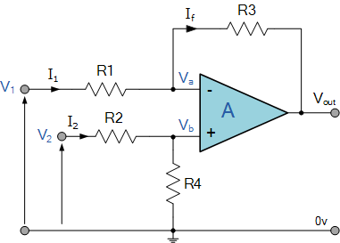
    To use an OpAmp for inverting an analog signal, you need to attach the maximum signal value to the positive (V2) and the signal itself to the negative (V1) side, subtracting it. You need unity gain, so all four resistors are identical.

    Using the typical inverter circuit instead (+ tied to GND), it will literally invert the input voltage, meaning where the input is peak, the output is negative. (mirrored on GND). Which the internal OpAmp of the MSP can't do, as it requires a symmetrical supply. Hence the addition of the peak value as offset.

    You may extract the peak value from the signal itself using a diode and a capacitor as simple peak detector. Provided that your signal is low-impedance enough.

    I'm not sure whether you can configure the internal OpAmp this way without external circuitry.

**Attention** This is a public forum