This thread has been locked.

If you have a related question, please click the "Ask a related question" button in the top right corner. The newly created question will be automatically linked to this question.

Selecting input for ADC for MSP430G2231

Other Parts Discussed in Thread: MSP430G2231

If I want to use pin 9 as the ADC input, which of the following do I need to do?

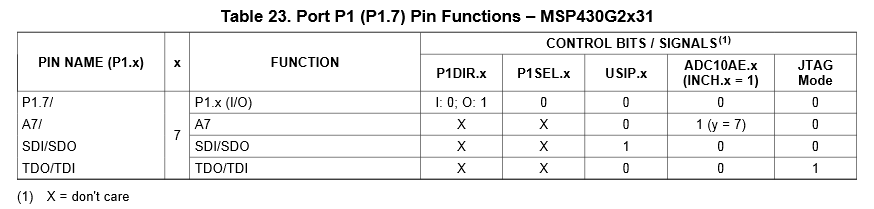
1. Select 0111 for INCHx in ADC10CTL1

2. Set bit 7 in ADC10AE0

3. Set bit 7 in P1SEL

I assume the first two, but in sample code I usually don't see the third.  But maybe that's because it's assumed that's done elsewhere, or maybe it's because doing the second one means the P1SEL value doesn't matter.  Anyway, I would appreciate clarification on this.

  • Pin 9 is typcially called P1.7.

    As you can see on page 43 of the datasheet, P1SEL does not matter for the ADC; you need only ADC10AE and INCH.

  • Hi George,

    Pin 9 of the MSP430G2231 is A7, so selecting 0111 for INCH in ADC10CTL1 is correct.

    There is a definition in the processor's header file for that. It is INCH_7.

    Setting 0x40 (bit 7) in ADC10AE0 enables the analog functionality of P1.7, so you are right again.

    The P1SEL register selects the special function of the appropriate pin. To see the required configuration, open the datasheet:

    On page 43 it gives you the following table:

    Look at the second line for using this pin as A7 - it says Don't Care for P1DIR and Don't Care for P1SEL, so you can either write something into the register for this bit or leave it. It makes no difference. That's why you don't see it in the sample code. But the table also says that you have to enable this bit in ADC10AE which you have noticed yourself.

    Dennis

  • Yes, there is was, right in front of me. Thanks very much.
  • George!

    Just saw a mistake! Sorry for that!
    "Setting 0x40 (bit 7) in ADC10AE0" is wrong, of course. Bit 7 is 0x80!

    Dennis

**Attention** This is a public forum