This thread has been locked.

If you have a related question, please click the "Ask a related question" button in the top right corner. The newly created question will be automatically linked to this question.

MSP432Launchpad Uart Delay

Other Parts Discussed in Thread: MSP430F5529, MSPWARE, MAX232

Dear TI Community,

I am in trouble with MSP-EXP432P401R Launchpad UART module. I am trying to evaluate the boar uart capabilities with the DriverLib example:uart_pc_echo_12mhz_brclk. Uploaded the example code to the device and created a host program with LabVIEW. To keep everything simple, on MSP side I have not made any modification on the example code. In LabVIEW using Example finder with keywords "Serial" the vi named: "Basic Serial Write and Read.vi" you can find the host VI for test.

My problem is: The elapsed time between sending a byte to the MSP UART and receiving a byte takes too long. In the above example, it takes 150 ms to get a reply from MSP432. 

I have tried the following:

  • Changing the USB ports (type 2.0 | type 3.0) 
  • MCLK speed, UART speed, 

without any success.

Anyway, it takes 150ms to get a first character from the MSP. If I sending back more bytes to the host, the speed is OK.

Could you help me to handle this issue? Thank you so much!

Basic Serial Write and Read.rar

  • > takes 150ms to get a first character

    Could be a fifo buffer problem in the chain somewhere. 
    Maybe it's the virtual com port that tries to buffer chars if possible, but gives up on waiting for more chars after 150ms
    Same way TCP try's to send chunks if possible.

  • Hey,

    Thank you for your reply. Same delay when i send multibyte instead of one. Using F5529 launchpad it works flawlessly. I hope we will sution for this.

  • Its important to mention. When I send more data to host, i have to wait 150ms to get the first byte. The rest of data chunk comes without delay. So every time the first byte arrives in late.

    Update: I have tried the same on a different laptop and I got same result. :(

  • I've been doing a lot of serial stuff with the msp432 and it seems to work just fine. Searching around about the Labview thing returned lots of reasons why the labview stuff might be your problem:

    forums.ni.com/.../901654

    Try searching google with this search term:

    labview serial port delay "Basic Serial Write and Read.vi"
  • Hey Rick,

    Thank you for your reply, it was really helpful. I am going to write a similar application in C# to test the communication and share the result here. By the way, I am worried about this delay issue. I have used MSP430F5529 Launchpad several times in high throughput DAQ applications and I have never realized similar behavior like that.

    Unfortunately, I need to change my MSP432 hardware to MSP430 in this application :(((

    If any of you experienced delay with MSP432 + LabVIEW combo, please send me a message.
    Of course any reply from TI support are welcome!
  • Hey Rick,

    I tested the MSP432 with C# serial host, and I can definitely tell you this is not a LabVIEW issue. I can measure the same amount of delay with C# host. With both hosts for MSP430F5529 USB examples there is no delay and works like a charm. 

        Stopwatch sw = new Stopwatch();
                
                SerialPort sp = new SerialPort("COM41", 9600, Parity.None, 8, StopBits.One);
                char[] reply = new char[10];
                
                sp.Open();
    
                sw.Start();
    
                sp.Write("a");
                sp.Read(reply, 0, 1);
                sw.Stop();
    
                Debug.WriteLine("Elapsed Time: " + sw.ElapsedMilliseconds.ToString());
    
                sp.Close();
    
                Console.ReadLine();

    Is there anyone else here, who could spend 10 minutes on testing his MSP432P401R Launchpad with the MSPWare uart_pc_echo_12mhz_brclk example? Thank you guys,

  • Hi,

    Is there any chance to get an answer to my queston? If not,  do you suggest a forum where I can? Thank you

  • It seems like this is the right forum. I'm not sure how you get an answer out of TI proper other than posting here or asking a Field Rep.

    I'm not using windows so any thing I might find is only going to be related to linux. To be honest, I have a pile of FTDI dongles I use when I want to do serial communications.

  • Hey Rick,
    You are my only hope, thank you for posting.

    No problem with linux. I would be grateful if u could try it. Well I could know it is an msp issue or os issue. Any test an result would be very kind from you.

    I do really love this board,but I am very disappointed.
  • Evening, 

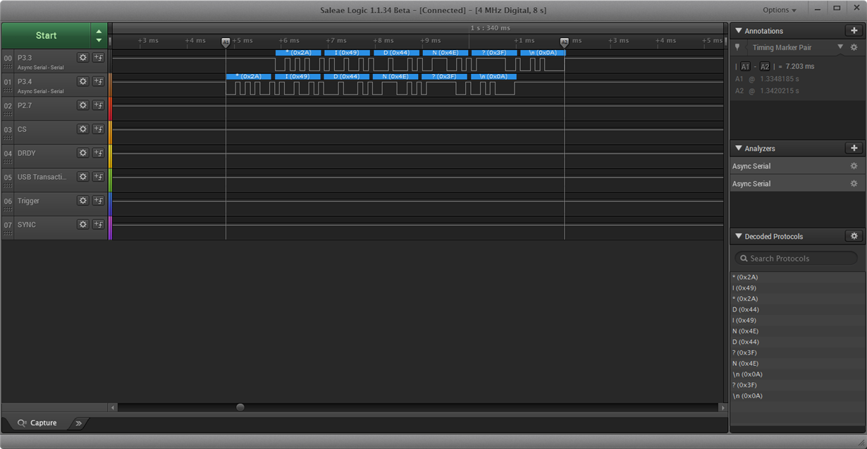
    Well, I have some news about this issue. Here is a screenshot about the MSP432 echo example. 

    Everything is working flawlessly on MSP. Fast and accurate.

    Wll, only a few question remains: Why does it take 100ms time for the Host PC to recognize the incoming data? And why does the MSP430F5529 USB solution much more faster? How can I make the host to read the incoming data more faster?

  • Daniel Vamos said:
    How can I make the host to read the incoming data more faster?

    You can use a dedicated USB/Serial bridge ic (FTDI or similar) as this may have better drivers.

    Or you can try flushing the data through the buffers using NULL postamble. 50 to 200 characters should work.

    The problematic buffer may be on one or both data directions.

    Peter

  • Dear Peter,

    Thank you very much for your kind reply. 

    "You can use a dedicated USB/Serial bridge ic (FTDI or similar) as this may have better drivers." -  I am afraid but I don't really understand you. I am not an expert in serial ICs. On the launchpad I have XDS110-ET. I think this device is responsible for communication back to PC. On the PC side I have numerous usb A sockets. How can I try different vendor chipset?

     "Or you can try flushing the data through the buffers using NULL postamble. 50 to 200 characters should work." - I have never done this before. You mean I send 50-200 '\0' character from MSP to PC via UART? 

    Yesterday I played a bit wit MSP and can measure vary time delay between Serial Write and Read. Sometime it takes about 100ms to read a character from MSP but sometimes 5-10ms was sufficient to get a valid read.

    Sorry for my noob questions ;) 

  • hello, I'm sending your question to the experts at Texas Instruments, hopefully give you a quick solution!

    I'm aware of how difficult it is to program in CCS
  • Daniel,

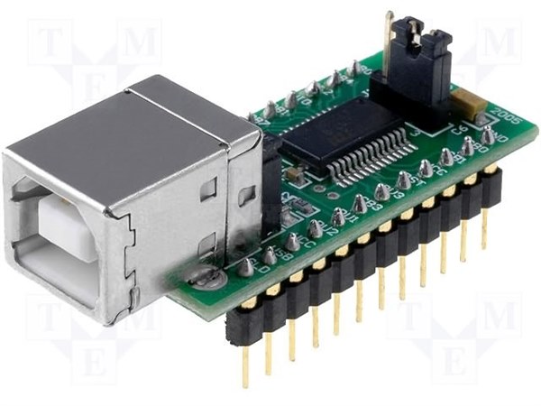
    If you want to test another USB<->UART bridge you could try the popular FT232 from FTDI.

    There is a breadboard adapter for it, the UM232:

    Or you could even use the MAX232 if you still have one of the older RS232 connectors on your PC.

    Just connect it to an USCI A module of the LaunchPad and don't use the emulated UART on the board.

    Dennis

  • wow, the response was quick :)
  • Dear Martin,
    Thank you for your quick reply. I saw your blog entry so I suppose you have already worked with MSP432 uart. Did you noticed any delay between sending and receiving bytes via UART?

    I am using the MSPWare example 12MHZ UART loopback and a simple time measurement on PC host. The measured time is always in range btw 10ms - 150ms. Do you have any performance info?

    Due to this large latency I can not use this board for high speed and time depended applications like ADC purposes.
  • Dear Dennis,

    Thank you for your time and your answer. This should be fine for test purposes but if it is possible I don't want to involve extra hardware to my system. The simple is the best.

    I am going to order this device and see the latency if there is.

    Lets suppose the delay is no more with FT232, well I could only use this UART for low speed applications?

    PS: I have reinstalled the XDS110 Driver but nothing changed.
  • Daniel,

    Change your code like the following:
    Set an output pin from low to high when just received your character from the PC into your receive buffer and set it back to low again when the controller writes the answer data byte into the transmit buffer. Then measure the time of the high signal on an oscilloscope. Then you can see if it is the micro or the UART bridge / PC that causes the delay.

    What else is your micro doing? Or just the example code? Could you upload your code in something else than a .rar file?

    Dennis

  • By the way: Are there bytes missing or are all completely sent, but with the delay?
  • Here is the attachment: 

    • LabVIEW serial host program where I measure the delay between Serial Write and Read. (Using this labVIEW code with msp430F5529 USB example, this time is about 1-2 ms)
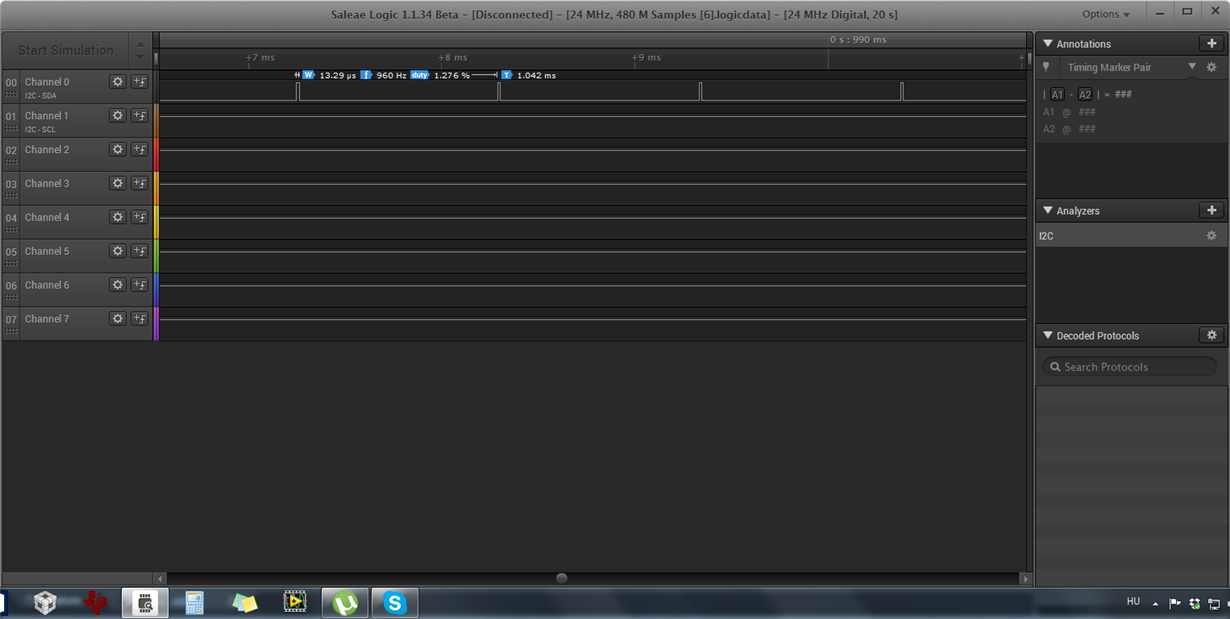
    • Saleae export data, where you can see the micro is working well
    • CCS project that I used for testing.

    TI Forum.rar

  • That is .rar again - I cannot open it without download another 3rd party software.
  • Daniel, just had a quick look into the code and I am wondering about MSB first when using 232/UART. So what are you detecting? Just any byte or do you check the data for a special pattern? And agian: Are bytes lost or do they come delayed, but completely?

    Dennis
  • When I send a byte or bytes to MSP from LabVIEW (see and use attached vi) and wait for any reply, it takes 150ms to get the first byte. All the remaining bytes arrive completely. There is no data loss in communication only a large latency.

    I have also observed that, when I send a byte from LabVIEW host to MSP it takes long to get the first byte back to LabVIEW again. All the remaining bytes arrives less than a millisecond. (If I send more data from MSP of course.)

    If you have LabVIEW installed you can try.

    (The C code is come from DriverLib I have added only the LED toggling statements. No other code modified.)

  • Sorry, I cannot try the LabVIEW site, I don't have it.
  • No problem. I have tested with C# serial host but the issue is still exists.
    But I don't have the C# code on this laptop. :( 4-5 hours later I can send it to you if u need.
  • If you need any information that should help you to reveal the problem, let me know. I will do my best!
  • Daniel, could you try a simple terminal program like hterm to send and receive data? Without LabVIEW? And see if the delay is still present?
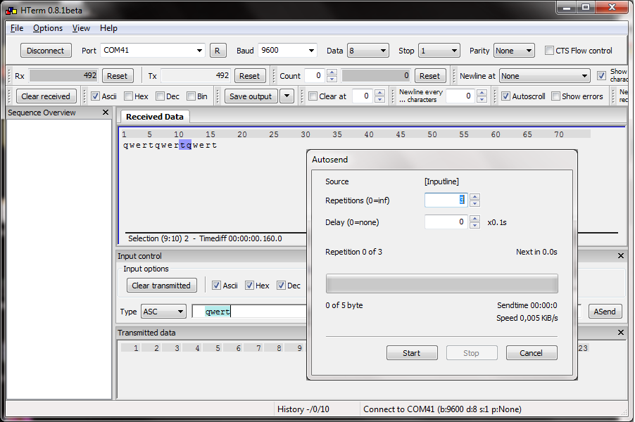
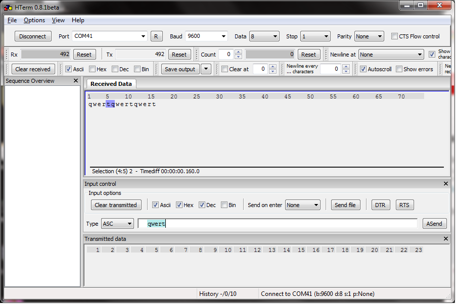
  • No problem. Here is a screenshot:

    Char series that I send is "qwert" . You can see the result: and the 160 ms delay between repeated cycles.

  • An PC hardware RS232 port is interrupt driven and the PC will react immediately on the reception of a character.
    A virtual USB COM port is not interrupt driven but scheduled by the task manager.
    Characters will be received in packages and the buffer is polled for the state.
    Depending on the PC driver used, the polling time and buffer size can be adjusted in the Device Manager.

    Depending on PC hardware, a change on the RS232 status lines, CTS/DSR/DCD or RI, can trigger a data transfer.
  • Then you now know it is not a LabVIEW thing. I would guess it is the driver, too, which means I agree with Leo.
    Unfortunately there isn't much to adjust within the drivers. You can move some bars that set the buffer size for example, but that is almost everything. So try another bridge or switch over to the real RS232 if you have one. Then you can use higher baudrates, too.
  • I have changed the Clock speed and the baud rates too. Nothing changed.  If you say the problem is my usb driver in my laptop and all of my 3 pc-s I am very very sad. It wont be easy to find a right platform for MSP432.

    "virtual USB COM port is not interrupt driven but scheduled by the task manager." - According to this explanation the Interrupt driven should be more faster than the scheduled. So why does the MSP430F5529 USB example performs faster communication than the MSP432 uart? Basically Mr. Leo answer is right but I think it is not relevant in my case.

    What about the XDS110-ET driver?  Do you think is it working properly? Is there any driver release note or update?

    I do really love this MSP432 and I would like to use numerous applications.  But this delay is NOT acceptable for me.

    May I ask you to make some test at your office or lab focusing on this issue that I reported? Am I the only one who realized this delay?

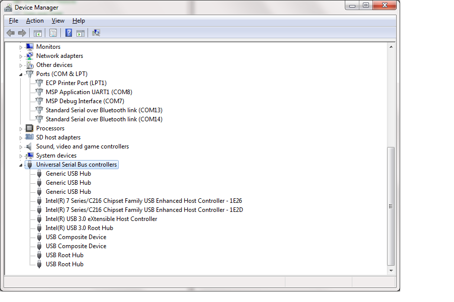
    I am not giving up trying to find out what is behind. My primary laptop is Dell Latitude E5530 | OS is Win7 64Bit. And below you can see my usb controllers.

    BTW, a cost of an FTDI -USB/UART converter is around the cost of MSP432 :(

  • Hi Daniel,
    I couldn't read your logic analyzer output, but from the conversation I assume that the latency on the MSP432 device itself between receiving the first byte and sending out the byte in response is much less than 150ms?

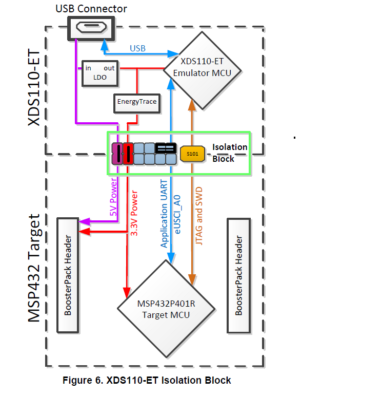
    Another quick experiment to confirm that the latency can be attributed to the back-channel UART bridge on the XDS110-ET (the on-board debugger of the MSP432 LaunchPad) is to simply flip the RXD & TXD jumpers on the LaunchPad by 90 degrees. You can essentially create a hard-wired UART loop-back for the XDS110-ET itself and eliminate the MSP432 MCU dependency.

    If it still takes ~150ms from when you send a character until you receive the loop-back charater in Hterm or LabView, we know it's 100% related to the XDS110-ET.

    ~Dung
  • Daniel,

    I made some tests - here is the code I used:

    //*****************************************************************************
    //
    // Test: Echo back received UART characters
    //
    //****************************************************************************
    
    #include "msp432p401r.h"
    
    void main( void )
    {
      WDTCTL = WDTPW | WDTHOLD;                    // Stop watchdog timer
    
      CSKEY = 0x695A;                              // Unlock CS module for register access
      CSCTL0 = 0;                                  // Reset tuning parameters
      CSCTL0 = DCORSEL_3;                          // Set DCO to 12MHz (nominal, center of 8-16MHz range)
                                                   // Select ACLK = REFO, SMCLK = MCLK = DCO
      CSCTL1 = SELA_2 | SELS_3 | SELM_3;
      CSKEY = 0;                                   // Lock CS module from unintended accesses
    
      // Configure UART pins
      P1SEL0 |= BIT2 | BIT3;                       // set 2-UART pin as second function
    
      __enable_interrupt();
      NVIC_ISER0 = 1 << ((INT_EUSCIA0 - 16) & 31); // Enable eUSCIA0 interrupt in NVIC module
    
      // Configure UART
      UCA0CTLW0 |= UCSWRST;
      UCA0CTLW0 |= UCSSEL__SMCLK;                  // Put eUSCI in reset
      // Baud Rate calculation
      // 12000000/(16*9600) = 78.125
      // Fractional portion = 0.125
      // User's Guide Table 21-4: UCBRSx = 0x10
      // UCBRFx = int ( (78.125-78)*16) = 2
      UCA0BR0 = 78;                                // 12000000/16/9600
      UCA0BR1 = 0x00;
      UCA0MCTLW = 0x1000 | UCOS16 | 0x0020;
    
      UCA0CTLW0 &= ~UCSWRST;                       // Initialize eUSCI
      UCA0IE |= UCRXIE;                            // Enable USCI_A0 RX interrupt
    
      while( 1 );
    }
    
    // UART interrupt service routine
    void eUSCIA0IsrHandler( void )
    {
      if( UCA0IFG & UCRXIFG )
      {
        while( !(UCA0IFG & UCTXIFG) );
        UCA0TXBUF = UCA0RXBUF;
      }
    }

    msp432_startup_ccs.c
    //*****************************************************************************
    //
    // Copyright (C) 2012 - 2014 Texas Instruments Incorporated - http://www.ti.com/
    //
    // Redistribution and use in source and binary forms, with or without
    // modification, are permitted provided that the following conditions
    // are met:
    //
    //  Redistributions of source code must retain the above copyright
    //  notice, this list of conditions and the following disclaimer.
    //
    //  Redistributions in binary form must reproduce the above copyright
    //  notice, this list of conditions and the following disclaimer in the
    //  documentation and/or other materials provided with the
    //  distribution.
    //
    //  Neither the name of Texas Instruments Incorporated nor the names of
    //  its contributors may be used to endorse or promote products derived
    //  from this software without specific prior written permission.
    //
    // THIS SOFTWARE IS PROVIDED BY THE COPYRIGHT HOLDERS AND CONTRIBUTORS
    // "AS IS" AND ANY EXPRESS OR IMPLIED WARRANTIES, INCLUDING, BUT NOT
    // LIMITED TO, THE IMPLIED WARRANTIES OF MERCHANTABILITY AND FITNESS FOR
    // A PARTICULAR PURPOSE ARE DISCLAIMED. IN NO EVENT SHALL THE COPYRIGHT
    // OWNER OR CONTRIBUTORS BE LIABLE FOR ANY DIRECT, INDIRECT, INCIDENTAL,
    // SPECIAL, EXEMPLARY, OR CONSEQUENTIAL DAMAGES (INCLUDING, BUT NOT
    // LIMITED TO, PROCUREMENT OF SUBSTITUTE GOODS OR SERVICES; LOSS OF USE,
    // DATA, OR PROFITS; OR BUSINESS INTERRUPTION) HOWEVER CAUSED AND ON ANY
    // THEORY OF LIABILITY, WHETHER IN CONTRACT, STRICT LIABILITY, OR TORT
    // (INCLUDING NEGLIGENCE OR OTHERWISE) ARISING IN ANY WAY OUT OF THE USE
    // OF THIS SOFTWARE, EVEN IF ADVISED OF THE POSSIBILITY OF SUCH DAMAGE.
    //
    // MSP432 Family Interrupt Vector Table for CGT
    //
    //****************************************************************************
    
    #include <stdint.h>
    
    /* Forward declaration of the default fault handlers. */
    static void resetISR(void);
    static void nmiISR(void);
    static void faultISR(void);
    static void defaultISR(void);
    
    
    /* External declaration for the reset handler that is to be called when the */
    /* processor is started                                                     */
    extern void _c_int00(void);
    
    
    /* Linker variable that marks the top of the stack. */
    extern unsigned long __STACK_END;
    
    
    /* External declarations for the interrupt handlers used by the application. */
    extern void eUSCIA0IsrHandler( void );
    /* To be added by user */
    
    
    /* Intrrupt vector table.  Note that the proper constructs must be placed on this to  */
    /* ensure that it ends up at physical address 0x0000.0000 or at the start of          */
    /* the program if located at a start address other than 0.                            */
    #pragma DATA_SECTION(interruptVectors, ".intvecs")
    void (* const interruptVectors[])(void) =
    {
        (void (*)(void))((uint32_t)&__STACK_END),
                                                /* The initial stack pointer */
        resetISR,                               /* The reset handler         */
        nmiISR,                                 /* The NMI handler           */
        faultISR,                               /* The hard fault handler    */
        defaultISR,                             /* The MPU fault handler     */
        defaultISR,                             /* The bus fault handler     */
        defaultISR,                             /* The usage fault handler   */
        0,                                      /* Reserved                  */
        0,                                      /* Reserved                  */
        0,                                      /* Reserved                  */
        0,                                      /* Reserved                  */
        defaultISR,                             /* SVCall handler            */
        defaultISR,                             /* Debug monitor handler     */
        0,                                      /* Reserved                  */
        defaultISR,                             /* The PendSV handler        */
        defaultISR,                             /* The SysTick handler       */
        defaultISR,                             /* PSS ISR                   */
        defaultISR,                             /* CS ISR                    */
        defaultISR,                             /* PCM ISR                   */
        defaultISR,                             /* WDT ISR                   */
        defaultISR,                             /* FPU ISR                   */
        defaultISR,                             /* FLCTL ISR                 */
        defaultISR,                             /* COMP0 ISR                 */
        defaultISR,                             /* COMP1 ISR                 */
        defaultISR,                             /* TA0_0 ISR                 */
        defaultISR,                             /* TA0_N ISR                 */
        defaultISR,                             /* TA1_0 ISR                 */
        defaultISR,                             /* TA1_N ISR                 */
        defaultISR,                             /* TA2_0 ISR                 */
        defaultISR,                             /* TA2_N ISR                 */
        defaultISR,                             /* TA3_0 ISR                 */
        defaultISR,                             /* TA3_N ISR                 */
    	eUSCIA0IsrHandler,                      /* EUSCIA0 ISR               */
        defaultISR,                             /* EUSCIA1 ISR               */
        defaultISR,                             /* EUSCIA2 ISR               */
        defaultISR,                             /* EUSCIA3 ISR               */
        defaultISR,                             /* EUSCIB0 ISR               */
        defaultISR,                             /* EUSCIB1 ISR               */
        defaultISR,                             /* EUSCIB2 ISR               */
        defaultISR,                             /* EUSCIB3 ISR               */
        defaultISR,                             /* ADC14 ISR                 */
        defaultISR,                             /* T32_INT1 ISR              */
        defaultISR,                             /* T32_INT2 ISR              */
        defaultISR,                             /* T32_INTC ISR              */
        defaultISR,                             /* AES ISR                   */
        defaultISR,                             /* RTC ISR                   */
        defaultISR,                             /* DMA_ERR ISR               */
        defaultISR,                             /* DMA_INT3 ISR              */
        defaultISR,                             /* DMA_INT2 ISR              */
        defaultISR,                             /* DMA_INT1 ISR              */
        defaultISR,                             /* DMA_INT0 ISR              */
        defaultISR,                             /* PORT1 ISR                 */
        defaultISR,                             /* PORT2 ISR                 */
        defaultISR,                             /* PORT3 ISR                 */
        defaultISR,                             /* PORT4 ISR                 */
        defaultISR,                             /* PORT5 ISR                 */
        defaultISR,                             /* PORT6 ISR                 */
        defaultISR,                             /* Reserved 41               */
        defaultISR,                             /* Reserved 42               */
        defaultISR,                             /* Reserved 43               */
        defaultISR,                             /* Reserved 44               */
        defaultISR,                             /* Reserved 45               */
        defaultISR,                             /* Reserved 46               */
        defaultISR,                             /* Reserved 47               */
        defaultISR,                             /* Reserved 48               */
        defaultISR,                             /* Reserved 49               */
        defaultISR,                             /* Reserved 50               */
        defaultISR,                             /* Reserved 51               */
        defaultISR,                             /* Reserved 52               */
        defaultISR,                             /* Reserved 53               */
        defaultISR,                             /* Reserved 54               */
        defaultISR,                             /* Reserved 55               */
        defaultISR,                             /* Reserved 56               */
        defaultISR,                             /* Reserved 57               */
        defaultISR,                             /* Reserved 58               */
        defaultISR,                             /* Reserved 59               */
        defaultISR,                             /* Reserved 60               */
        defaultISR,                             /* Reserved 61               */
        defaultISR,                             /* Reserved 62               */
        defaultISR,                             /* Reserved 63               */
        defaultISR                              /* Reserved 64               */
    };
    
    
    /* This is the code that gets called when the processor first starts execution */
    /* following a reset event.  Only the absolutely necessary set is performed,   */
    /* after which the application supplied entry() routine is called.  Any fancy  */
    /* actions (such as making decisions based on the reset cause register, and    */
    /* resetting the bits in that register) are left solely in the hands of the    */
    /* application.                                                                */
    void resetISR(void)
    {
        /* Jump to the CCS C Initialization Routine. */
        __asm("    .global _c_int00\n"
              "    b.w     _c_int00");
    }
    
    
    /* This is the code that gets called when the processor receives a NMI.  This  */
    /* simply enters an infinite loop, preserving the system state for examination */
    /* by a debugger.                                                              */
    static void nmiISR(void)
    {
        /* Fault trap exempt from ULP advisor */
        #pragma diag_push
        #pragma CHECK_ULP("-2.1")
    
        /* Enter an infinite loop. */
        while(1)
        {
        }
    
        #pragma diag_pop
    }
    
    
    /* This is the code that gets called when the processor receives a fault        */
    /* interrupt.  This simply enters an infinite loop, preserving the system state */
    /* for examination by a debugger.                                               */
    static void faultISR(void)
    {
        /* Fault trap exempt from ULP advisor */
        #pragma diag_push
        #pragma CHECK_ULP("-2.1")
    
        /* Enter an infinite loop. */
        while(1)
        {
        }
    
        #pragma diag_pop
    }
    
    
    /* This is the code that gets called when the processor receives an unexpected  */
    /* interrupt.  This simply enters an infinite loop, preserving the system state */
    /* for examination by a debugger.                                               */
    static void defaultISR(void)
    {
        /* Fault trap exempt from ULP advisor */
        #pragma diag_push
        #pragma CHECK_ULP("-2.1")
    
        /* Enter an infinite loop. */
        while(1)
        {
        }
    
        #pragma diag_pop
    }
    

    And then I sent the character "T" ten times in a row and I configured the terminal program to enter a new line after a receive pause of more than 10ms - here is the output:

    17:15:29.306:
    T
    17:15:29.463:
    T
    17:15:29.634:
    TT
    17:15:29.791:
    T
    17:15:29.947:
    TT
    17:15:30.103:
    T
    17:15:30.275:
    TT

    As you can see sometimes only one character is fetched and sometimes there are two. This looks like your delay is based on the application UART because the data seems to be polled.

    I would recommend my erlier suggestion: Look at the high-time of a port-pin that tells you the time between receiving and sending. This one doesn't lie.


    Dennis

  • Daniel,

    tomorrow I can test the same thing with an UM232 if you want. I got some of them.

    Dennis
  • Dear Dung,

    I will do the test tonight, thank you for this great idea!
  • Dear Dennis,

    As I understand you have implemented another echo application on MSP432. Your result and Dung Dang are pointing at the same:  The problem seems to be the XDS110-ET itself?

    "I would recommend my erlier suggestion: Look at the high-time of a port-pin that tells you the time between receiving and sending. This one doesn't lie."  - When I did this trial it was clear to me that the UART receive and transmit operations were fast enough.

    as you can see the attached image:

    The high time is about 15us. For continuously incoming data (4bytes) time delay is 1ms. That is the speed that I expect from 9600 Baud rate. I have measured on LED1 pin as you suggested in your prev. post.

    I am very curious about the UM232 outcome. This way you eliminate the presence of XDS110-ET, hence I am expecting 0-1ms delay. 

    Thank you for your help!

  • No problem! I will report.

    Dennis
  • Hey,

    On the picture below you can see the jumper configuration. In this way, I can still measure the ~150ms delay on the Serial Host side. 

    Finally we can say that, the XDS110-ET is the problem. I am very disappointed, because I don't see any way how can I make it work. 

    Dennis will report his result tomorrow.

  • Daniel,

    Can you send a 200 byte data payload to your loopback setup.

    I expect that the first byte will return within 50 ms.

    Peter

  • Hello Peter,

    I have tried your suggestion, sending 200 and more bytes to loopback. You are right, the first byte arrives faster, about 100ms. But if I want to read back the whole data in loopback setup, the communication time takes 360ms!

    :(
  • Daniel,

    I tried it now and I have bad news for you: The delay is about 110ms.

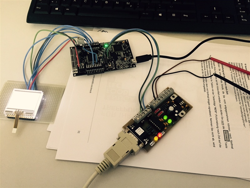
    Here is the UM232 connected to the LaunchPad:

    Don't worry about the LCD, it is my actual project. But it is dead while running your code.

    This is the output:

    06:33:25.790:
    T
    06:33:25.899:
    T
    06:33:26.008:
    T
    06:33:26.118:
    T
    06:33:26.243:
    T
    06:33:26.352:
    T
    06:33:26.461:
    T
    06:33:26.555:
    T
    06:33:26.665:
    T
    06:33:26.774:
    T
    06:33:26.899:
    T
    06:33:27.008:
    T
    06:33:27.118:
    T
    06:33:27.212:
    T
    06:33:27.321:
    T
    06:33:27.430:
    T
    06:33:27.540:
    T
    06:33:27.665:
    T
    06:33:27.774:
    T
    06:33:27.883:
    T
    06:33:27.977:
    T
    06:33:28.087:
    T
    06:33:28.196:
    T
    06:33:28.321:
    T
    06:33:28.430:
    T
    06:33:28.524:
    T
    06:33:28.633:
    T
    06:33:28.743:
    T
    06:33:28.852:
    T
    06:33:28.977:
    T

    Now there is only the hardware genuine RS232 left.

    Dennis

  • So this is now the point where I start to think that it is the terminal itself that is polling the data too slowly. Look, this is bare hardware now, the real RS232 connected to the DB9 serial port:

    And this is the output:

    07:02:44.301:
    T
    07:02:44.414:
    T
    07:02:44.523:
    T
    07:02:44.629:
    T
    07:02:44.744:
    T
    07:02:44.852:
    T
    07:02:44.956:
    T
    07:02:45.068:
    T
    07:02:45.176:
    T
    07:02:45.288:
    T

    It is about 100ms, too.

    Dennis

  • If you disable the buffer for the RS232:

    You still have the delay of ~100ms:

    07:14:30.354:
    T
    07:14:30.463:
    T
    07:14:30.570:
    T
    07:14:30.675:
    T
    07:14:30.787:
    T
    07:14:30.899:
    T
    07:14:31.008:
    T
    07:14:31.112:
    T
    07:14:31.225:
    T
    07:14:31.333:
    T

    This is when you connect pin 2 and 3 of the DB9 connector (no MSP):

    07:19:06.371:
    T
    07:19:06.482:
    T
    07:19:06.593:
    T
    07:19:06.697:
    T
    07:19:06.809:
    T
    07:19:06.919:
    T
    07:19:07.027:
    T
    07:19:07.139:
    T
    07:19:07.247:
    T
    07:19:07.355:
    T

    Still the same of course. So now you could check if the data is maybe sent in 100ms delays and therefore received with that delay, too.

    Dennis

  • And there it is! (Hardware RS232: pin on the DB9 connector is measured)

    This is the data byte - you can see that one bit time is about 9.6kHz, which is 9600 baud:

    And now...be excited:

    The data is sent with a delay of 110ms between each data byte. So there will be a delay of the same time when receiving it.

    Sending of the bytes is the problem, not receiving. So maybe all our deliberations are obsolete.

    I don't know if it is the RS232 hardware driver or the program that causes the delay.

    Now we could test the MSP432 sending bytes on and on to the PC and have a look at the time difference between each byte.

    Dennis

  • Daniel,

    look:

    Here the LaunchPad sends data in a loop - as you can see there is a time difference of 100ms between byte 0 and 96.

    By the way: The next measureable step is another 100ms, so this isn't really reliable.

    BUT: This is the XDS110 application UART

    So there is no problem with the driver of it. , you can relax again :)

    It is all about the sending of the data.

    Dennis

  • Dear Dennis,

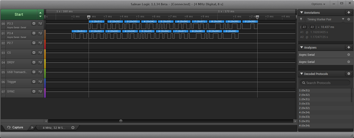
    Thank you for your effort. I have made another interesting test, about sending 10bytes from LabVIEW to MSP and connected a Logic analyzer on the Isolation pins RXD and TXD. and here is the result:

    As you can see sending 10bytes takes only ~10ms. And the MSP sends the received data back to the host. So, I don't sense any problem on the MSP  side.

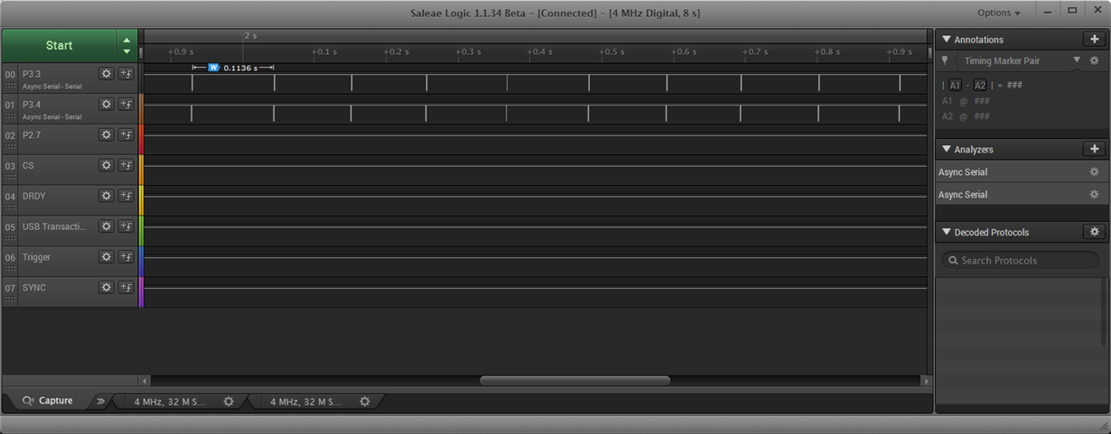
    I have repeated the test using HTerm, and here is the result:

    You can realize a 100ms delay between each send. Well this is HTerm issue. Not MSP.  The MSP is capable of receiving and transmitting data at the most speed without delay.

    I think the problem still is the XDS110ET or its PC side driver itself.

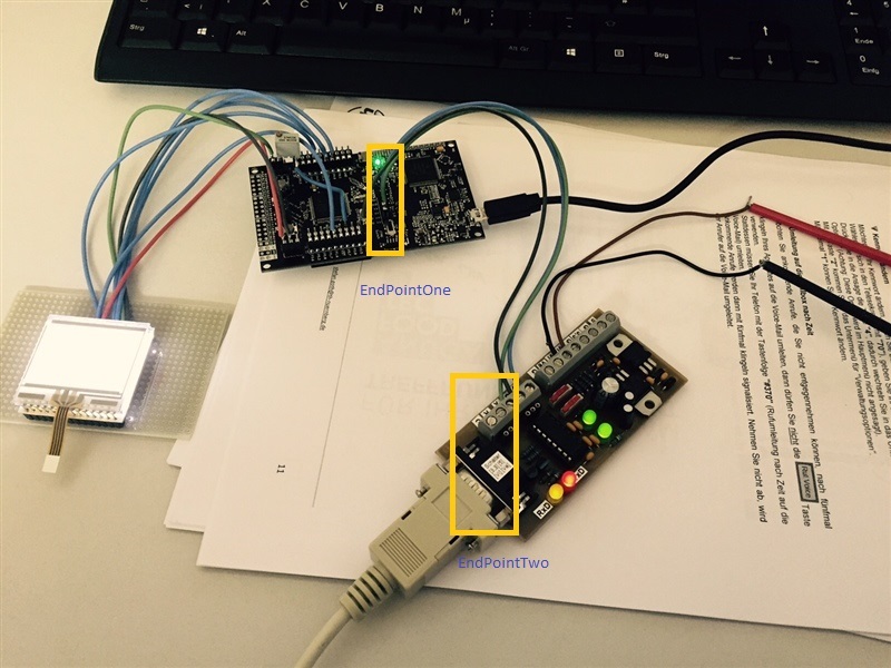
  • I would like to measure the latency between the following two points.

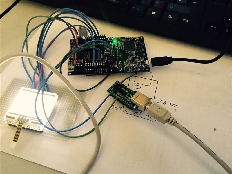
    One endpoint is located on the MSP432 isolation pin RXD or TXD. Another endpoint should be somewhere on your breakout board. See the photo:

    If we measure any delay between the 2 endpoints, the problem is the XDS itself. Anyways it is Driver issue.

    PS.: I have cut micro usb cable and connected the USB wires directly, now I can attach the scope on the wire. Unfortunately, I don't understand the signals that I sense. That why I would like to ask you to select another endpoint.

  • I figured out another thing - there is an issue with HTerm:

    When you use the repeated sending of a pattern, the delay is not present between the single bytes of a pattern, only between the end of the previous sequence and the next one.

    I sent TEST as a repeated sequence. And now only a guess - you can input a delay between each sequence which is always a multiple of 100ms, but if you input 0 there shouldn't be a delay. Maybe there is a software bug that has at least 1 as input.

    Dennis

  • Measuring the USB signal isn't a good idea. You will not only see your data bytes there.
    There won't be a measureable difference between the two points you marked since it is only a short piece of wire. The XDS110 isn't invlolved in this picture.

**Attention** This is a public forum