This thread has been locked.

If you have a related question, please click the "Ask a related question" button in the top right corner. The newly created question will be automatically linked to this question.

MSP430 VDD=3.3, DVIO=1.8V, which level should JTAG/SBW lines be ?

Other Parts Discussed in Thread: MSP430F5259

Hi, 

I would like to program MSP430F5259 that is powered from 3.3V and its I/Os are 1.8V.

  • Is such scenario being handled gracefully by the FET programmer ? what would be the JTAG lines voltage in this case ? Which rail should I tie VCC_TARGET (if any)
  • If using SBW, it is recommended to pull up TEST/SBWTCK line (here, at the end). To which rail ?
  • If I need the PCB powered from VCC_TOOL (pin 2 of the JTAG connector) instead of its battery, it will require 3.6V delivered by the programmer.
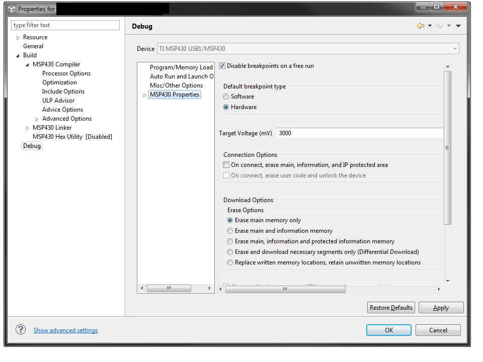
    • How can I 'force' the programmer to output 3.6V ?
    • In this case to what rail should I tie VCC_TARGET ?
    • Will it conflict with the DVIO=1.8V condition ?

Thanks in advance for any support.

  • Hello E L55,

    the JTAG/SBW interface works with DVcc and the FET-Programmer will taking care of the right voltage. The TEST/SBWTCK line has to be pulled up to DVcc.

    Since this device has two Reset-Pins, one for DVcc-Level and one for DVIO-Level, you have to take care to provide the correct level to each of them, but the Reset-Line coming from the JTAG-Interface has to be connected to RSTDVCC (pin 64 on the QFN64 package).

    When you supply the device with the programmer VCC_Target has to be tied to DVcc-Rail. DVIO should be generated by an LDO or you connected it to a dedicated 1.8V rail.

    In Code-Composer-Studio you can change the Programmer-Voltage within the  "Project-Properties --> Debug --> MSP430 Properties" (see attached screen).

    Best regards,

    Michael

**Attention** This is a public forum