This thread has been locked.

If you have a related question, please click the "Ask a related question" button in the top right corner. The newly created question will be automatically linked to this question.

eUSCI in I2C mode responds to itself?

Other Parts Discussed in Thread: MSP430F6779A, MSP430F2618

I am using multimaster I2C to connect a couple of MSP430F6779A's. I have gotten the code to send messages back and forth to work just fine. I wrote a search function to send a message to every device on the bus and see which addresses get ACKed. To my surprise the address of the searching MSP as well as the address of the receiving MSP were ACKed.

I was expecting that the I2C peripheral would not ACK in slave mode packets that it sends in master mode. This was my experience when writing similar code for the MSP430F2618.

When reading the user guide I saw nothing that said one way or another weather interrupts were expected in response to data transmitted by the I2C peripheral or what is expected in this case. Is it possible to NACK the own address programed into the I2C peripheral? is there a way to detect if the peripheral is sending data to itself or should this be checked in the sending code?

  • Hi Jesse,

    Interesting question, could you post your code and I can work on resolving this issue. I will also try to find additional documentation regarding I2C on the MSP430F6779A device.

    Sincerely,
    Sean
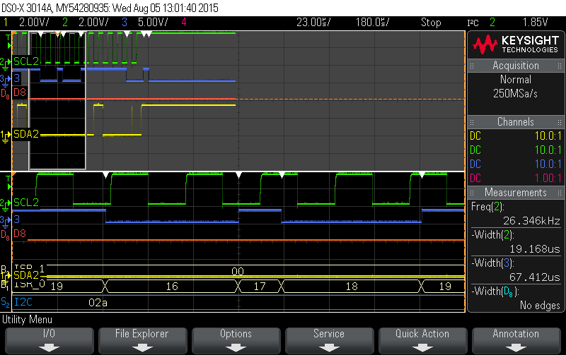
  • Attached is a testcase I wrote. It sends an I2C message every second that should be {1,2,3,4}. When it sends to itself it only sends {1,2,4} because the slave code confuses it. The code switches between sending to itself and another I2C address. The status of the UCB0IV is written to P6 so that the interrupts can be tracked using a scope. Attached is a picture from the scope that shows a Rx interrupt happening.

    5367.main.c
    #include <msp430.h>
    
    //Receive Address for I2C
    #define I2C_RX_ADDR    0x18
    //transmit Address for I2C
    #define I2C_TX_ADDR    0x19
    
      //define serial pins
      #define BUS_PIN_SDA       BIT1
      #define BUS_PIN_SCL       BIT0
      
      #define BUS_PINS_I2C      (BUS_PIN_SDA|BUS_PIN_SCL)
    
    //data to be sent over I2C when there is no data to transmit
    #define BUS_I2C_DUMMY_DATA  (0xFF)
    
    const char tx[]={1,2,3,4};
    char  rx[10];
    int len,idx;
    
    void main(void){
      //stop watchdog
      WDTCTL=WDTPW|WDTHOLD|WDTCNTCL;
      //========[setup port mapping]=======
      //unlock registers
      PMAPKEYID=PMAPKEY;
      //setup BUS I2C SCL
      P3MAP0=PM_UCB0SCL;
      //setup BUS I2C SDA
      P3MAP1=PM_UCB0SDA;
      //do not allow reconfiguration
      PMAPKEYID=0;
      //============[setup I2C]============ 
      //put UCB0 into reset state
      UCB0CTLW0=UCSWRST;
      //setup registers
      UCB0CTLW0|=UCMM|UCMST|UCMODE_3|UCSYNC|UCSSEL_2;
      UCB0CTLW1=UCCLTO_3|UCASTP_0|UCGLIT_0;
      //set baud rate 
      UCB0BRW=40;
      //set own address
      UCB0I2COA0=UCOAEN|I2C_RX_ADDR;
      //enable general call address
      UCB0I2COA0|=UCGCEN;
      //configure ports
      P3SEL0|=BUS_PINS_I2C;
      //bring UCB0 out of reset state
      UCB0CTLW0&=~UCSWRST;
      //enable I2C interrupts
      UCB0IE|=UCNACKIE|UCSTTIE|UCSTPIE|UCALIE|UCCLTOIE|UCTXIE0|UCRXIE0|UCTXIE1|UCRXIE1|UCTXIE2|UCRXIE2|UCTXIE3|UCRXIE3;
     
      //TESTING: setup P6OUT for I2C interrupt testing
      P6OUT=0;
      P6REN=0;
      P6SEL0=0;
      P6SEL1=0;
      P6DIR=0xFF;
    
      //setup timer A 
      TA1CTL=TASSEL_1|ID__8|TACLR;
      //init CCR0 for transmit interrupt
      TA1CCR0=500;
      TA1CCTL0=CCIE;
    
      __enable_interrupt();
    
      //start timer A
      TA1CTL|=MC_2;
    
      //loop in low power mode
      for(;;){
        LPM0;
      }
    }
    
    //================[I2C interrupt]=========================
    void bus_I2C_isr(void) __interrupt[USCI_B0_VECTOR]{
      unsigned short vec=UCB0IV;
      P6OUT=vec;
      switch(vec){
        case USCI_I2C_UCALIFG:    //Arbitration lost
        break;
        case USCI_I2C_UCNACKIFG:    //NACK interrupt  
          //Acknowledge expected but not received  
          //generate stop condition
          UCB0CTL1|=UCTXSTP; 
        break;
        case USCI_I2C_UCSTTIFG:    //start condition received
          //check if we are master
          if(UCB0CTLW0&UCMST){
            //clear NACK IFG
            UCB0IFG&=~UCNACKIFG;
            //no processing necessary
            break;
          }
          //Check if transmitting or receiving
          if(UCB0CTL1&UCTR){   
            //zero index
            idx=0;
            len=-1;
          }else{
              //setup receive status
              len=sizeof(rx);
              idx=0;
          }
        break;
        case USCI_I2C_UCSTPIFG:    //Stop condition received
          //check if we are master
          if(UCB0CTLW0&UCMST){
            //set P6OUT to zero to signal completion
            P6OUT=0;
          }else{
            //clear start condition interrupt
            UCB0IFG&=~UCSTTIFG;
            //data was received 
            //set P6OUT to zero to signal completion
            P6OUT=0;
          }
        break;
        case USCI_I2C_UCRXIFG3:    //Slave 3 RXIFG
          //receive data
          rx[idx++]=UCB0RXBUF;
          //check buffer size
          if(idx>=sizeof(rx)){
            //receive buffer is full, send NACK
            UCB0CTL1|=UCTXNACK;
          }
        break;
        case USCI_I2C_UCTXIFG3:    //Slave 3 TXIFG
            //no data to send so send dummy data
            UCB0TXBUF=BUS_I2C_DUMMY_DATA;
        break;
        case USCI_I2C_UCRXIFG2:    //Slave 2 RXIFG
          //receive data
          rx[idx++]=UCB0RXBUF;
          //check buffer size
          if(idx>=sizeof(rx)){
            //receive buffer is full, send NACK
            UCB0CTL1|=UCTXNACK;
          }
        break;
        case USCI_I2C_UCTXIFG2:    //Slave 2 TXIFG
        break;
        break;
        case USCI_I2C_UCRXIFG1:    //Slave 1 RXIFG
          //receive data
          rx[idx++]=UCB0RXBUF;
          //check buffer size
          if(idx>=sizeof(rx)){
            //receive buffer is full, send NACK
            UCB0CTL1|=UCTXNACK;
          }
        break;
        case USCI_I2C_UCTXIFG1:    //Slave 1 TXIFG
        break;
        case USCI_I2C_UCRXIFG0:    //Data receive in master mode and Slave 0 RXIFG
          //receive data
          rx[idx++]=UCB0RXBUF;
          //check buffer size
          if(idx>=sizeof(rx)){
            //receive buffer is full, send NACK
            UCB0CTL1|=UCTXNACK;
          }
        break;
        case USCI_I2C_UCTXIFG0:    //Data transmit in master mode and Slave 0 TXIFG
          //check if there are more bytes
          if(len>idx){
            //transmit data
            UCB0TXBUF=tx[idx++];
          }else{//nothing left to send
            if(!(UCB0CTLW0&UCMST)){//slave mode
              //no more data to send so send dummy data
              UCB0TXBUF=BUS_I2C_DUMMY_DATA;
            }else{//Master Mode
              //generate stop condition
              UCB0CTL1|=UCTXSTP;
            }
          }
        break;
        case USCI_I2C_UCBCNTIFG:    //Byte Counter Zero
        break;
        case USCI_I2C_UCCLTOIFG:    //Cock low timeout
          //check if master or slave
          if(UCB0CTLW0&UCMST){
            //master mode, generate stop condition
            UCB0CTL1|=UCTXSTP;
          }else{
            //slave mode, send NACK
            UCB0CTL1|=UCTXNACK;
          }
        break;
        case USCI_I2C_UCBIT9IFG:    //9th bit interrupt
        break;
      }
      //check if P6 is cleared
      if(P6OUT){
        //set P6.0 high at the end of the ISR
        P6OUT|=BIT0;
      }
    }
    
    //================[I2C Timer transmit interrupt]=========================
    void task_tick(void) __interrupt[TIMER1_A0_VECTOR]{
      static int own_addr=0;
      //interrupt every second
      TA1CCR0+=4096;
    
      if(own_addr){
        //set slave to own address
        UCB0I2CSA=I2C_RX_ADDR;
      }else{
        //set slave address
        UCB0I2CSA=I2C_TX_ADDR;
      }
      //toggle for next time
      own_addr=!own_addr;
      //set index
      idx=0;
      //set length
      len=sizeof(tx);
      //set to transmit mode
      UCB0CTLW0|=UCTR;
      //set master mode
      UCB0CTLW0|=UCMST;
      //set P6 to 0xFF to denote the start of a transaction
      P6OUT=0xFF;
      //generate start condition
      UCB0CTL1|=UCTXSTT;
    }
    

  • Any news on this? Did the example work for you?
  • Hi Jesse,

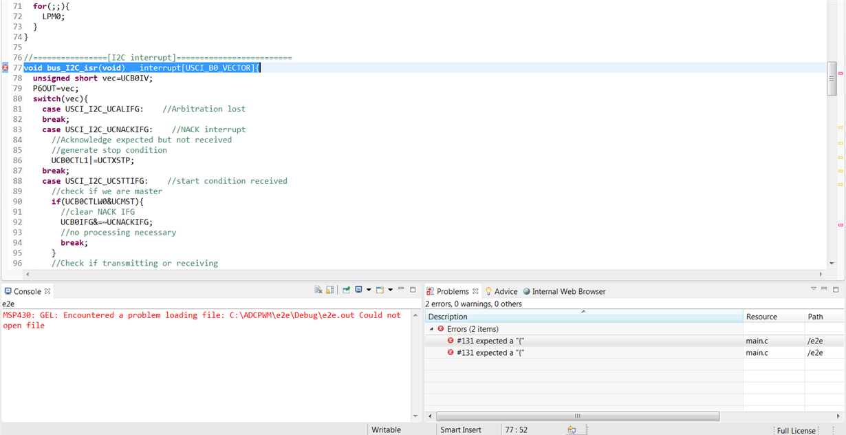
    Sorry for the late reply, I'm currently using CCS to compile the code and test on a target board,  there are errors concerning the "{" usage with both I2C interrupts. I don't know why this error exists, are you also using CCS?

    Additionally, on line 142, there is an extra break statement in the I2C interrupt code:

    Maybe that is the reason for your missing transmission.

  • I am using Rowley CrossStudio 3.0 I suspect the problems may be related to how CCS expects you to declare interrupts and that may need to be adjusted.
    I am not sure why the extra break is there, probably a coppy-paste goof up. Regardless the first break should cause code execution to leave the switch statement making the second break unreachable and have no effect.
    The question is not "why do I not send the correct data" but "why does the I2C respond to itself." The missing transmission is caused by getting receive interrupts which cause the index to be incremented more than it should. This could be fixed by changing how the indexing is done but I would rather understand why I get these interrupts in the first place.
  • That interrupt definition needs to change from:

    void bus_I2C_isr(void) __interrupt[USCI_B0_VECTOR]{

    to:

    #pragma vector = USCI_B0_VECTOR
    __interrupt void bus_I2C_isr(void) {

    in order for it to build using the TI MSP430 compiler rather than Rowley CrossStudio as used by Jesse.

  • Hi Jesse,

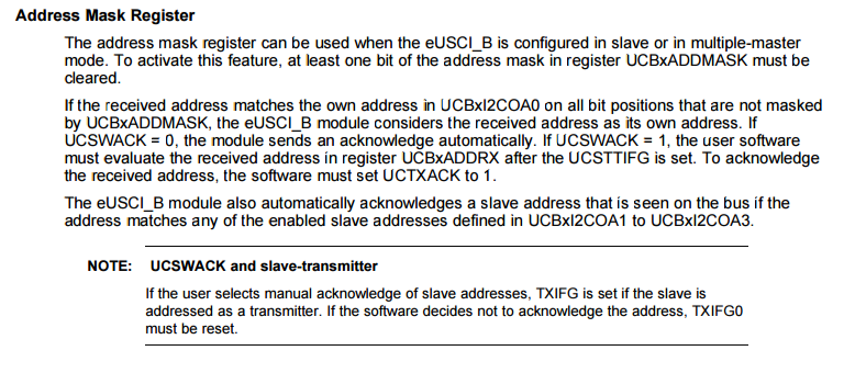
    I think the issue is due to the use of the multi master, and can be solved with the address mask register. Referring to the user guide, UCSWACK can be used to check the received address and make sure it's not the master but the slave. I don't think the peripheral is sending data to itself, but an interrupt can be used to check master transmission. You can refer to section 41.0.12 of the user's guide with regards to I2C Multiple Slave Addresses and Transmit Interrupt Operation. I hope the information regarding address mask register helps with regards to  master-slave multi master ACK.

    Sincerely,

    Sean

  • It IS sending data to itself. The peripheral sends both transmit and receive interrupts during the transaction. This is not the same behavior that was observed with the older USCI. The address mask feature is not active because no bits of the UCBxADDMASK register have been cleared. I guess the UCSWACK bit could probably be used to filter out the filter out it's own address. I would still like to see some mention of this in the diagrams in section 39.3.5.1

**Attention** This is a public forum