This thread has been locked.

If you have a related question, please click the "Ask a related question" button in the top right corner. The newly created question will be automatically linked to this question.

MSP430G DC MOTOR BOOSTER PACK DRV8848

Other Parts Discussed in Thread: DRV8848, BOOST-DRV8848, MSP430G2553, TINA-TI

Dear Sir:

     I recently de-boxed the MSP430G Launchpad DC Motor Booster Pack DRV8848.  

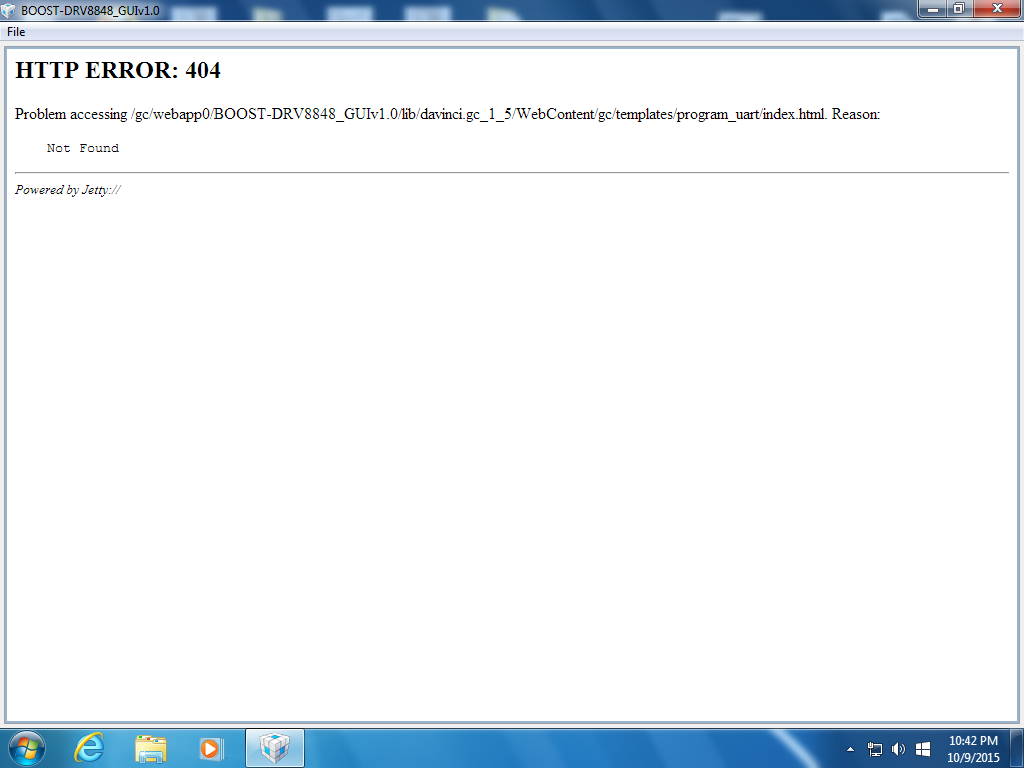
     I tried to run the GUI that is intended to run with the booster pack.   However, I received a reply from the web telling me that there was a "HTTP ERROR 404" - a file was not found.    I have attached a "screenshot" to show you the exact message that I received.  

     Can a TI engineer please tell me why the GUI did not work correctly?

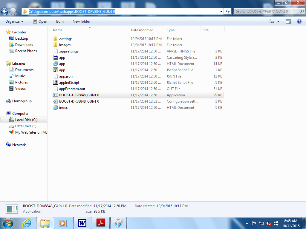
  • As a follow up, it would appear that my installation directory set up is valid.  Enclosed is a screen shot. 


    I noticed that I may be missing a *.lib file.   I conducted a conventional installation of the TI download but it appears that I am missing the *.lib file.   


    See the first screenshot that references the *.lib folder.  


    This is a theory as to why the GUI may not be operating correctly.  I am not certain why the GUI is not working. 


    Can a TI engineer explain to me why this typical, conventional, download and installation is not working.

  • Hi Michael,

    I am transferring this post to the Motor Drivers Forum as BOOST-DRV8848 questions can be best answered by them. I have also alerted the proper design engineers to your question so they should be returning with a response soon.  I would also encourage you to review all material found in the User's Guide: www.ti.com/.../slvuae1.pdf

    Regards,
    Ryan

  • Hi Michael,

    Strange, I have not seen this error before. It seems like the GC Runtime ran into an error when it tried to open the app. I will ask the team here if they have seen this before.

    Can you confirm a few things...

    • What version of the GUI Composer Runtime did you install?
    • You are using a MSP430G2 LaunchPad with an MSP430G2553 device, correct?
    • The LaunchPad was programmed through CCS?

  • Dear Nick;

         Thank you for replying to my post.

          I am not exactly certain about the "Runtime" term that you used when you wrote:

    "What version of the GUI Composer Runtime did you install?"

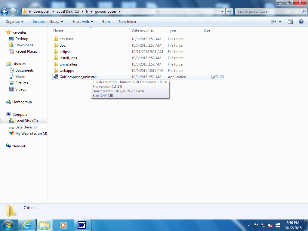
          Therefore, I am enclosing a "screenshot" of what I believe is the information you are seeking:

    To answer your question: 

    " You are using a MSP430G2 LaunchPad with an MSP430G2553 device, correct? "

    Yes, I am using the MSP430G2 LaunchPad with an MSP430G2553 device.

    To answer your question:

    The LaunchPad was programmed through CCS?

    Yes, the Launchpad was programmed using the CCS IDE.

    Can you please tell me why the user of the Launchpad and BOOST kit has to use a GUI interface that appears to be associated with HTTP?

    Why couldn't TI send a simple, self contained, GUI application program?  What were the advantages of using this type of  GUI interface method?

    Again, I would like to thank you for your reply and I am looking forward to reading your reply to my question.

  • Hi Michael,

    Thanks for the information. I was looking for which run-time version was installed from the below link. It is recommended to always install the latest.

    http://processors.wiki.ti.com/index.php/Category:GUI_Composer#GUI_Composer_Runtime

    We use the GUI-C tool since it is integrated into CCS and allows us to create simple apps that a customer can also modify. It also provides a simple interface to most TI MCUs. The team thinks that possibly an install error happened or an outdated version of the runtime is in use.

    I would recommend uninstalling your current version and then installing the latest version from the link above. After you install the runtime, you can place the app in the webapps directory and try running as before.

  • Dear Mr. Oborny;

         Thank you for your reply.   

         Before I uninstall the old GUI Composer, it my belief that I should inform you that I have bought lots of kits from TI and I always installed the software that is supposed to go with the kit.   The old GUI composer program that I am currently using was originally installed to support other TI kit GUIs.   I am worried that if I uninstall the old software and re-install new GUI software those kits won't work properly anymore.   Can you tell me if there exists another workaround so that I can keep my old software?

          Also, I appreciate your reply answering why TI uses the GUI app.   However, can you tell me why this GUI interface utilizes web based tools?   What advantage was the use of these tools, as opposed to stand alone programs?    Why is utilizing web based tools necessary?

          I am just curious and I can't understand why the extra web based software overhead?    What functional purpose does web based data processing offer?

          Thank you for your past replies and, again, I will be looking forward to reading your next reply.


  • You should be able to install the new version into a different directory, just change the name of the install directory. I have done something similar for my machine. I believe some of the c2k kits utilize a subset of the GUI Composer Runtime. This subset of GUI-C does not contain the libraries for MSP devices.

    The app is not actually accessing the web when it is running. GUI Composer is a standalone tool. I believe you see an error similar to a web access error because GUI C uses a web based formatting for creating the GUI (HTML + JavaScript). It is convenient to use HTML and JavaScript for GUI creation as it a well know format and language for creating visual interfaces. But the app is running entirely local to your machine.

  • Dear Mr. Oborny;

    I would like to thank you for your information, the download and install of the latest GUI Composer software package resulted in a working GUI.

    I immediately began working on finding suitable working code that is compatible with the launchpad pin outs for this kit. I want to avoid working with GUI composer because I will not be using this program for my applications.

    Can you please directly link me to a program that I can download to the Launchpad via CCS that will spin my motor?

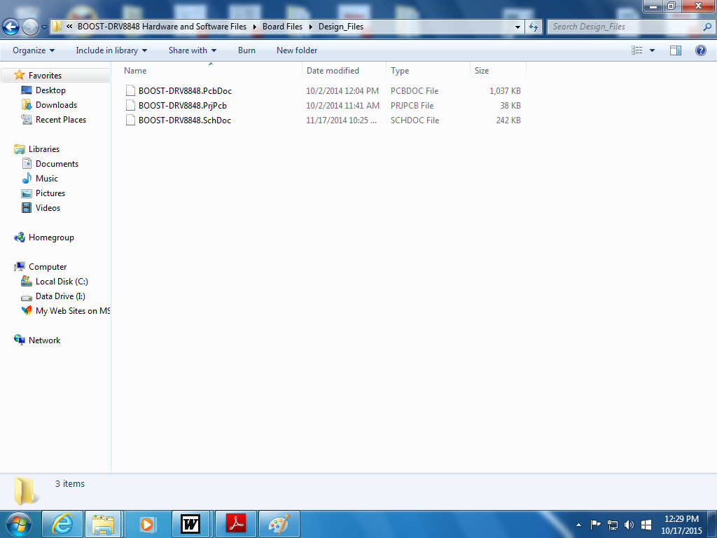
    Also, when I began to overlook the kit schematic diagram that was offered to the user in *.pdf format, I found the schematic diagram to be unsuitable for my needs. Therefore, I began to look at what I believe to be the actual software files used to create the booster kit PCB board and the schematic diagram in program form. I would like to read and analyze these files if they contain the information that I seek.   Below is a screenshot with regard to the files that I would like to be able to read and modify:


    Can you please tell me if TI offers a program for its customers - a software package - that can read all the files contained in this booster pack and if not can you direct me a software packages (hopefully a free software package) that will be able to duplicate the Launchpad PCB and the motor booster pack?

  • Michael,

    This is the only demo software we provide for this kit at the moment. You are more than welcome to modify it to run without interface from the GUI or create your own application using CCS.

    The PCB source files for the BoosterPack are for Altium as this is the development tool we utilized. We also provide the complete Gerber files for the design. TI does not deal with PCB creation tools, we just provide examples using our devices.

  • You can find generic CAD/CAE symbols for all of our devices under the Quality and Packaging Tab of the product folder.

    www.ti.com/.../quality

  • Dear Mr. Oborny;

         I would like to thank you for your replies. 

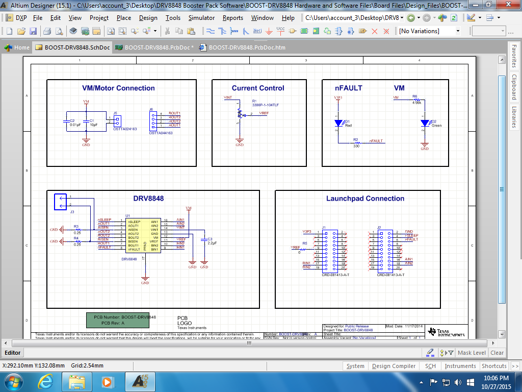
         I would have replied sooner.  However, installing and obtaining the Altium product was a difficult, convoluted, process.  I finally did install the trial software and obtained my license.    Afterward, when I looked at the BOOST schematic in Altium, I discovered that it was the same deficient schematic that I originally observed. 

         I have uploaded a screenshot of the schematic so that you may be able to observe what I have observed.  

         As you can see this schematic is deficient.    The customer wants to see exactly how the MSP430G2553 is connected to the BOOST brushed DC motor kit. 

         I really have to say, the decision to use this schematic was a complete and total mistake.    An engineer, technician, student, or a hobbyist, wants to see the complete circuit, not disconnected portions of a circuit.   

         I have purchased a lot of TI development kits and since this was the first kit I had the opportunity to observe, I decided to invest some time in the Altium download and install because I thought that it was possible that my other kits may also use Altium schematics.   

         My question for you is:

    Is the uploaded image the complete schematic?  Or, did I overlook a file?   I expected to download and use a "virtual" circuit.    A "virtual" circuit in the sense that analysis and modifications can be made on the circuit.   I was hoping for something similar to a PSPICE *.CIR input file. 

    Can you please tell me if I have overlooked a file (I am new to the Altium IDE)? 

    Thank you for your past replies.


  • Michael,

    The LaunchPad schematic is not included here as it is not the same PCB. This is a daughter board for the LaunchPad. As we do not know for sure which LaunchPad the BOOST-DRV8848 will be connected to we do not attempt to provide it here. It you know what specific LaunchPad you are using you can find it's schematic as well on ti.com.

    http://www.ti.com/ww/en/launchpad/launchpad.html?DCMP=mcu-launchpad&HQS=launchpad

    The connections to the LaunchPad connector are indicated with the "LaunchPad Connection" section. You will find similar connectors on the LaunchPad. I admit that the connections may not be obvious but we try and follow a similar format where the left header on the BoosterPack schematic is associated with the left connector on the LaunchPad with similar orientation and same for the right connector.

    I'm sorry for the miss-understanding but there is no simulation model available for this PCB at the time being. This is a PCB CAD schematic, not a circuit simulation.

    Altium is a PCB CAD tool, similar to many others out there. The majority, but not all of TI's eval boards are done with it.

  • I would like to thank you for all your helpful advice. 

    I was just passing on customer feedback with regard to what the customer needs when he purchases a TI kit.     I am not referencing you personally, I know that you probably have nothing to do with how the kits are marketed to the general public.    

    Generally, people like the "nuts and bolts" of a design better than the "bells and whistles."  A real engineering schematic diagram would have been a lot more helpful than those pictures that are attempting to substitute for a schematic diagram with connected parts..   Hopefully, someone a the top will respond to this bit of advice and recommend better schematic diagrams.

    Again, I would like to thank you for your helpful replies.  If you want to verify your answer with regard to the "working" software installation, write back and tell me how and I will verify your answer.   Thanks for your help, it was appreciated.

  • I tried to verify this correspondence. Hopefully, it will work out. Again, thank you for your excellent advice.
  • Michael,

    Can you clarify what the customer mean's by a "real" schematic? The Altium CAD schematic provided is as real as they come. These are not bells and whistles, but electrical connections that are sent to the CAD layout tool which is used to generate the netlist and gerbers for the PCB manufacturing. Connections are made through wires and net ties as is shown in the Altium schematic. Altium is an industry standard tool for this process.

    Do you mean that they are looking for an entire electrical simulation of the schematic (SPICE, PSPICE, Tina-TI)? These are entirely different things and generally not merged with most PCB CAD editors. This is simply not possible from a resource standpoint to create these in addition to the CAD designs. TI often provide SPICE models for specific ICs and subsystems, but creating a working simulation model for an entire application system is not a simple task.