This thread has been locked.

If you have a related question, please click the "Ask a related question" button in the top right corner. The newly created question will be automatically linked to this question.

Simple word/speech recognition

Other Parts Discussed in Thread: MSPWARE, TEST2

Hi,

I need to design a simple word/speech recognition application where any user can say something like led blink, on or off and an led will respond. I've been given the msp-exp4305438 experimenters board from my university, which comes with a microphone on the board. Does anyone have any good references/resources they can share to first help me learn in general how VR works and secondly how I could implement it in C with the msp. I haven't been able to find a good tutorial on the basics of VR. 

Thanks,

Micah

  • Msp430 usually is not considered as first choice processor for Voice Recognition because proper VR requires lot of computing power and data/code memory. I doubt you will succeed finding anyone who did VR on msp430, but who knows. Did you try internet search? Did you try asking in the TI DSP microcontrollers forum?
  • I have not posted on the DSP forums yet, that is a good idea. I don't suspect this project will need a ton of computing power since I just need to analyze a few short words. I don't need any prediction modeling or large vocabulary libraries stored. And besides, the msp430 is all I have to work with from my University.

  • If you plan to do just spoken word "recognition" using training/fingerprinting approach then yes - you can do it even on small msp430, however your requirement is "any user can say something like led blink" where actual problem is encoded in word "any".
  • Speech recognition is challenging and usually requires quite a bit of compute power. Its a computation/performance tradeoff issue. The two basic steps are feature vector extraction, and pattern matching of speech features to the model for a word or phrase. Feature vectors are usually spectrally based. Pattern matching can be done by a variety of methods. One approach to ASR on the MSP430 could be developing simple spectral features followed by a dynamic time warping to do the pattern matching. That is an old approach and there is a wealth of information on speech recognition features and DTW pattern matching when searching the web. The two main problems that you will encounter given your task are the differences between the way speakers say the words or phrases, and interfering background noise and speech. Ways to mitigate these problems for a small platform are to create separate models for each speaker, and if possible, constructing a push-to-talk ASR system. One can also improve performance greatly by a correct choice of acoustically distinct words. Rather than choosing short similar words like "on" and "off", words like "activate" and "shutoff" could be considered. An MSP432 would also provide additional power for more sophisticated processing.
  • Thank you Lorin. I think your message is very helpful. It seems the most difficult part will be the pattern matching.

  • I am now currently working on the pattern matching aspect of this project and I am struggling to understand a block of demo code from the 'user experience' demo from TI. I am trying to understand where the recorded sound is stored (in flash I know, but what variable or how do I access it). I was expecting just an array of data that I would be able to step through and look at but it does not seem to be so. The function that does the actual recording I believe is this:

    /**********************************************************************//**
    * @brief Executes the record.
    *
    * - Unlocks the Flash and initialize to long-word write mode
    * - Initializes the Timer to trigger ADC12 samples
    * - When the operation is done, locks the flash, disables the DMA, and stops
    * the timer
    *
    * @param none
    *
    * @return none
    *************************************************************************/

    static void record(void)
    {
    halLcdPrintLine(" Recording ", 6, INVERT_TEXT | OVERWRITE_TEXT);
    halLcdPrintLineCol("Stop", 8, 12, OVERWRITE_TEXT);

    FCTL3 = FWKEY; // Unlock the flash for write
    FCTL1 = FWKEY + BLKWRT;

    DMA0CTL = DMADSTINCR_3 + DMAEN + DMADSTBYTE + DMASRCBYTE + DMAIE;
    // Enable Long-Word write, all 32 bits will be written once
    // 4 bytes are loaded

    TBCCTL1 &= ~CCIFG;
    TBCTL |= MC0;

    __bis_SR_register(LPM0_bits + GIE); // Enable interrupts, enter LPM0
    __no_operation();

    TBCTL &= ~MC0;
    DMA0CTL &= ~(DMAEN + DMAIE);

    FCTL3 = FWKEY + LOCK; // Lock the flash from write
    }

    How is this function storing the data into the flash? I can't make sense of it.

    Thanks,
    Micah
  • >How is this function storing the data into the flash? I can't make sense of it. 

    This function instruct DMA controller to move data w/o CPU intervention. Source and destination address, total bytes of transfer are set-up elsewere. This function just enables flash write , starts DMA copy process, waits for DMA completion interrupt to occur and after that disables DMA and flash write mode.

  • Ok, that makes sense. I still am not sure where the actual data is being stored however. The function that calls the one above is this:

    void audioRecord(unsigned char mode)
    {
    unsigned char i;

    setupRecord();

    halLcdPrintLine(" Erasing ", 6, INVERT_TEXT | OVERWRITE_TEXT);
    halLcdPrintLineCol("----", 8, 12, OVERWRITE_TEXT);

    // Not used in User Experience sample code
    if (mode == AUDIO_TEST_MODE)
    {
    flashErase(MemstartTest, AUDIO_MEMEND);
    __data16_write_addr((unsigned long)&DMA0DA & 0xffff, (unsigned long)MemstartTest);
    DMA0SZ = (long) (AUDIO_MEMEND - MemstartTest);

    record();

    if (DMA0SZ != ( long) (AUDIO_MEMEND - MemstartTest))
    lastAudioByte = AUDIO_MEMEND - DMA0SZ;
    else
    lastAudioByte = AUDIO_MEMEND;
    }
    // Always used in User Experience sample code
    else
    {
    flashEraseBank(AUDIO_MEM_START[0]);
    flashEraseBank(AUDIO_MEM_START[1]);
    flashEraseBank(AUDIO_MEM_START[2]);
    flashErase(AUDIO_MEM_START[3], AUDIO_MEM_START[4]);

    for (i = 0; i < 3; i++)
    {
    __data16_write_addr((unsigned long)&DMA0DA & 0xffff, (unsigned long)AUDIO_MEM_START[i]);
    DMA0SZ = AUDIO_MEM_START[i + 1] - AUDIO_MEM_START[i] - 1;

    record();

    if (DMA0SZ != AUDIO_MEM_START[i + 1] - AUDIO_MEM_START[i] - 1)
    {
    lastAudioByte = AUDIO_MEM_START[i + 1] - DMA0SZ;
    break;
    }
    else lastAudioByte = AUDIO_MEM_START[i + 1] - 1;
    }
    }

    shutdownRecord();
    }

    It would seem that the data is being stored in AUDIO_MEM_START, however it is only an array of length 5 and each block doesn't change when I test it with sound input. I am pretty confused, anything could be helpful.
  • Usually an automatic speech recognizer needs to process audio data in real-time. This is often done by collecting "frames" of audio data in a Ping-Pong buffer. While audio data is being collected in one buffer, the ASR is processing the data in the other. Real-time must be maintained, that is, the recognizer must complete processing the data in one buffer prior to the next one becoming available. On the MSP430 this can be done using the ADC and DMA. I have extracted audio capture code I used for such a project and it is attached. The target board was the MSP-EXP430F5438. The code and comments can help show how to set up and collect audio data.Hope this helps. 

    audio_capture_01_00_bsd.zip

  • Thanks Lorin for the code. I am not quite at this point yet. I am trying to locate the data that is being transferred from the DMA so I can have my voice data template. Once I can have that data in vector format then I plan on comparing the incoming data with the template. Does your code work without configuring some settings? It doesn't appear to be updating data. 

  • I guess a better way to ask this question is why is this line in the code above
    for (i = 0; i < 3; i++)
    {
    __data16_write_addr((unsigned long)&DMA0DA & 0xffff, (unsigned long)AUDIO_MEM_START[i]);
    DMA0SZ = AUDIO_MEM_START[i + 1] - AUDIO_MEM_START[i] - 1;

    before the record() function which from what I understand sets up the dma. So then the data is written from the adc into AUDIO_MEM_START? But then the question becomes why is AUDIO_MEM_START only an array of length 5? I would expect it to be much larger.
  • >why is AUDIO_MEM_START only an array of length 5
    AUDIO_MEM_START[] is not sample buffer where audio samples are stored but 5-element array of pointers to flash memory _blocks_
  • Alright I think I'm finally getting it. There is still a lot I don't understand but I believe the data is being stored inside the TB0CC4 register.
    counter = 0;
    TBCCR4 = (*((unsigned char*)PlaybackPtr));
    PlaybackPtr++;
  • > I believe the data is being stored inside the TB0CC4 register.
    Code you posted is not about storing but playback using timer PWM. Together with external lowpass filter it forms audio DAC.

  • In what way does it not appear to be updating data?

    In the code, Abuffer consists of two frame buffers Abuffer[0][] and Abuffer[1][]. The code sets up the DMA so that it transfers samples from the ADC into one buffer, starting with Abuffer[0][], until the buffer is full, then interrupts the processor to tell the application program that a buffer of data is available, and then immediately starts filling Abuffer[1][] with samples from the ADC. This procedure keeps occurring, toggling back and forth between filling Abuffer[0][] and Abuffer[1][]. It is up to the application program to process the data in each Abuffer when the data becomes available - put the application code in place of the do-nothing for loop that is a placeholder for application processing in the function audioCapture.
  • In response to Ilmars,

    I realize this is a part of the playback code, but really that's what I need. I just need to be able to read the data from the flash, store it into some dummy array, then compare with the incoming data using the method Lorin described above. Shouldn't this effectively read from this flash?

                        
                        test[blah] = (*((unsigned char*)PlaybackPtr));
                        blah++;
    where PlaybackPtr is originally pointing to the first flash memory address ?

    In response to Lorin,

    Right, I understand this code is not processing any data. But the data collection also seems odd in that the data in Abuffer will change but it ranges from about -30000 to -28000 and doesn't seem to change in a way that correlates with my voice. WIth the user experience audio capture I was receiving data in range from about 50-250 that I could definitely see was changing with my voice. 

  • >Shouldn't this effectively read from this flash?
    During (continuous) speech recognition flash will wear-out very quickly and microcontroller will become bricked. Check msp430 flash endurance data and you will see why. You shall store voice recognition data in the flash, as temporal sample data storage use RAM.
  • In extracting the capture code from my project, I may have missed something. I will check it out.

    I have also noticed that when the microphone preamp is first powered up by setting the IO port pin high, the ADC output is almost saturated until the power on the op amp stabilizes. So I have to wait a while before receiving valid audio data in the buffers. That may explain the large numbers you observe. Were the large values consistent over many seconds of observation?
  • How long should it take for the op amp to stabilize? I left it running for about 5 minutes and the data was still very high. And yes it seems to be consistently high values.
  • It should only take a second or so. The values should not be consistently high. Can you tell me what EVM you are using. Thanks.
  • Interesting. I am using the msp-exp430F5438. Are you getting similar results on your end?
  • The problem is that I did not set the clocks up in the example code. MCLK should be set to 16MHz. I will update my code, test and repost it.
  • Did you get it to work? I am trying to configure the correct pmm settings but no luck so far.
  • Yes. I did get it running on the MSP-EXP430F5438. Yesterday I added code to stream the audio data from the board USB UART to the PC. That way you can collect the audio and then examine it offline on the PC. It will take a little while for me to get the code packaged, and then I will send it in another post.
  • Included in this post is the code to capture audio data in a Ping-Pong buffer and stream the data out of the MSP-EXP430F5438 USB UART port. The data is collected at 8kHz sample rate. Depending on how the streamed data is read and stored by the host PC,  it may have to be byte swapped.

    audio_capture_01_01_00_00_bsd.zip

  • Thank you very much. I'll fire this up tonight. If I have trouble understanding it I'll let you know. 

  • Lorin I have two questions:

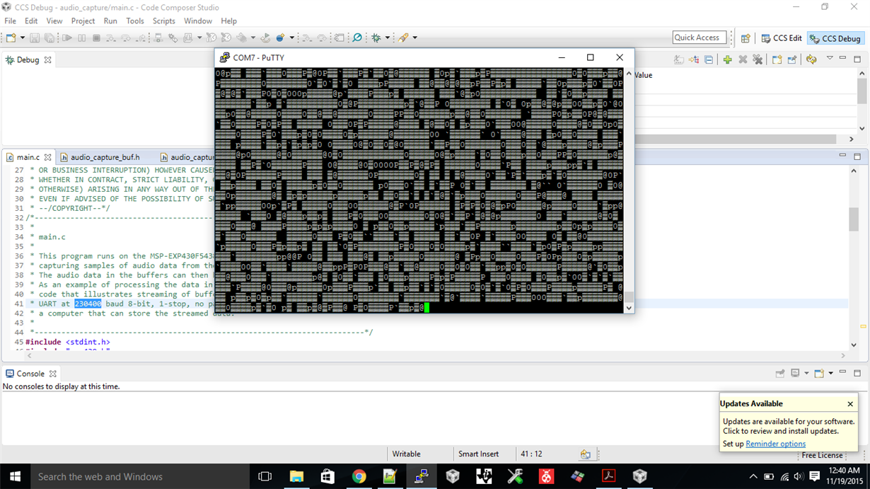
    What do negative numbers in the context of the captured audio mean? I was expecting everything to be absolute value. Secondly, the uart output is garbage data on my screen. Could this be a symptom of having to byte swap the values? I am sure I set the baud rate to 230400 and I can tell that the data matches of with whatever sound there is. 

  • Micah,

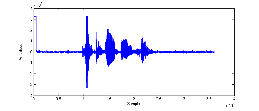
    It actually looks like you have got it working. I also use PuTTY, and the output is supposed to look like nonsense.  That is because the program streams raw binary audio data samples. The code is written so the ADC will output audio samples as 16-bit two's compliment binary audio samples to the buffer. These two's compliment binary samples are streamed to the PC a byte at a time. Set PuTTY to capture all data in the log file. Its also a good idea to set PuTTY to not output any bell sound, since the binary audio data bytes will randomly match the ascii bell value. After collecting data for a while, stop collection. Then open the log file in some program that can read and plot binary data, such as Matlab. You should get a signal showing the speech data as shown below. If it does not look like a speech signal, then bytes may have to be swapped, since PuTTY sometimes seems to have some extra bytes at the beginning of the log file.

  • Hi Lorin,

    My data plotted by matlab definitely doesn't look like a audio signal, as all the values are positive. Byte swapping this data would still give a positive value, so that makes me think the data needs to be swapped before its sent to putty. I am confused how to do this. From what I understand, the code sends the data through UART with this:

    // Transfer data to USCI_A1 trasmit register UCA1TXBUF
       __data16_write_addr( (unsigned long)&DMA2DA & 0xffff,
                           (unsigned long)(&UCA1TXBUF) );

    inside the setupCapture function. My question is how could I edit this data before it is sent if its being transferred from the dma behind the scenes. As well, the setupCapture function is only called once in the beginning so I am also confused how each frame is sent via uart if those lines are only called once. Thanks for your help. 

  • I am very confident this code does work. it should not be necessary to byte swap or alter the data prior to transmitting it. Would it be possible for you to record some audio with the program and share the PuTTY log file with me?

    The line of code you listed just sets up DMA channel 2 with the destination address of the DMA transfer, which is the UCA1 UART transmit buffer. It does not start any transfer. The actual transfer is accomplished in the audioCapture function while loop. Look at the lines of code following the comment:

    /* To stream data include the following instructions */".

    The first line of code sets the DMA channel 2 source address to the audio buffer that now contains valid audio data. The second line of code enables DMA channel 2 to start transferring data:

    DMA2CTL |= DMAEN;

    Only when this instruction executes, DMA transfer begins. You can do anything you want with the data in the buffer prior to executing this instruction.

    The while loop in audioCapture executes once for each frame. The comments explain how this happens. Prior to entering the while loop, DMA channel 1 is started and it is transferring samples from the ADC to the audio buffer memory. At the beginning of the loop the processor is put in LPM0 (low power mode 0) which shuts down the processor until some interrupt takes it out of LPM0. When it has transferred 160 samples, DMA channel 1 generates an interrupt. The interrupt code sets up DMA channel 1 for the next transfer by pointing the destination to the other ping pong buffer, and then restarts DMA channel 1. The interrupt also takes the processor out of LPM0, so that when the interrupt finishes execution the processor will continue executing the while loop in audioCapture.
  • Ok, thanks. Its make more sense. Ive attached some recorded audio. Out of curiosity, did you try or were you able to extract the FFT code from the users example? I am having a heck of a time integrating that code into this one. audioCapture1.brd

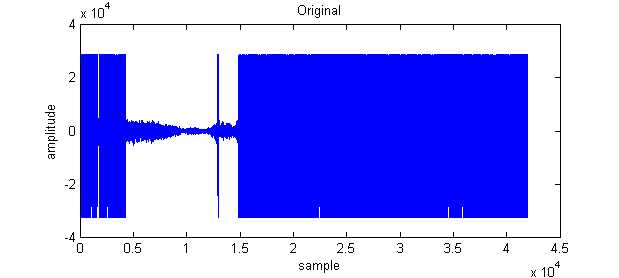
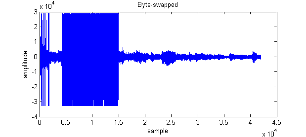
  • I looked at the data you sent me. I plotted both the original data, and the data byte-reversed. They are shown below.  It appears that at some points in the transfer of the data bytes are being dropped.  I played the section of code in the original data in the range of samples between about .5e4 and 1.5e4, and in the byte-swapped data between about 1.5e4 and 4.2e4. These are valid audio signals. The byte dropping does not happen in my tests. You could try to record again with the PC running as few apps as possible to see if that helps. 

    I have not tried to extract the FFT code from the UserExperience demo code. Since the FFT is written in assembly it may be a little more difficult to adapt to your application.  You might also want to look at FFT example code in the MSPWare  IQMathLib example. Under MSPWare look at iqmathlib -> examples ->CCS->msp430

  • Huh, interesting. I'll look further into why my PC may be doing this. In any case, my application does not critically depend on the uart streaming, but its a nice feature.


    I was able to integrate the FFT code. It took some fishing but it is now working. For your code, it is wise to extent the frame size to 1024? The reason I ask is the because the FFT code performs a 512 point FFT and the audio is stored into a buffer of size 1024.  I suppose I could also collect enough samples then truncate to the necessary length if the frame size is best at 160.

  • If doing speech recognition, the frame size depends on the rate at which speech phonemes change. The 160 samples collected at 8kHz yield a 20ms frame rate, which is typical for low-resource recognizers and the speech spectrum is fairly stable during that time. With more resources, recognizers use 10ms or lower frame rate, and may increase their sample rate to cover a wider spectral range. Often the 160 sample frames are padded at the leading end with samples from the prior frame in order to get to, say, a 256 sample FFT, which is easier to implement. It also provides some smoothing context. The 256 sample data is also often multiplied by a window prior to doing the FFT. I don't think it is a good idea to truncate or discard samples.
  • Why would the frame be padded with samples from the previous frame? Why not zero pad to the appropriate length?

    Also, what matlab commands are you using to generate those plots above? I am plotting the same data and am not getting valid audio data. My matlab code is as follows:

    fileID = fopen('test2.bin');
    A = fread(fileID);
    B=swapbytes(A);
    figure(1);
    plot(A);
    figure(2);
    plot(B);
  • By padding, I mean use a portion of the prior frame data at the beginning of the FFT buffer, followed by the current frame data so the data is in proper sequential order. As mentioned, this allows an FFT with all data points from valid sampled data, and allows some prior spectral content. Windowing the 256 samples smooth's the resulting spectrum. As long as the data is there it makes sense to use it. At the same time the desired frame rate is maintained.

    Matlab code I used is:

    >> fid = fopen('audioCapture1.brd','r');
    >> A = fread(fid,inf,'short');
    >> plot(A);
    >> B = double(swapbytes(int16(A)));
    >> plot(B);
  • Yea I understand why you need to window and pad the vector, but it seems like extra computation to include some of the previous frame's data in the current frame. I could be wrong but wouldn't just zero padding every vector give the same result?
  • Yes, it is a little extra processing to move some data from the prior frame to the FFT buffer. But, it is very little compared to what the recognition processing requires.

    From a mathematical perspective zero padding is not the same as using some of the prior data to fill the FFT buffer. The input data vector is different so the resulting FFT values will be different.

    If choosing to zero pad the FFT buffer, make sure the window is located symmetrically about the data samples.
  • Hi Lorin,

    I followed your advice to pad the current frame with the prior frame to the appropriate length. I am having some problems when I apply the window however. It seems that when I include the window code: 

    for (i = 0; i < 256; i++)
          {
        	  double multiplier = 0.54 - .46*cos(2*PI*i/255);
        	  voice_data[0][i] = multiplier * frameZeroShift[0][i];
        	  voice_data[1][i] = multiplier * frameOneShift[1][i];
          }

    the interrupt is called several times in a row and processAbuf repeats its value, thus not allowing me to apply the window to voice_data[0]. Do you know why this could be happening? It seems strange. Could it be from the cos function that is called?

  • The main problem in the code is in the line making the cos function call. These types of issues are encountered often in writing efficient DSP code. The buffer interrupt is occurring every 20ms. If the processor is running at 16MHz, this means that it must complete all processing for a buffer of data in the 20ms, or about 320,000 instructions at best (many instructions will take more than one cycle). So each iteration of the loop must take less than 1250 instructions at best, or it will not complete the loop before the next interrupt occurs. Actually, the processing of the loop must take much less than 1250 instructions in order to have cycles remaining for the recognition processing. Since this MSP device does not have a floating point hardware unit, processing of floating point data uses function calls to implement the operations. Efficient use of cycles is paramount.

    In this loop the multiplier values remain constant for each frame of data. So the values of the window multiplier array should be calculated offline, and stored as a constant vector in flash memory. That way it will not have to be calculated at all in the loop.

    Another issue is that specifying multiplier as a double requires all multiplication to be double precision real values. Using a regular float would require less computation.

    To make the loop run in very few cycles, it can be written in fixed-point, keeping track of precision and decimal points. That way in the loop the sample data values and multiplier values can be written explicitly and immediately to the MPY32 peripheral multiplier memory-mapped register variables and the multiplication result from the MPY32 can be transferred to the output array. This is the method I often use. It requires understanding of the MPY32 peripheral, but it is very fast.

  • I see. So I probably won't even be able to run the dtw algorithm without the MPY32. Do you have an example on how to use it in C? I can only find examples in assembly. 

  • The problem is more with using floating point than MPY32. The floating point functions require maintaining the mantissa and exponent, which is a lot of extra work. Fixed-point processing will be much faster, and the compiler will generally use MPY32. It may not fully utilize the capabilities of the MPY32 such as the ability to perform a multiply-accumulate operation. You may need to code such a case manually for best performance.

    An example of C code using MPY32 is found in the MSPWare Driver Library which has functions that implement usage of the MPY32. You can look at the detail in each function for the C code that directly interacts with the MPY32 peripheral. The compiler will usually implement more efficient code than that in the Driver Library, however, avoiding the overhead of function calls. First use the compiler. If there is a bottleneck at a certain operation, then it could be hand-coded in C.
  • So I've included the QMathLib library from TI to compute the cosine function. It appears that this function combined with the data shifting operations is still too time consuming. I haven't included the time warping operation yet either. I am not sure how this will be possible. This is my code for shifting the data:

    if(bufCount > 1)
          {
        	  for (i = 0; i < 256; i++)
        	  {
        		  if(i==200)
        			  flag=1;
        		  if(processAbuf == 1)
        		  {
        			  frameOneShift[1][i] = frameZeroData[0][63+i];
    				  if(i>=96)
    					  frameOneShift[1][i] = frameOneData[1][i-96];
    				  if(i == 255)
    					  flag = 1;
    
        		  } //if processAbuf
    
        		  if(processAbuf == 0)
        		  {
        			  frameZeroShift[0][i] = frameOneData[1][63+i];
        		  	  if(i>=96)
        		  		frameZeroShift[0][i] = frameZeroData[0][i-96];
    
        		  }
        	  }
          }

    What options do you think I have? I know you said that the 160 frame size was optimal, could I possibly use a frame size of 256? This would reduce accuracy I suppose but it would take out the shifting operations. 

  • Please confirm that you are not calculating the Hamming window coefficients as part of the Hamming window processing loop. The Hamming window coefficients must be calculated offline and stored as a constant array of data, which will locate them in flash. That way the Hamming window weighting loop can simply be a multiply.

    If you have RAM memory available, what I would recommend is setting up two input audio buffers of length 256. Change the code that does the audio capture so that the DMA writes to the last 160 samples of each buffer, rather than the beginning part of the buffer. Then when the DMA has written a frame of data to the last 160 samples of the current buffer, immediately upon the DMA interrupt write the last 96 samples of the prior buffer to the first 96 samples of the current buffer that contains the new frame data. Here is example loop code I used in a project. Maybe memcpy might even be more efficient. 

         // Copy overlap data to currentAbuf for the frame, WIN_SIZE=256 FRAME_SIZE=160

          for( i = 0; i < WIN_SIZE - FRAME_SIZE; i++ )

          {

             Abuffer[currentAbuf][i] = Abuffer[priorAbuf][FRAME_SIZE + i];

          }

  • Presently I am not calculating any window coefficients, just to test if the code was fast enough. What do you mean by 'offline'? 

  • Oh. I thought you were still running the Hamming processing loop because you mentioned that you were calculating the cosine.

    By offline I mean calculating the Hamming window coefficients on a PC using Matlab, a program, or whatever. Then in the MSP code include

    the window coefficients as a constant array.

    int_least16_t const hamming[256] = {....};

    The code to set up one of the 256 point frames of data should only take about 100 or so cycles of the processor's time. There should be plenty of time left for processing.. 

  • Ah ok I gotcha. Sorry for the confusion. I was calculating the cosine of some random value in that code I posted earlier for testing its ability but removed it to avoid confusion.
  • Hi Lorin,

    It seems that my data is still being corrupted when I transfer it to my PC. This is making it difficult to create a template. I am running with only CCS open, do you have any idea why this could be happening? When I play the recording in Matlab its just static with bits and pieces of valid audio. 

  • My thought is still that somehow bytes are being dropped. I tried the audio capture code with CCS and several other programs open, and had no problem. Make sure that PuTTY is set to 230400, 8 data bits, 1 stop bit, no parity, and that under session logging "All session output" is selected.

    Are you sure the audio capture is finishing in the allowed 20ms? You may want to light an LED if real-time is lost. That can be done in the DMA interrupt.

    If you are convinced that real-time is not lost and PuTTY settings are correct, would it be possible to distill your code to simple audio capture/streaming, and share it so I could test?

**Attention** This is a public forum