This thread has been locked.

If you have a related question, please click the "Ask a related question" button in the top right corner. The newly created question will be automatically linked to this question.

MSP430G2553 PWM issue

Other Parts Discussed in Thread: MSP430G2553

Hello,

I am trying to generate a triangular waveform using PWM of MSP430G2553 capture/compare unit on MSP430 launchpad. PWM duty ratio is going up and down and filtered. Basically it works, but periodically something turns the output back on right after it goes low. I can't figure out why this happens. Seems when it happens, SCCI and CCI bit in TA0CCTL1 register goes high, but I think I disabled the capture.

P1.2 is shown in the figure.

The code is listed below. Any suggestion will be appreciated. Thank you.

#include <msp430.h>

#pragma CODE_SECTION(timer_a0, ".ram_func")

int x = 1;
int pulsecounter = 0;
int dur = 54;
int intv = 255;

void main(void)
{
	unsigned char *flash_start_ptr;           // Initialize pointers
	unsigned char *RAM_start_ptr;
	unsigned char flash_code_size = 0xE0;

 	WDTCTL = WDTPW | WDTHOLD;		// Stop watchdog timer 0.5 V step
 	BCSCTL1 = CALBC1_1MHZ;                  // DCO at 1 MHz
 	DCOCTL = CALDCO_1MHZ;                   // DCO at 1 MHz

	flash_start_ptr = (unsigned char *)0xC000;
	RAM_start_ptr = (unsigned char *)0x200;

	// Copy flash function to RAM
	memcpy(RAM_start_ptr,flash_start_ptr,flash_code_size);

    pulsecounter=1;
    P1DIR|=BIT2;
    P1SEL|=BIT2;
    P1DIR|=BIT6;
    P1SEL|=BIT6;

	P1DIR |= 0x01;					// Set P1.0 to output direction

	TA0CTL=TASSEL_2 + MC_1 ;
	TA0CCR0=intv;
	TA0CCTL0=CCIE;       // initiate interrupt

	TA0CCTL1=OUTMOD_6;
	TA0CCR1=0;
	TA0CCR2=0;

    _BIS_SR(LPM0_bits + GIE);   // go to sleep mode and initiate interrupts
}

long ccc = 0;
int ddd = 0;

#pragma vector=TIMER0_A0_VECTOR
__interrupt void timer_a0(void)
{
	P1OUT = 0x01;				// LED on

	if (pulsecounter < dur)
	{
		ccc = ccc + x;
	}
	else if (pulsecounter >= dur && pulsecounter < dur<<1 )
	{
		ccc = ccc - x;
		if(ccc < 0)
			ccc = 0;
	}
	else
	{
		pulsecounter = 0;
		ccc=0;
	}
	pulsecounter++;

	TA0CCR1 = ccc;
	TA0CCR2 = ccc;
	if(pulsecounter == dur)
		P1OUT = 0x00;				// LED off
}

  • TA0 is not buffer-latched so you can not change CCR1 or CCR2 without carefully consider if it will re-hit a match value again to soon,
    or of it will miss it due to the time it takes for the ISR to complete.
  • Tony Philipsson said:
    TA0 is not buffer-latched so you can not change CCR1 or CCR2 without carefully consider if it will re-hit a match value again to soon,
    or of it will miss it due to the time it takes for the ISR to complete.

     Hi Tony, this example can be it cross interrupt firing and change PWM on the fly but I tagged this to see if some TAxx related silicon issue was active.

     I am still investigating what happen, this is from motor controller after I got a big trouble from controller running motor at higher voltage, one H bridge mosfet and some other IC including MSP got burned by this issue, another board was running for a long time on a 36V 10A motor sometimes make some strange noise. Applied to high voltage motor, I started @60V some test then when  400V was applied when I braked suddenly motor this issue left PWM uncontrolled raising current near 100 Amp or more never charging the bootstrap capacitor so burning the half bridge too.

     Processor is MSP2553 QFN32, board under test is on the bench and I am trying isolate issue, PWM is generated from timer 1 interrupt is disabled CCR0 is set to 1040 and max PMW is set tl 1020.
     Output from Port 3 (bottom traces) are the worst, output from channel 2, the one running most of time are upper traces, they must be complementary to drive low and high side but one side behave worst. Timer 0 is used for timing purposes and generate regular interrupt but no PWM.

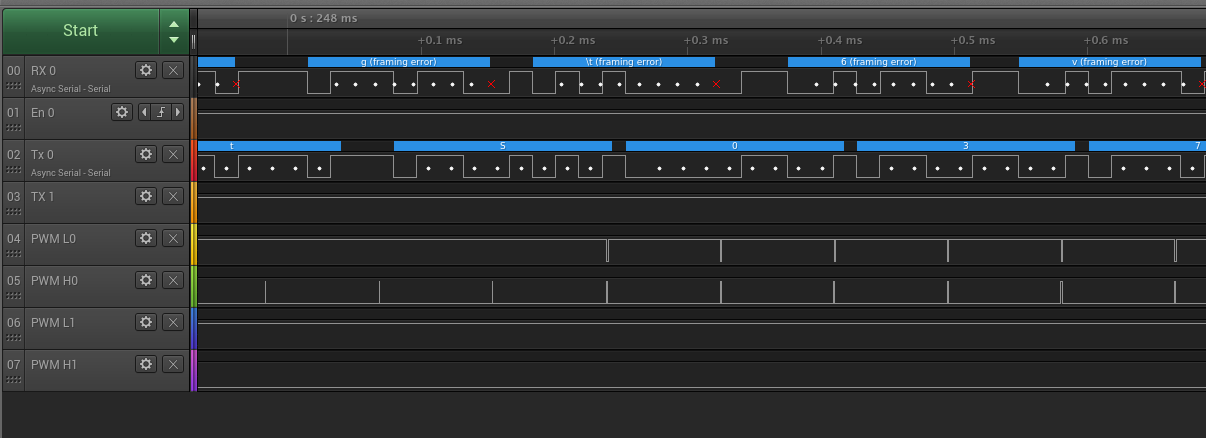
     here the waveform:

     complementary from port 3 are both high with some spike and big jitter.

     Here the port 2, timing on Low PWM value, waveform are correct but this strange phase shift appear, can be justified on ccr load but this can be just one cycle.

     Low channel is missing some pulses driving high also when high side driven, H bridge driver prevent shoot trough but this is unwanted...

    here again PWM channel stop and leave output High.

     Trouble on restart channel pwm is wrong, register are both at same value.

     Here after restart some jitter and noise are present on Low channel

     And here the worst, this noise on drive.

     This issue on same test repeat across different processors, both CCR1 and CCR2 get written at same time, I still don't know when this problem get fired but when appear first time then PWM is no more reliable.


     Code is compiled on CCS, the strange that same code compiled on IAR was less sensitive to this issue, the board from where waveform where taken is on bench without motor and power section, Bridge driver removed and connected to logic probe. At first glance appear as issue is related to some PWM values, and happen related to serial channel signalling too. Next week I try drive from constant drive and do some experiment on chunk of code generating PWM with and without communication protocol.
     I probably migrate design from G series to 55xx or old f22xx member served similar application with same software for years  or other processor too, this issue if not fully isolated can do severe harm on a huge DC motor.

  • I recently had some trouble generating pulses with the timer. Then I found the note in the family guide (slaa144) that recommends that the timer be stopped before changing its operation. That didn't help much when I was using TACLR to reset the counter but after I switched to changing the CCR values it worked.

    Try:

    TA0CTL &= ~MC_3;

    TA0CCR1 = ccc;

    TA0CCR2 = ccc;

    TA0CTL |= MC_1;

  • I think this "fix" can only fix a small percentage of the problem spots. It also has some undesirable side effects.
  • Does it make a difference between using the CCR0 CCIE and using TAIFG for a cycle-completion-interrupt? I always used TAIFG and never had any problems when updating the new CCRx values inside the ISR. But I guess your problem only occurs when having CCRx values at the very low end, right? I think I never had that case - the TAIFG interrupt also needs some cycles to be executed. Depending on the clock of the timer and the clock of the CPU, you will have the same issues when the CPU clock isn't much faster than the timer's one.

  • David Schultz36 said:

    I recently had some trouble generating pulses with the timer. Then I found the note in the family guide (slaa144) that recommends that the timer be stopped before changing its operation. That didn't help much when I was using TACLR to reset the counter but after I switched to changing the CCR values it worked.

    Try:

    TA0CTL &= ~MC_3;

    TA0CCR1 = ccc;

    TA0CCR2 = ccc;

    TA0CTL |= MC_1;

     Hi David, as from my problem where code is close to example stopping timer can help when you change mode of operation and not simply PWM reloading CCR register. Register are 16bit wide and this operation is atomic from register perspective. PWM issue appear when no writing is on it so I suspect some pattern sensitivity related to external events.
     IN my case defective timer is TA1xxx, TA0 is used to generate internal software timing.
     Stopping timer on change of PWM otherwise can generate some spikes and in my application where motor is rated 410V 56Amps void EMF certification, vibration control high order loop and security too so I prefer avoid this and rework board changing processor.

  • Dennis Eichmann said:
    - the TAIFG interrupt also needs some cycles to be executed. Depending on the clock of the timer and the clock of the CPU, you will have the same issues when the CPU clock isn't much faster than the timer's one.

     Hi Dennis, my first idea was to enable interrupt on Timer 1 and do an update on TAIFG, this idea was abandoned after seeing PWM was changing also if no write on it where applied.
     Original software was controlling Torque position speed and acceleration plus acceleration rates so PWM was changed near ever cycle or two, to try diagnose what was wrong I added a special mode just setting PWM from remote so when PWM stop work no update was performed due it is on middle of updating protocol frame.

  • Thanks for all suggestions. I tried the overflow interrupt (instead of compare interrupt) and different clocks for MCLK and SMCLK, slower SMCLK than MCLK, but it still remains.

  • Thank you for your suggestion, but it still happens in different timing.
  • I started to work on a structure based pwm
    I have not tested it yet, but it's 32bit fixed point accumulator. so you can add 1000 or you can add 0.0001 for example

    typedef struct mylongTag{                // create a structure of two words
     unsigned int low;
     unsigned int high;
    }mywordstruct;
    
    typedef union long_words {               // create a union of that structure
     unsigned long ulong;
     mywordstruct word;  
    }long_words;
     
    typedef struct{
      char direction;
      unsigned long delta;
      long_words counter;                    // use the above 2word union
      unsigned int upto;                     // our CCR0 value
      unsigned int max;                      // keep up to 95%
      unsigned int min;                      // keep above 5%
    }pwmstruct;
    
    pwmstruct pwm= {.delta =(long)(0.05 *0x10000 ),  // 32bit fixed point
                    .upto = 1023,
                    .max = 900,
                    .min = 50};
    if (pwm.direction){
        if (pwm.counter.word.high > pwm.min) pwm.counter.ulong -= pwm.delta;
        else pwm.direction = 0;
      }
      else {
        if (pwm.counter.word.high < pwm.max) pwm.counter.ulong += pwm.delta;
        else pwm.direction = 1;
      }
      
     TACCR1 = pwm.counter.word.high;
    

    Maybe there is a bug when read-modify with CCR1?, 
    As I use a separate counter that is = and not using += with CCR1, maybe that will fix it?

  • Tony Philipsson said:
    TA0 is not buffer-latched so you can not change CCR1 or CCR2 without carefully consider if it will re-hit a match value again to soon, or of it will miss it due to the time it takes for the ISR to complete.

    Yes, it seems that my issue was because the execution of ISR takes more than the pulse duration. Thanks for your comment.

  • I suggest that you "pre-calculate" your ccc one interrupt ahead of time and copy it to CCR1/CCR2 at the very beginning of you ISR.

    That is, in your current (n)th ISR, you first copy the ccc that was calculated during the previous (n-1)th ISR to CCR1/CCR2. After that, you calculate the new ccc to be used in the next (n+1)th ISR.
  • When it comes to LED, visually it does not look right going from 1-99% as anything over 50% looks nearly fully on.
    So 1% to 80% brightness would give plenty of time to change the CCR1 value if you use OUTMOD_3 instead as min would be the 80% level

    But in the code below I use regular PWM OUTMOD_7 and use a 16 min value, but if other IRQs are also active it may be to low.

    #include <msp430.h>                     // Green LED on LAUNCHPAD MSP430G2553
                                            // should put the typedef in a .h file
    typedef union {                         // create a long union of 2 words 
      unsigned long ulong;                  // the union
      struct {
       unsigned int wordl;                  // low word
       unsigned int wordh;                  // high word
      };
    } long_words;
     
    typedef struct {
      char direction   : 1;                 // one bit: 0 up, 1 down
      char someflag    : 1;                 // not used yet
      unsigned int upto;                    // our CCR0 value
      unsigned int max;                     // keep up to 95%
      unsigned int min;                     // keep above 5%
      unsigned long delta;
      long_words counter;                   // use the above 2word union 
    } pwmstruct;
    
    pwmstruct pwm = {                       // initialized values
      .upto = 1023,                         // our CCR0 value
      .max = 850,                           // don't go to close .upto
      .min = 16,                            // don't go to close to 0
      .counter.wordh = 16,                  // use the minimum value above
      .delta =(long)(0.3 *0x10000)          // 32bit fixed point
    }; 
    
    void main( void )
    {
      WDTCTL = WDTPW + WDTHOLD;
      P1SEL |= BIT6;
      P1DIR |= BIT6;
      TA0CCR0 = pwm.upto;
      TA0CCTL0 = CCIE;
      TA0CCTL1 = OUTMOD_7;                  // CCR1 reset/set
      TA0CTL = TACLR;
      TA0CTL = TASSEL_2 + MC_1;	            // SMLK source, upto mode
      
      while(1)
      {
        _BIS_SR(LPM0_bits + GIE);           // Enter LPM0 w/ interrupt
      }  
    } 
    
    //╞════════════════════════════ TA0 ISR ══════════════════════════════════════╡ 
    #pragma vector=TIMER0_A0_VECTOR         // Timer A0_0 interrupt service routine
    __interrupt void Timer_A (void)
    {
      TA0CCR1 = pwm.counter.wordh;          // use last calculation first
      
      if (pwm.direction){
        pwm.counter.ulong -= pwm.delta;     // downward direction
        if (pwm.counter.wordh < pwm.min){
          pwm.counter.wordh = pwm.min; pwm.direction = 0;}
      }
      else {                              
        pwm.counter.ulong += pwm.delta;     // going up
        if (pwm.counter.wordh > pwm.max){
          pwm.counter.wordh = pwm.max; pwm.direction = 1;}
      } 
    }

  • Tony Philipsson said:
    When it comes to LED, visually it does not look right going from 1-99% as anything over 50% looks nearly fully on.
    So 1% to 80% brightness would give plenty of time to change the CCR1 value if you use OUTMOD_3 instead as min would be the 80% level

     Hi Tony, the issue you are experiencing sound like the one I captured, can you attach a scope or better a logic analyzer to output to see what happen?
     Due to low speed of signals  Saleae Logic is very good and on this case outperform my Agilent due to large buffer from PC memory than just 16M@2GSaS of real LA.

     Please can you post some waveform? I am quite sure some trouble are on silicon but I got too much busy to isolate and I think is better try move code to 55xx series, when I got free time I recompile and test on LP and 5510 Olimex board too.
     After Stellaris troubles, TIVA delay and troubles associated to, if also MSP fail this  give many of us trusted on TI  close to bankrupcy and I fear TI cannot withstand for long time performing a so worst policy to their professional users. I am starting hate TI for low professionality and when someone here ask to use our professional skill to support casual hobby, if this is usually the only support then a company has finished his credibility to industrial application.

  • old_cow_yellow said:
    That is, in your current (n)th ISR, you first copy the ccc that was calculated during the previous (n-1)th ISR to CCR1/CCR2. After that, you calculate the new ccc to be used in the next (n+1)th ISR.

     Hi OCY, in my application CCR got updated at end of control loop and on test get updated from serial communication only when it change, when issue start show none is writing to CCR where written many cycle before.

     I try some test after Christmas if I got spare time, this issue is mining all my actual hardware and if problem come from processor is time for me to rework ALL board have TI product on it consequently port away software with another huge expense.

  • Probably nothing wrong with the PWM, it's just that the human eye and LED it's not linear how we visually see it.
    With LED's you need much smaller steps at the dimmed end, like exponential math. A look up table is even better.
  • Tony Philipsson said:
    Probably nothing wrong with the PWM, it's just that the human eye and LED it's not linear how we visually see it

     Hi Tony, yes I read again your post and has nothing to do with PWM issue, I use small value for led, 100 200 step are enough and software driven on interrupt timer, remember eye resolution is just 6 bit not the huge 16bit of sound. I never used a lookup table but a simple non linear increment on ramp, a stepwise function with just two increment is enough to simulate non linear behaviour of eye. Low pwm are incrementing by 3dB when you are over 4 bit you need start continue this 3dB increment so just try multiply increment by 2 (left shift) every two or four step.

    step = step << 1;

    step =<<1;

     Edit: some other bit of intensity come from Iris as scaling of light intensity but Iris response is slow and generally refer to average luminance attenuator from desaturating main sensor.

     Edit 2: The DC permanent magnet motor instead of led is rotating at low PWM value and @1V is performing a low torque but start spinning regularly, so 1023 is a matching value with resolution of motor when must precisely run at low speed. Precise position and follow algorithm require this resolution or better.

  • Hi,

    I have a similar problem. Nearly every time a change the TA1CCR1 value from 5 to 4, the output stays high for one period.

    But only in this direction. From 4 to 5 is no problem, and at higher values not as well.

    But I do nearly nothing in the ISR.

    Also on an MSP430G2553, CC v6.1, Grace v3.1

    This is basically my testprogram:

    void waitms(int time)
    {
        time_ms = time;
        while (time_ms>0);
    }
    int main(void)
    {
    
        Grace_init();                   // Activate Grace-generated configuration
        __enable_interrupt();
    
         
        /* T1_A0 Base  */
        TA1CCR0 = 1000;
        
        while(1)
        {
        	P1OUT |= BIT0;
        	TA1CCR1 = 5;
        	waitms(3);
           	P1OUT &= ~(BIT0);
           	TA1CCR1 = 4;
           	waitms(3);
        }
    }

    And the ISR::

    /*
     *  ======== Timer1_A3 Interrupt Service Routine ======== 
     */
    #pragma vector=TIMER1_A0_VECTOR
    __interrupt void TIMER1_A0_ISR_HOOK(void)
    {
        /* USER CODE START (section: TIMER1_A0_ISR_HOOK) */
    
    	/* Timer Tick 1ms */
    	if(time_ms > 0)
    	{
    		time_ms--;
    	}
    
        /* USER CODE END (section: TIMER1_A0_ISR_HOOK) */
    }


    Does anyone have an idea what I can do to avoid that?

  • It seems that the problem is, that I use the same timer for the timer tick and the PWM.

    If I use Timer0 for the timer tick and Timer1 for the PWM all is working fine.

    But I have no explanation for this.

    Best Regards,

    Hans

**Attention** This is a public forum