This thread has been locked.

If you have a related question, please click the "Ask a related question" button in the top right corner. The newly created question will be automatically linked to this question.

MSP430i20xx, SD24 problem with stop conversion in continuous mode

Other Parts Discussed in Thread: MSP430I2041, MSP-TS430RHB32A

I have a problem using MSP430i2041 in continuous mode. I am using the 4 SD channel with infrared sensor. I want to do 4 conversion, mean them, stop conversion during ~250ms using watchdog timer and after those 250 ms start again 4 conversion. Therefore, I want to start 4 conversion every 250ms. The problem is if I stop conversion using SD24CCTL0 &= ~SD24SC after the 4 conversions were done, it gives less accurate value than using disable interrupt without stopping conversion. When using disable interrupt it consumes much more power than when using stop conversion because conversion continue when the MSP is in sleep mode.

Why the result are less accurate using stop conversion? Is it possible to have a better accuracy? And why digital result have another mean value in term of all result compare with disabling interrupt?

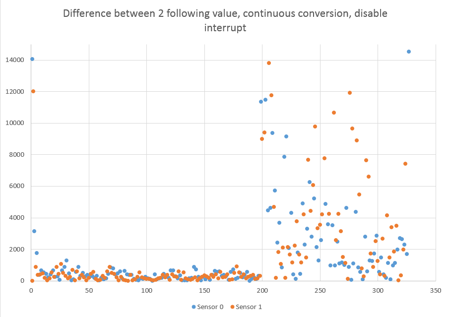
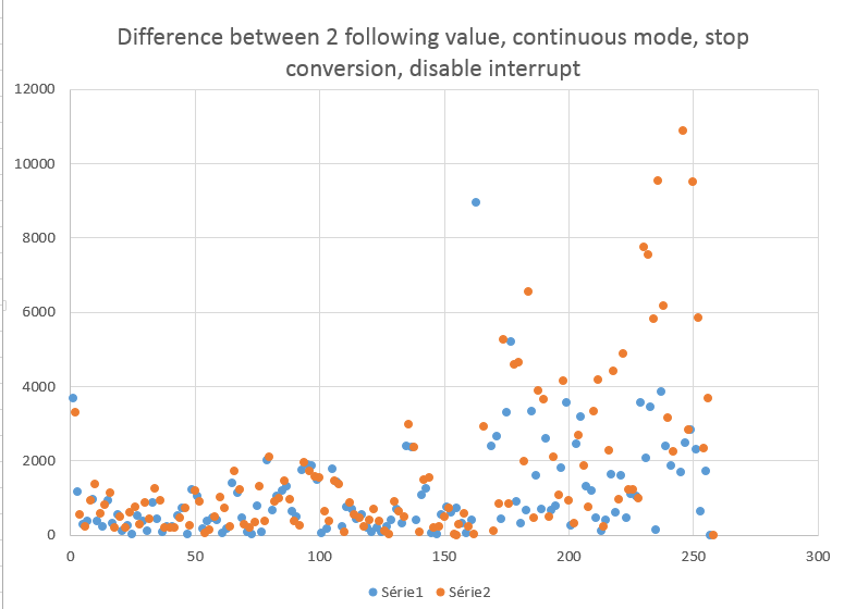
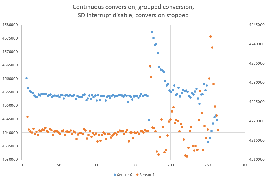
Attach there is 2 graph that show result using stop conversion or disable interrupt, to show the accuracy the first  ~200 values are when there is no movement and the following one are when there is movement. When there is no movement, the difference between 2 following value should be low and when there is movement the different should be higher. (the x axis is the conversion number and the y axis is the value of the adc. when there is 2  axis the one on the left is for sensor 0 and on the right sensor 1.
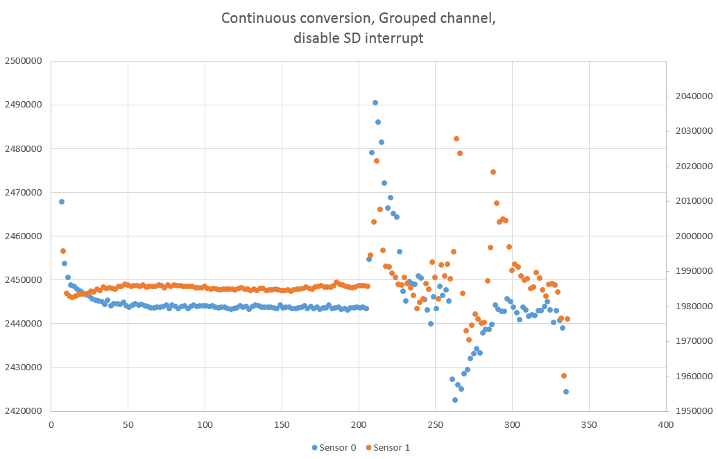
And here is my code. (I used example code in order to get directly the startup code because when I try to had to my code low_level_init.c it was stack on the CRC control.

#include "driverlib.h"
#include <stdlib.h>

#define Num_of_Results 4

/* Arrays to store SD24 conversion results */
uint32_t Ch0results[Num_of_Results];
uint32_t Ch1results[Num_of_Results];
uint32_t Ch2results[Num_of_Results];
uint32_t Ch3results[Num_of_Results];


//mean result of each sensors
uint32_t downLeftResultMean;
uint32_t upLeftResultMean;
uint32_t upRightResultMean;
uint32_t downRightResultMean;

//array of the 4 sensor (down left => 0, down right => 1, up left => 2, up right => 3
uint32_t diffSensor[4];


uint16_t index = 0;

void main(void) {

eaceP1DIR = 0xFF; // set all pin as output direction to save power
P1OUT = 0x00;
P2DIR = 0xFF; //set all pin as output direction to save power
P2OUT = 0x00;

CSCTL0 = DCOR;

// Stop WDT
WDTCTL = WDTPW | WDTHOLD; // Stop Watchdog Timer

// Configure interval to ACLK / 32k ~= 1s
WDTCTL = WDT_ADLY_1000;
WDT_resetTimer(WDT_BASE);

// Internal ref
SD24_init(SD24_BASE, SD24_REF_INTERNAL);

//Group with Channel 0

SD24CCTL0 = SD24DF | SD24GRP; //continuous mode, grouped, over sampling 256, format 2nd complement
SD24INCTL0 = SD24INCH_0 | SD24GAIN_1; // 4th sample interrupt, gain 4, differential pair input

//Group with Channel 1
SD24CCTL1 = SD24DF | SD24GRP; //continuous mode, grouped, over sampling 256, format 2nd complement
SD24INCTL1 = SD24INCH_1 | SD24GAIN_1; // 4th sample interrupt, gain 4, differential pair input

//Group with Channel 2
SD24CCTL2 = SD24DF | SD24GRP; //continuous mode, grouped, over sampling 256, format 2nd complement
SD24INCTL2 = SD24INCH_2 | SD24GAIN_1; // 4th sample interrupt, gain 4, differential pair input


// Enable interrupt
SD24CCTL3 = SD24DF | SD24IE; //continuous mode, grouped, over sampling 256, format 2nd complement
SD24INCTL3 = SD24INCH_3 | SD24GAIN_1; // 4th sample interrupt, gain 4, differential pair input


// Configure MCLK, SMCLK = ~1MHz
CSCTL1 |= DIVM__16 | DIVS__16;

WDTCTL = WDT_ADLY_250;

// Start the WDT and enter LPM3 with interrupts enabled
SFR_clearInterrupt(SFR_WATCHDOG_INTERRUPT);
SFR_enableInterrupt(SFR_WATCHDOG_INTERRUPT);
WDT_start(WDT_BASE);

__bis_SR_register(LPM3_bits | GIE);

}

#if defined(__TI_COMPILER_VERSION__) || defined(__IAR_SYSTEMS_ICC__)
#pragma vector=SD24_VECTOR
__interrupt void SD24_ISR(void) {
#elif defined(__GNUC__)
void __attribute__ ((interrupt(SD24_VECTOR))) SD24_ISR(void)
#else
#error Compiler not supported!
#endif
switch(__even_in_range(SD24IV,SD24IV_SD24MEM3))
{
case SD24IV_NONE: break;
case SD24IV_SD24OVIFG: break;
case SD24IV_SD24MEM0: break;
case SD24IV_SD24MEM1: break;
case SD24IV_SD24MEM2: break;
case SD24IV_SD24MEM3:
// Save CH2 results (clears IFG)
Ch0results[index] = SD24_getResults(SD24_BASE, SD24_CONVERTER_0)>>2;
Ch1results[index] = SD24_getResults(SD24_BASE, SD24_CONVERTER_1)>>2;
Ch2results[index] = SD24_getResults(SD24_BASE, SD24_CONVERTER_2)>>2;
Ch3results[index] = SD24_getResults(SD24_BASE, SD24_CONVERTER_3)>>2;
index++;

break;

default: break;
}

if(index == Num_of_Results)
{
index = 0;
//When 4 conversion are done compute the mean of the four conversion
downLeftResultMean = (Ch0results[0] + Ch0results[1] + Ch0results[2] + Ch0results[3]); //downLeftResultMean
upLeftResultMean = (Ch1results[0])+(Ch1results[1])+(Ch1results[2])+(Ch1results[3]); //upLeftResultMean
upRightResultMean = (Ch2results[0])+(Ch2results[1])+(Ch2results[2])+(Ch2results[3]); //upRightResultMean
downRightResultMean = (Ch3results[0])+(Ch3results[1])+(Ch3results[2])+(Ch3results[3]); //downRightResultMean


//SD24CCTL3 &= ~SD24SC;


SD24CCTL3 &= ~SD24IE;

__bic_SR_register_on_exit(LPM0_bits); // Return to LPM3 after reti
}

}

#if defined(__TI_COMPILER_VERSION__) || defined(__IAR_SYSTEMS_ICC__)
#pragma vector=WDT_VECTOR
__interrupt
#elif defined(__GNUC__)
__attribute__((interrupt(WDT_VECTOR)))
#endif
void WDT_ISR(void)
{

SD24CCTL3 |= SD24SC | SD24IE;

__bis_SR_register_on_exit(LPM0_bits | GIE);

}

  • Hi Chloe,

    Sorry for the delay - we had a holiday in the US end of last week. I'm working to loop in an SD24 expert to help with your question - thanks for your patience.

    -Katie
  • Hello Katie,

    Thanks for your reply, no problem for the delay.

    I discover the reason why the mean value obtain when only interruption is disable (ID) is different from when stopping conversion (SC). In fact using SC the voltage at the A1-, A2- etc change according to the gain (when the gain is 2 it multiply the voltage of the Ax- by 2 compare to gain 1) and when only ID is used the voltage of the Ax- is constant. Here I used the same gain for both way but even with that the voltage is different using ID or SC. I still don't know why it does that.

    I suppose that the difference of accuracy of the results in the 2 way can also be due to that.

    If you have an explanation of those differences, I am still interested to know more.

    Best regards

    Chloé

    PS: ID = interrupt disable, SC = stop conversion

  • Could you show ADC input circuit? Specify signal source, it's impedance?
  • Chloe,

    As Katie said before, sorry for the delay in response. I am just now catching up following the holiday.

    My first thought when encountering this post is that some difference should be expected, due to the nature of delta-sigma converters and their continuous nature. As you probably know, the delta-sigma architecture is built on oversampling of data, and using this extra "context" to drive a control loop like circuit to achieve high resolution on low frequency signals.

    That being said, the difference should not be this extreme. You had stated that you took data where both signals were at the same gain, do you have similar plots to share for this updated data?

    Another thing I noticed quickly looking through your code is that you are entering LPM3 in your main loop, but then waking up and re-entering LMP0 in your ISRs. Is this intentional, or is this a mistake?

    A second thing to try in your code is to simply change your converters over to single conversions rather than continuous and starting/stopping interrupts with the interrupt enable. In actuality, it looks like your code doesn't actually stop the conversions, just the interrupts from the conversions, and the extra start conditions (although they shouldn't) could be causing a bit of unexpected noise in the input circuitry. Have you already attempted the same code, but using just a single conversion?

    I would suggest that you fix the two issues I mention in your code and test it again. Please let me know if this continues to be an issue.
  • Dear Ilmars,

    Sorry for the delay, I was trying some tests.

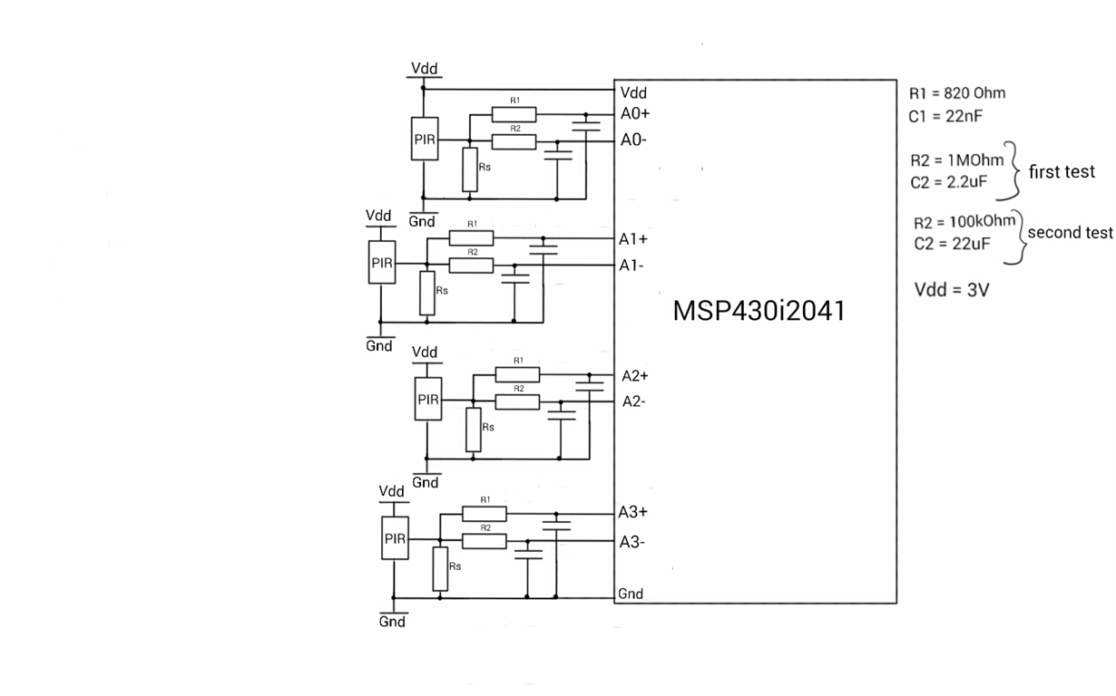
    Here is my circuit. I use the development board MSP-TS430RHB32A therefore all the recommend capacitor and resistor that are placed on the development board are not shown on the schematics. When I first wrote the question I used R2 = 1MOhm, C2 = 2.2 uF but now I am using R2 = 100 kOhm and C2 = 22 uF to decrease the differential offset value.

    Thanks for the help

    Best regards

    Chloé

  • Dear Mr Witt,

    Thanks for your help!

    Sorry for the delay, I was trying some tests.

    Data shown on my first post are both at the same gain (gain 1).

    For the LPM mode I want to pass from LPM0 to LPM3 without waking up the device completely, but I am not sure I am doing it right. In fact I correct at the end of LPM0 ISR I directly go into LPM3 instead of “bic… lpm0”.

    You were right for the extra starting instruction. It was the cause of the multiplication of the minus input. Without the extra start, the minus input is at the same voltage as the continuous conversion using stop conversion or single conversion.

    Finding that, in continuous conversion with disable interrupt and the extra start, I have the voltage changing I found that my dimensioning of my low pass filter R2 and C2 was not so well dimensioned because the differential offset was too high.

    I did try the single conversion. You can find attached the results using all possible configurations and my code for each of them. On the results the A0 is with the new dimensioning of the minus input low pass filter and A1 with the old one. The continuous conversion using interrupt disable are both (A0, A1) with new dimension for R2 and C2. The continuous conversion, not grouped with mean value doesn’t show very good result. I used another code because with this one I had only 0 result in log break point on IAR but when I use simple break point I can see the value wants is not 0. I will not use this configuration therefore it is not very important.

    Now I have more or less the same result for each configuration, I still have problem of coupling. In the attached file (single conversion, coupling test) showing difference value of 2 following value, you can see that when I move in front of another PIR sensor the other sensor have higher voltage. I don’t know if it is a problem of the circuit or if it is due of the microcontroller coding. When I use “not grouped” configuration it is less visible compare to group conversion. Do you know if it could be caused by the microcontroller?

    Thanks very much for your help

    Best regards

    Chloé

    #include "driverlib.h"
    #include <stdlib.h>

    #define STOP_CONV
    //#define SINGLE_CONV
    //#define NOT_GROUPED
    #define MEAN_MODE

    #define Num_of_Results 4

    /* Arrays to store SD24 conversion results */
    uint32_t Ch0results[Num_of_Results];
    uint32_t Ch1results[Num_of_Results];
    uint32_t Ch2results[Num_of_Results];
    uint32_t Ch3results[Num_of_Results];


    //mean result of each sensors
    uint32_t downLeftResultMean;
    uint32_t upLeftResultMean;
    uint32_t upRightResultMean;
    uint32_t downRightResultMean;

    //array of the 4 sensor (down left => 0, down right => 1, up left => 2, up right => 3
    uint32_t diffSensor[4];
    uint16_t channelNb = 0;


    uint16_t index = 0;

    void main(void) {

    P1DIR = 0xFF; // set all pin as output direction to save power
    P1OUT = 0x00;
    P2DIR = 0xFF; //set all pin as output direction to save power
    P2OUT = 0x00;

    CSCTL0 = DCOR;

    // Stop WDT
    WDTCTL = WDTPW | WDTHOLD; // Stop Watchdog Timer

    // Configure interval to ACLK / 32k ~= 1s
    WDTCTL = WDT_ADLY_1000;
    WDT_resetTimer(WDT_BASE);

    // Internal ref
    SD24_init(SD24_BASE, SD24_REF_INTERNAL);

    //Group with Channel 0
    SD24CCTL0 = SD24DF; //continuous mode, grouped, over sampling 256, format 2nd complement
    SD24INCTL0 = SD24INCH_0 | SD24GAIN_1; // 4th sample interrupt, gain 4, differential pair input

    //Group with Channel 1
    SD24CCTL1 = SD24DF; //continuous mode, grouped, over sampling 256, format 2nd complement
    SD24INCTL1 = SD24INCH_1 | SD24GAIN_1; // 4th sample interrupt, gain 4, differential pair input

    //Group with Channel 2
    SD24CCTL2 = SD24DF; //continuous mode, grouped, over sampling 256, format 2nd complement
    SD24INCTL2 = SD24INCH_2 | SD24GAIN_1; // 4th sample interrupt, gain 4, differential pair input


    // Enable interrupt
    SD24CCTL3 = SD24DF; //continuous mode, grouped, over sampling 256, format 2nd complement
    SD24INCTL3 = SD24INCH_3 | SD24GAIN_1; // 4th sample interrupt, gain 4, differential pair input

    #ifdef SINGLE_CONV
    SD24CCTL0 |= SD24SNGL;
    SD24CCTL1 |= SD24SNGL;
    SD24CCTL2 |= SD24SNGL;
    SD24CCTL3 |= SD24SNGL;
    #endif

    #ifdef NOT_GROUPED
    SD24CCTL0 |= SD24IE;
    SD24CCTL1 |= SD24IE;
    SD24CCTL2 |= SD24IE;
    SD24CCTL3 |= SD24IE;
    #else
    SD24CCTL0 |= SD24GRP;
    SD24CCTL1 |= SD24GRP;
    SD24CCTL2 |= SD24GRP;
    SD24CCTL3 |= SD24IE;
    #endif

    // Configure MCLK, SMCLK = ~1MHz
    CSCTL1 |= DIVM__16 | DIVS__16;

    WDTCTL = WDT_ADLY_250;

    // Start the WDT and enter LPM3 with interrupts enabled
    SFR_clearInterrupt(SFR_WATCHDOG_INTERRUPT);
    SFR_enableInterrupt(SFR_WATCHDOG_INTERRUPT);
    WDT_start(WDT_BASE);

    __bis_SR_register(LPM3_bits | GIE);

    }

    #if defined(__TI_COMPILER_VERSION__) || defined(__IAR_SYSTEMS_ICC__)
    #pragma vector=SD24_VECTOR
    __interrupt void SD24_ISR(void) {
    #elif defined(__GNUC__)
    void __attribute__ ((interrupt(SD24_VECTOR))) SD24_ISR(void)
    #else
    #error Compiler not supported!
    #endif

    #ifdef NOT_GROUPED
    #ifdef SINGLE_CONV
    switch(__even_in_range(SD24IV,SD24IV_SD24MEM0))
    {
    case SD24IV_NONE: break;
    case SD24IV_SD24OVIFG: break;
    case SD24IV_SD24MEM0:
    if(channelNb == 0){
    // Save CH0 results (clears IFG)
    #ifdef MEAN_MODE
    Ch0results[index] = SD24_getResults(SD24_BASE, SD24_CONVERTER_0)>>2;
    #else
    downLeftResultMean = SD24_getResults(SD24_BASE, SD24_CONVERTER_0);//>>2;Ch0results[index]
    #endif
    channelNb++;

    }
    break;
    case SD24IV_SD24MEM1:break;
    case SD24IV_SD24MEM2:break;
    case SD24IV_SD24MEM3:break;
    default: break;
    }
    switch(__even_in_range(SD24IV,SD24IV_SD24MEM1))
    {
    case SD24IV_NONE: break;
    case SD24IV_SD24OVIFG: break;
    case SD24IV_SD24MEM0: break;
    case SD24IV_SD24MEM1:
    if(channelNb == 1){
    #ifdef MEAN_MODE
    Ch1results[index] = SD24_getResults(SD24_BASE, SD24_CONVERTER_1)>>2;
    #else
    // Save CH1 results (clears IFG)
    upLeftResultMean = SD24_getResults(SD24_BASE, SD24_CONVERTER_1);//>>2;Ch1results[index]
    #endif
    channelNb++;
    }
    break;
    case SD24IV_SD24MEM2: break;
    case SD24IV_SD24MEM3: break;
    default: break;
    }
    switch(__even_in_range(SD24IV,SD24IV_SD24MEM2))
    {
    case SD24IV_NONE: break;
    case SD24IV_SD24OVIFG: break;
    case SD24IV_SD24MEM0: break;
    case SD24IV_SD24MEM1: break;
    case SD24IV_SD24MEM2:
    if(channelNb == 2){
    #ifdef MEAN_MODE
    Ch2results[index] = SD24_getResults(SD24_BASE, SD24_CONVERTER_2)>>2;
    #else
    // Save CH2 results (clears IFG)
    upRightResultMean = SD24_getResults(SD24_BASE, SD24_CONVERTER_2);//>>2;Ch2results[index]
    #endif
    channelNb++;
    }
    break;
    case SD24IV_SD24MEM3:break;
    default: break;
    }
    switch(__even_in_range(SD24IV,SD24IV_SD24MEM3))
    {
    case SD24IV_NONE: break;
    case SD24IV_SD24OVIFG: break;
    case SD24IV_SD24MEM0:break;
    case SD24IV_SD24MEM1:break;
    case SD24IV_SD24MEM2:break;
    case SD24IV_SD24MEM3:
    if(channelNb == 3){
    // Save CH2 results (clears IFG)
    #ifdef MEAN_MODE
    Ch3results[index] = SD24_getResults(SD24_BASE, SD24_CONVERTER_3)>>2;
    #else
    downRightResultMean = SD24_getResults(SD24_BASE, SD24_CONVERTER_3);//>>2;Ch3results[index]
    #endif
    channelNb=0;
    index++;
    }
    break;
    default: break;
    }
    #else
    switch(__even_in_range(SD24IV,SD24IV_SD24MEM0))
    {
    case SD24IV_NONE: break;
    case SD24IV_SD24OVIFG: break;
    case SD24IV_SD24MEM0:
    if(channelNb == 0){
    // Save CH0 results (clears IFG)
    #ifdef MEAN_MODE
    Ch0results[index] = SD24_getResults(SD24_BASE, SD24_CONVERTER_0)>>2;
    #else
    downLeftResultMean = SD24_getResults(SD24_BASE, SD24_CONVERTER_0);//>>2;Ch0results[index]
    #endif
    channelNb++;
    break;
    }

    case SD24IV_SD24MEM1:
    if(channelNb == 1){
    #ifdef MEAN_MODE
    Ch1results[index] = SD24_getResults(SD24_BASE, SD24_CONVERTER_1)>>2;
    #else
    // Save CH1 results (clears IFG)
    upLeftResultMean = SD24_getResults(SD24_BASE, SD24_CONVERTER_1);//>>2;Ch1results[index]
    #endif
    channelNb++;
    break;
    }

    case SD24IV_SD24MEM2:
    if(channelNb == 2){
    #ifdef MEAN_MODE
    Ch2results[index] = SD24_getResults(SD24_BASE, SD24_CONVERTER_2)>>2;
    #else
    // Save CH2 results (clears IFG)
    upRightResultMean = SD24_getResults(SD24_BASE, SD24_CONVERTER_2);//>>2;Ch2results[index]
    #endif
    channelNb++;
    break;
    }

    case SD24IV_SD24MEM3:
    if(channelNb == 3){
    // Save CH2 results (clears IFG)
    #ifdef MEAN_MODE
    Ch3results[index] = SD24_getResults(SD24_BASE, SD24_CONVERTER_3)>>2;
    #else
    downRightResultMean = SD24_getResults(SD24_BASE, SD24_CONVERTER_3);//>>2;Ch3results[index]
    #endif
    channelNb=0;
    index++;
    }
    break;
    default: break;
    }

    #endif
    #else
    switch(__even_in_range(SD24IV,SD24IV_SD24MEM3))
    {
    case SD24IV_NONE: break;
    case SD24IV_SD24OVIFG: break;
    case SD24IV_SD24MEM0: break;
    case SD24IV_SD24MEM1: break;
    case SD24IV_SD24MEM2: break;
    case SD24IV_SD24MEM3:
    // Save CH2 results (clears IFG)
    #ifdef MEAN_MODE
    Ch0results[index] = SD24_getResults(SD24_BASE, SD24_CONVERTER_0)>>2;
    Ch1results[index] = SD24_getResults(SD24_BASE, SD24_CONVERTER_1)>>2;
    Ch2results[index] = SD24_getResults(SD24_BASE, SD24_CONVERTER_2)>>2;
    Ch3results[index] = SD24_getResults(SD24_BASE, SD24_CONVERTER_3)>>2;
    #else
    downLeftResultMean = SD24_getResults(SD24_BASE, SD24_CONVERTER_0);
    upLeftResultMean = SD24_getResults(SD24_BASE, SD24_CONVERTER_1);
    upRightResultMean = SD24_getResults(SD24_BASE, SD24_CONVERTER_2);
    downRightResultMean = SD24_getResults(SD24_BASE, SD24_CONVERTER_3);
    #endif
    index++;

    break;

    default: break;
    }
    #endif
    #ifdef MEAN_MODE
    if(index == Num_of_Results)
    {
    index = 0;
    //When 4 conversion are done compute the mean of the four conversion
    downLeftResultMean = (Ch0results[0] + Ch0results[1] + Ch0results[2] + Ch0results[3]); //downLeftResultMean
    upLeftResultMean = (Ch1results[0])+(Ch1results[1])+(Ch1results[2])+(Ch1results[3]); //upLeftResultMean
    upRightResultMean = (Ch2results[0])+(Ch2results[1])+(Ch2results[2])+(Ch2results[3]); //upRightResultMean
    downRightResultMean = (Ch3results[0])+(Ch3results[1])+(Ch3results[2])+(Ch3results[3]); //downRightResultMean

    #else

    if (index > 0)
    {
    index = 0;
    #endif


    #ifndef NOT_GROUPED
    #ifdef STOP_CONV
    SD24CCTL3 &= ~SD24SC;
    #endif

    SD24CCTL3 &= ~SD24IE;
    #else

    SD24CCTL0 &= ~SD24IE;
    SD24CCTL1 &= ~SD24IE;
    SD24CCTL2 &= ~SD24IE;
    SD24CCTL3 &= ~SD24IE;

    #ifdef STOP_CONV
    SD24CCTL0 &= ~SD24SC;
    SD24CCTL1 &= ~SD24SC;
    SD24CCTL2 &= ~SD24SC;
    SD24CCTL3 &= ~SD24SC;
    #endif
    #endif

    __bis_SR_register_on_exit(LPM3_bits | GIE); // Return to LPM3 after reti
    }
    #ifdef SINGLE_CONV
    else{
    #ifdef NOT_GROUPED
    SD24CCTL0 |= SD24IE | SD24SC;
    SD24CCTL1 |= SD24IE | SD24SC;
    SD24CCTL2 |= SD24IE | SD24SC;
    SD24CCTL3 |= SD24IE | SD24SC;
    #else
    SD24CCTL3 |= SD24SC | SD24IE;
    #endif
    }
    #endif
    }

    #if defined(__TI_COMPILER_VERSION__) || defined(__IAR_SYSTEMS_ICC__)
    #pragma vector=WDT_VECTOR
    __interrupt
    #elif defined(__GNUC__)
    __attribute__((interrupt(WDT_VECTOR)))
    #endif
    void WDT_ISR(void)
    {
    #ifdef NOT_GROUPED
    SD24CCTL0 |= SD24IE | SD24SC;
    SD24CCTL1 |= SD24IE | SD24SC;
    SD24CCTL2 |= SD24IE | SD24SC;
    SD24CCTL3 |= SD24IE | SD24SC;
    #else
    SD24CCTL3 |= SD24SC | SD24IE;
    #endif


    __bis_SR_register_on_exit(LPM0_bits | GIE);

    }

    PS: I did not manage to insert my results file, is is possible to link a file in pdf and keep it in pdf? or can I send it to you by email?

**Attention** This is a public forum