This thread has been locked.

If you have a related question, please click the "Ask a related question" button in the top right corner. The newly created question will be automatically linked to this question.

Unable to achieve the LPM3 low power consumption from the datasheet

Other Parts Discussed in Thread: MSP430FR5969

Hello,

I would like to develop a wireless sensor node with the Launchpad MSP430FR5969. The node will sleep most of the time and I only need to interrupt it once an hour, while the precise timing is not important at all. I thought that using the RTC interrupt would be the way to go. According to the datasheet, I could put it into the LPM3.5 sleep mode which should consume about 0.5μA, which sounds great. However, I am not able to achieve such a low consumption.

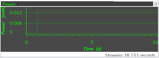
I opened the example msp430fr59xx_lpm3-5_01.c in the CCS6.1.1.00022, ran it in the debug mode, analyzed with the Energy Trace and it measured the mean current of 3.4μA. I expected something around those 0.5μA.

(The voltage for the Energy Trace was set to 3V)

Then I tried the example msp430fr59xx_lpm4.c which runs in the LPM4 mode, but again the Energy Trace measured the very same mean current of 3.4μA. Again I expected something around 0.5μA or even lower.


Maybe I am doing something wrong, I am really new to the MSP430 world. Before I worked with the Arduino (Atmega328p).

Here is the datasheet mentioning the consumption of only 0.2 - 1.7μA:
www.ti.com/.../specifications

And here is the code of the LPM4 example (msp430fr59xx_lpm4.c):

#include <msp430.h>

int main(void)
{
  WDTCTL = WDTPW | WDTHOLD;                 // Stop WDT

  // Configure GPIO
  P1OUT = 0;
  P1DIR = 0xFF;

  P2OUT = 0;
  P2DIR = 0xFF;

  P3OUT = 0;
  P3DIR = 0xFF;

  P4OUT = 0;
  P4DIR = 0xFF;

  PJOUT = 0;
  PJDIR = 0xFFFF;

  // Disable the GPIO power-on default high-impedance mode to activate
  // previously configured port settings
  PM5CTL0 &= ~LOCKLPM5;

  // Clock System Setup
  CSCTL0_H = CSKEY >> 8;                    // Unlock CS registers
  CSCTL1 = DCOFSEL_6;                       // Set DCO to 8MHz
  CSCTL2 = SELA__VLOCLK | SELS__DCOCLK | SELM__DCOCLK;  // Set SMCLK = MCLK = DCO
                                            // ACLK = VLOCLK
  CSCTL3 = DIVA__1 | DIVS__1 | DIVM__1;     // set all dividers
  CSCTL0_H = 0;                             // Lock CS registers

  __bis_SR_register(LPM4_bits);
  __no_operation();                         // For debugger
}

I would be really grateful for any hint.

Thanks a lot,
Michal

  • Did you remove all the jumpers? A 47K pull-up on some line could be the reason, as you do hard pull down on all pins.

    eZ-FET Isolation Jumper Block
    Reasons to open these connections: • To remove any and all influence from the eZ-FET emulator for high accuracy target power measurements

  • Hello Michal,

    for proper LPM3 or LPM4 operation you have to clear the oscillator-fault-flag, otherwise the oscillator-fault logic is active.

    Try to clear the LFXTOFFG and HFTXTOFFG-Bits in CSCTL5 register and the global oscillator fault flag OFIFG in SFR1 register.

    You can use the following code   

        while (SFRIFG1 & OFIFG)   // is global oscillator fault flag set?
        {
         CSCTL5 &= ~(LFXTOFFG+HFXTOFFG);  // try to clear LF and HF oscillator fault flags

         SFRIFG1 &= ~OFIFG;   // try to clear global oscillator fault flag
        }

    Best regards,

    Michael

  • Thank you both guys a lot for your quick response!

    Tony, you were right. removing the jumpers was indeed the correct solution. I just had to remove the RXD, TXD, RST and TST jumpers from the J13 block (RXD and TXD seem to be the ones causing the issue). Then the Energy Trace measured only 0.1μA in both examples (LPM3.5 and LPM4), which is maybe even suspiciously low :o), but everything worked as expected.

    Michael, in the msp430fr59xx_lpm3-5_01.c example, there is a similar code as you suggested:

    CSCTL4 &= ~LFXTOFF;                       // Enable LFXT1
    do
    {
      CSCTL5 &= ~LFXTOFFG;                    // Clear XT1 fault flag
      SFRIFG1 &= ~OFIFG;
    } while (SFRIFG1&OFIFG);                  // Test oscillator fault flag
    

    ...but they only clear the LFXTOFFG, not the HFTXTOFFG. But the MSP430FR5969 seems not to have the HFXT on board according to this post: https://e2e.ti.com/support/microcontrollers/msp430/f/166/p/408147/1448028#1448028

    Thank you both a lot!
    Michal

  • You may not have to remove the jumper, if it turns out that it's due to uart Is using pull-ups, just put corresponding pin in pull-up too.
    This is something you have to make sure a custom made pcb board, that every pin is at optimal mode to save power while it's not used.
  • That would be great, Tony! However, I was not able to make it working without physically removing the jumpers. I tried this code in the LPM4 example:

    P2OUT = 0;
    P2DIR = 0xFF;
    P2REN |= (BIT5 + BIT6);
    

    The pins P2.5, P2.6 are TXD and RXD. When I measured the voltage of the P2.5 and P2.6 pins, I got 16mV, but when I removed the jumpers, I got 0mV. Don't you know what I am missing here?

    Thank you a lot for your help,
    Michal

  • You need to do this with to get Pull-up. P2DIR should still be left at 0x00.

    P2OUT |= (BIT5 + BIT6);
    P2REN |= (BIT5 + BIT6);

  • Thank's Tony, I have tried that, but still observing the same higher drain as before. Maybe it is really not possible to do it on the software side? Because the Launchpad's manual also mentions disconnecting the jumpers manually for low-power measurements.

**Attention** This is a public forum