This thread has been locked.

If you have a related question, please click the "Ask a related question" button in the top right corner. The newly created question will be automatically linked to this question.

High Speed Pulse Counting with MSP432?

Other Parts Discussed in Thread: MSPWARE, MSP430F5172, ALLIGATOR

I have a project where I will need to count pulses with widths of 9ns. I saw this:

"The MSP430F51x1/51x2 have two TimerD units supporting up to 256MHz input clock..."

and I looked through the MSP432 and didn't see that it has a similar capability. Are the MSP430F51x1/51x2 the only ones capable of 256MHz operation?

  • George,

    9 ns is equivalent to 111 MHz which is far too fast to be counted by any MSP devices. Even the TimerD peripheral which exists solely on F51x1/F51x2 devices is only capable of generating pulses up to 256 MHz, not counting them. You will need to use a separate device to count the pulses and then transmit this information in packets to the MSP432.

    Regards,
    Ryan
  • Ryan Brown1 said:


    9 ns is equivalent to 111 MHz which is far too fast to be counted by any MSP devices. Even the TimerD peripheral which exists solely on F51x1/F51x2 devices is only capable of generating pulses up to 256 MHz, not counting them.

    I was able to measure 48 MHz frequency (TA0CLK and TA1CLK) with 5xx running on 24 MHz MCLK. Didn't try to measure higher frequency.
  • Thanks Ryan for clarifying that, I guess I missed that point about the timer. Any chance you have any suggestions for something that would be able to count at that rate?

  • I do not know of anything from the MSP catalog, this is a question most likely worth asking in a different forum.
  • Ryan Brown1 said:

     
    9 ns is equivalent to 111 MHz which is far too fast to be counted by any MSP devices. Even the TimerD peripheral which exists solely on F51x1/F51x2 devices is only capable of generating pulses up to 256 MHz, not counting them.

    I was reading the datasheet for this family and on page 45 is the "Input Capture and Output Compare Timing" specs and it shows tTD, (Timer_D input capture timing, minimum pulse duration to trigger input capture event) is 4ns typical. So I wonder if your statement is really correct?

  • >I have a project where I will need to count pulses with widths of 9ns.

    As already noted, you can't do it with msp430 alone, however there's simple solution: prescaler. Speed of SN74LV161 seems to match your needs.

  • Interesting idea on using the SN74LV161. We're you thinking of using the A input and then having the MSP430 monitor the RCO pin?

    I'm sorry, but can you clarify what I'm misunderstanding about the F51x1/F51x2? The input capture is specified at 4ns so why wouldn't that work?
  • >Interesting idea on using the SN74LV161. We're you thinking of using the A input and then having the MSP430 monitor the RCO pin?
    Using timer you count pulses divided by prescaler. When stop counting, read state of prescaler using GPIO and obviously state of your timer too.

    >can you clarify what I'm misunderstanding about the F51x1/F51x2? The input capture is specified at 4ns so why wouldn't that work?
    This is just about pulse width of capture input signal. Your application supposedly is about _counting_ impulses, not capturing state of timer which runs from internal clock, right? What you shall be reading is: page 41, "Timer_D input reference clock frequency" which is 25 MHz max.
  • I picked up a board that has a MSP430F5172 on it so I could experiment with Timer_D. I thought maybe I could use this to output a fast pulse for my initial testing. I was looking at the MSPWare code examples and the smallest pulse width example generate ~90ns pulse with the PWM example. I was hoping that perhaps you could help with some small example code that code produce pulses as short as possible. I guess I'm still not quite fully understanding the benefit of the High Resolution Timer.

  • George,

    Have you referenced the Using the MSP430 Timer_D Module in Hi-Resolution Mode Application Report (SLAA601)? It has valuable information on how to set the maximum frequency (256 MHz) and PWM (16 MHz at 50 % duty cycle) for Timer D: www.ti.com/.../slaa601.pdf

    Regards,
    Ryan
  • Hi Ryan,

    Yes, I had looked at that yesterday, and in particular I was concentrating on p19 equation 28. I understand that with the HRT timer you can achieve a maximum PWM frequency of 16MHz (compared to a standard of 12.5MHz) and your maximum resolution is 4ns but to be honest I was a little lost on the configuration of the registers required to experiment with lower duty cycles yielding narrower pulses. I guess I was just a bit surprised given the capability of the HRT that there wasn't just a flat out example to show the maximum it can achieve. Since I program on such an infrequent basis I often struggle getting started!
  • Hi George,

    Take the examples (regulation.c or freerunning.c) from the slaa601.zip package which already initialize Timer D for a clock frequency of 256 MHz and change TD0CCR0 to 16 & TD0CCR1 to 8 to get a 16 MHz PWM with 50% duty cycle.

    Regards,
    Ryan
  • Hi Ryan,

    Yesterday when I looked at that code I already had the PWM examples from MSPWare loaded into CCS. They looked almost the same so I started playing with the TD0CCR1 value to reduce the duty cycle but there was a point when I reduced this value that the PWM would simply stop being generated. I'm sure that means I violated some condition that detailed in the app note but that's when I stopped and decided maybe I'd make a post and see what the experts had to say.

    // Setup Timer_D standard registers
    //
    TD0CCTL1 = OUTMOD_7;					// Reset/Set mode
    TD0CTL0 = TDCLR + MC_1;					// Up mode
    TD0CCR1 = 23;						// Duty cycle
    TD0CCR0 = 44;						// Frequency = 256MHz/(Effective CCR0 + 1) = 256MHz/(47+1) = 5.33 MHz

    Looking at this section of code and Table 7 the maximum frequency when be achieved when TDHM=0 (x8 multiplier)and TDxCL0=1 which yields an effective CCR0=7+1 and a frequency of 32MHz (256MHz/8). Do I have at least this part correct?

    I then would have to reduce TD)CCR1 to get a lower duty cycle but I guess I have to read more about what the limitations are in doing that.

  • I forgot to mention that I did try this combination and you don't get a PWM signal when you change TD0CCR0 to 16 & TD0CCR1 to 8
  • Hi Ryan,

    I hope that you had a good weekend. I spent some more time on this and have made some progress. After going back through the example code, TRM, datasheet, and app note, I've come up with this test code:

    int main(void) {
    
    	//
    	// System Initialization
    	//
    	WDTCTL = WDTPW | WDTHOLD;				// Stop watchdog timer
    
      	//
    	// Setup Port Pins to TD0.1 on P1.7. No port mapping required on these pins
    	//
      	P1SEL |= BIT7;                          // P1.7 options select
      	P1DIR |= BIT7;                          // P1.7 output
    
      	//
    	// Setup Timer_D high-resolution registers - FREE RUNNING MODE (TDHREGEN = 0)
      	// Note: No clock source is required for free running mode
    	//
      //	TD0HCTL1 = CALTDH0CTL1_256;  			// Read the 256Mhz TimerD TLV Data
    		TD0HCTL1 = TDHCLKCR
    						 + TDHCLKR1
    						 + TDHCLKSR0 + TDHCLKSR1 + TDHCLKSR2 + TDHCLKSR3 + TDHCLKSR4
    						 + TDHCLKTRIM6;
      	TD0CTL0 = CNTL_0  						// 16-bit timer
      	      	+ ID_0  						// Divide by 1
      	      	+ MC_0;  						// Halt timer until init is complete
      	TD0CTL1 |= TDCLKM_1;					// TD0 clock = Hi-res local clock
      	TD0HCTL0 = TDHFW 						// Fast wake-up mode.
      	      	+ TDHD_0						// Set divider to 1
     // 	      	+ TDHM_1 						// Multiply by 16 (TDHMx=01), x8 (TDHMx=00)
      	      	+ TDHEAEN						// Enhance accuracy
      	      	+ TDHEN;    					// Enable Hi-Res
      	//
    	// Setup Timer_D standard registers
    	//
      	TD0CCTL1 = OUTMOD_7;					// Reset/Set mode
    	TD0CTL0 = TDCLR + MC_1;					// Up mode
    	TD0CCR1 = 8;							// Duty cycle
    	TD0CCR0 = 15;							// Frequency = 256MHz/(Effective CCR0 + 1) = 256MHz/(47+1) = 5.33 MHz(44)
    
    	//
    	// PWM is running - go to into low power mode
    	//
    	__bis_SR_register(LPM3_bits);  			// Enter LPM3

    It's far from ideal and I'd like to clean it up some but hopefully it will help others. I've mentioned it in other posts but I find that many of the example codes are at times not as helpful as they could be. If you're going to set registers and rely on the default values in the registers you should at least document that you're not setting bits xx because they are already set by default. As an example, the freerunning.c example they used a constant to set TD0HCTL1 which is fine but they didn't bother to detail how they arrived at that value.

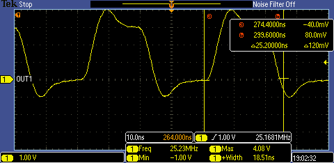
    With the above code you can see the output on a scope that looks like this:

    The scope setup is far from ideal (alligator clips being used) but it does show a ~25ns pulse on P1.7

    From the TRM you can find limitations of the CC values for maximum duty cycle:

    I'm not sure if I can push this any further to try to get a narrower pulse width but it would be nice to see what you can get under the right conditions

  • Hi George,

    I'm glad to see that you were able to make some progress with your code. I am currently trying to loop in the owner of the TimerD application report so that he can look at your comments and provide some more insight.

    Edit: Some feedback from the application report author is as follows: 

    For the input capture question, if you want to get ONE edge captured then it is ~4ns. We have a typical number only since this cannot be ever production tested to this accuracy. We do not have information on the minimum pulse width that can be detected.  About one course clock is required. In other words, for the 16x mode 1/256MHz * 16 = 62.5ns is required and for the 8x mode 1/128MHz * 8 = 62.5ns is required. 

    Regards,
    Ryan

  • Hi George, 

    Can you please elaborate on what you are trying to accomplish? If I understand correctly, you want to test the absolute maximum PWM frequency that you can generate with Timer_D. If this is the case, the maximum PWM frequency is 16MHz. In the document Ryan suggested above (SLAA601) there is a note regarding the maximum frequency of Timer_D operation:

    The only way you can accomplish a PWM frequency higher than 16MHz is by running Timer_D outside the recommended operating conditions. I looked at your code and you are in fact running faster by adjusting the TD0HCTL1 register. 

    MSP430 microcontrollers are designed, characterized and tested to run within the specifications outlined in the respective datasheets. Operating above Recommended Maximum values or below recommended minimum values in general could lead to unexpected results; operating above Absolute Maximum values or below absolute minimum values in the datasheet can cause physical damage to the MSP430 MCU.

    It is true that in some use-cases an MSP430 MCU may operate correctly outside of the specified limits, but performance is not guaranteed and such operations are done at the risk of the user.

    Regarding your note about using CALTDH0CTL1_256 for TD0HCTL1. CALTDH0CLT1_256 is not a constant because it is not the same for all devices. CALTDH0CLT1_256 points to a memory location in the TLV structure in memory that contains device-specific calibration constants. The TLV structure contains calibration values that can be used to improve the measurement capability of various functions. The calibration values available on a given device are shown in the TLV structure of the device-specific data sheet. This is also explained on SLAA601:

    I hope this helps, 

    Damian

  • >The only way you can accomplish a PWM frequency higher than 16MHz is by running Timer_D outside the recommended operating conditions.

    Honestly I don't get it. In datasheet excerpt you are showing us it is clearly said that Timer_D maximum frequency is 256MHz yet you are saying it is 16MHz.

    I am afraid you are mixing high-speed timer reference clock (max 25MHz) with timer local clock generator (max 256MHz) and PWM frequency which also shall reach at least pin toggle frequency of chip, in this case 25 MHz.
  • Ilmars,
    There are two different frequencies: 1) the frequency of Timer_D and the 2) PWM frequency. SLAA601 explains why the maximum frequency of the PWM is not the same as the maximum frequency of Timer_D (or even why it cannot be 25MHz). The maximum frequency of Timer_D is 256MHz, but the maximum frequency of the PWM that can be generated using Timer_D as the input source clock is 16MHz.

    Damian
  • Hi Damian,

    Thanks for taking a look at this. I'll rewind a bit since a lot has been written since I started this thread. I initially read that these parts could achieve 256MHz operation and was enticed at what I could do with that since I was looking for something to count ~10ns wide pulses. I've learned since starting this thread that really you don't get 256MHz operation, only the ability to slice up the PWM frequency in smaller increments than what you can normally achieve.

    I'm still not grasping everything but I'm getting better. I really don't want to be a MSP430 Timer D expert but it seems I'm not smarter than the average bear or you really have to understand a bunch of different aspects before you can fully use the HRT. What I'm just trying to do now is to just benchmark what the minimum pulse width I can achieve for testing. The photon counter I'll ultimately be interfacing to is the one generating 10ns pulses but I don't have one yet and wanted something I could use to simulate it.

    So from what you're saying the fastest PWM is 16MHz which is even lower than the 25MHz that the part can operate at. I understand fully about running parts outside of specifications and don't plan on doing this on a production product. I'm more involved in this now than I wanted to be but I've gone this far so I thought I'd keep going!

    The original freerunning.c code had:

    #define CALTDH0CTL1_256      *((unsigned int *)0x1A36)
    
    ...
    
    TD0HCTL1 = CALTDH0CTL1_256;  			// Read the 256Mhz TimerD TLV Data

    and since I'm not a top notch programmer I completely missed that the define statement was a pointer to a memory location so yesterday I decided to "decode" the value entered in TD0HCTL1 and make sense of what was being changed in the register.

    While I have your attention, why in Table 10 do they have TDHCLKTRIM = 128 when TDHCLKTRIM is only 7 bits in the register and therefor can't be more than 127, setting it to 128 takes 8 bits?

    Thanks,

    George

  • Thanks. I did read mentioned appnote about "high resolution" timer which is not that high resolution after all :)

    >maximum frequency of the PWM that can be generated using Timer_D as the input source clock is 16MHz.
    Sorry? If I don't want to use timer PWM output as the input clock source then what maximum frequency of timer PWM output can be? [just kidding] - I know the answer just want you to doublecheck what you actually said
  • George,
    I am not sure why the value is 128. If I had to guess, I would say that this includes the reserved bit 0 of the TDxHCTL1 register. I sent the question to the folks that maintain datasheets, so hopefully I will have a better answer for you then.

    To elaborate further on CALTDH0CTL1_256, the reason that this is a pointer and not a constant is that the actual value that gets loaded into TD0HCTL1 varies slightly from device to device. TI runs a calibration routine before shipping units that populate the TLV table (a region of non-volatile memory) with the calibration values for each specific device. So, if you do TD0HCTL1 = CALTDH0CTL1_256 for two MSP430F5172 devices, you are very likely to see different values loaded to the register.

    Damian
  • Ilmars,
    There is a fundamental difference between high speed and high resolution. Timer_D does not enable high-speed PWMs but it enables higher resolution steps for generating PWM signals when compared to other MSP430 timers. For instance, Timer_D gives you a duty cycle resolution of 4ns. Also, in free running mode, the TDHCLKTRIMx bits allow you to adjust the frequency of your PWM signal in steps of approximately 1.5%.

    Damian
  • Damian,

    OK, at least that's one thing that isn't clear just to me!

    So I was using the values in the app note to set TD0HCTL1 to try and push the MSP430 a little and I was successful as evidenced by my scope plot. Looking at Table 10 I should , in theory, be able to push the frequency even beyond what I did but I believe that relies on setting TDHCLKTRIM = 128 which I wasn't able to do.

    My goal at this point is to push things on the test bench to try and get as narrow a pulse as possible. Have I achieved this already or is there more than I can do?

    Thanks,
    George
  • George,

    The most you can push the timer is by setting all bits of the register TD0HCTL1 to 0x1. Since bit 0 is reserved and read-only, wrtting 0xFFFE to TD0HCTL1 will give you the absolute fastest configuration. Please note again that this will be running outside of recommended settings.

    Damian

  • Damain,

    0xFFFE is not a valid register setting for TD0HCTL1 because that sets TDHCLKRx to 11b which is reserved. This Clock Range setting greatly impacts the PWM speed and I was able to observe the following with the board that I have:

    • 0x9FFE -> Clock Range=00b ==> ~8.3MHz
    • 0xBFFE -> Clock Range=01b ==> ~14.6MHz
    • 0xDFFE -> Clock Range=10b ==> ~25.2MHz

    This now looks like I'm really starting to push things as the rise and fall times are impacting the pulse width. My setup is far from ideal so with a little hardware tweaking I think that signal could get cleaned up a little and achieve a slightly narrower pulse width.

  • >My setup is far from ideal so with a little hardware tweaking I think that signal could get cleaned up a little and achieve a slightly narrower pulse width.

    To be honest, you are trying to build high speed circuit using low power devices which does not have powerful enough (high current) I/Os that can switch pins fast. BTW initially your aim was measuring pulses, not generating them. Focus is shifted now?

  • I completely understand that what I'm doing is a little outside the box but while I was researching for this project I could not find anything similar to what I wanted to do. I wanted to just see the limits of the MSP430 HRT and document for others since I was already half way into it. I know I appreciate it when people post the details of what they're doing and show actual results. I think this is a good way for people to experiment as they have a known reference to work from.

    Yes, I still need to count 10ns pulses but I would try to use the HRT to simulate the photon detector's output since I don't have one yet. In the final design I'll be using the high speed counter as a scaler prior to the input of the MSP430.

  • George,
    The correct value of TD0HCTL1 for the TRIMx bits is 127. The datasheet needs to be fixed.

    Thanks,
    Damian
  • Damian,

    Thanks for following up on that, do I get a gold star for finding an error?!

    For completeness here's what the scope plot looks like with better connections

    I'd say that's a major improvement, about 3ns tr and a slightly longer tf, not bad at all.

**Attention** This is a public forum