This thread has been locked.

If you have a related question, please click the "Ask a related question" button in the top right corner. The newly created question will be automatically linked to this question.

Reading and Writing to EEPROM using I2C MSP430F6776

Hi All,

Trying to write a byte to memory and then read it back to confirm the EEPROM communication is working.

Tried using the example code...

#include <msp430f6776.h>

unsigned char TXData;
unsigned char TXByteCtr;

void main(void)
{
    WDTCTL = WDTPW | WDTHOLD;                         // Stop WDT

    // Setup P2.5 UCB0SCL, P2.6 UCB0SDA
    P2SEL0 |= BIT5 | BIT6;                             // Set P2.5,P2.6 to UCB0SCL, UCB0SDA

    // Setup eUSCI_B0
    UCB0CTLW0 |= UCSWRST;                             // Enable SW reset
    UCB0CTLW0 |= UCMST | UCMODE_3 | UCSSEL_2;         // I2C Master, use SMCLK

    UCB0BRW_L = 12;                                   // fSCL = SMCLK/12 = ~100kHz
    UCB0BRW_H = 0;
    UCB0I2CSA = 0xA0;                                 // Slave Address is 0A0h
    UCB0CTLW0 &= ~UCSWRST;                            // Clear SW reset, resume operation
    UCB0IE |= UCTXIE0;                                // Enable TX interrupt
    TXData = 0x0A;                                    // Holds TX data

    while (1)
    {
        TXByteCtr = 1;                                // Load TX byte counter

        while (UCB0CTLW0 & UCTXSTP) ;                 // Ensure stop condition got sent
        UCB0CTLW0 |= UCTR | UCTXSTT;                  // I2C TX, start condition

        __bis_SR_register(LPM0_bits | GIE);           // Enter LPM0 w/ interrupts
        __no_operation();                             // Remain in LPM0 until all data
                                                      // is TX'd

        TXData++;                                     // Increment data byte
    }
}

//------------------------------------------------------------------------------
// The USCIAB0_ISR is structured such that it can be used to transmit any
// number of bytes by pre-loading TXByteCtr with the byte count.
//------------------------------------------------------------------------------
// USCI_B0 interrupt service routine
#if defined(__TI_COMPILER_VERSION__) || defined(__IAR_SYSTEMS_ICC__)
#pragma vector = USCI_B0_VECTOR
__interrupt void USCI_B0_ISR(void)
#elif defined(__GNUC__)
void __attribute__ ((interrupt(USCI_B0_VECTOR))) USCI_B0_ISR (void)
#else
#error Compiler not supported!
#endif
{
    switch (__even_in_range(UCB0IV, 30))
    {
        case USCI_NONE: break;                        // No interrupts
        case USCI_I2C_UCALIFG: break;                 // ALIFG
        case USCI_I2C_UCNACKIFG: break;               // NACKIFG
        case USCI_I2C_UCSTTIFG: break;                // STTIFG
        case USCI_I2C_UCSTPIFG: break;                // STPIFG
        case USCI_I2C_UCRXIFG3: break;                // RXIFG3
        case USCI_I2C_UCTXIFG3: break;                // TXIFG3
        case USCI_I2C_UCRXIFG2: break;                // RXIFG2
        case USCI_I2C_UCTXIFG2: break;                // TXIFG2
        case USCI_I2C_UCRXIFG1: break;                // RXIFG1
        case USCI_I2C_UCTXIFG1: break;                // TXIFG1
        case USCI_I2C_UCRXIFG0: break;                // RXIFG0
        case USCI_I2C_UCTXIFG0:                       // TXIFG0
            if (TXByteCtr)                            // Check TX byte counter
            {
                UCB0TXBUF = TXData;                   // Load TX buffer
                TXByteCtr--;                          // Decrement TX byte counter
            }
            else
            {
                UCB0IFG &= ~UCTXIFG;                  // Clear USCI_B0 TX int flag
                UCB0CTL1 |= UCTXSTP;                  // I2C stop condition
                __bic_SR_register_on_exit(LPM0_bits); // Exit LPM0
            }
            break;
        case USCI_I2C_UCBCNTIFG: break;               // CNTIFG
        case USCI_I2C_UCCLTOIFG: break;               // LTOIFG
        case USCI_I2C_UCBIT9IFG: break;               // BIT9IFG
        default: break;
    }
}

The EEPROM is the 24LC02B with slave address 0xA0 I believe.

It just sits in the no_operation()  routine and never interrupts.

Any help is appreciated.

  • What do you see on the I²C pins with an oscilloscope or a logic analyzer?
  • SDA is constantly at VCC and SCL is constantly held at VSS.

  • Even directly after a reset?
  • Yes, I powered off and on and it never went high, even briefly.

    I also tried in debug mode and halting the program before and initialization and it was low there also.

  • When idle, both lines should be high. Try adding a long delay at the beginning.

    BTW: how exactly did you connect the EEPROM?

  • I added a 1 second delay before any initialization with no luck.

    PINOUT is follows:
    1. SCL
    2. GND
    3. SDA
    4. VCC
    5. Word Protect (tied to GND for normal operation)

    The code to date is as follows:

    #include <msp430f6776.h>
    
    unsigned char TXData;
    unsigned char TXByteCtr;
    
    void main(void)
    {
      __delay_cycles(1000000);
        WDTCTL = WDTPW | WDTHOLD;                         // Stop WDT
    
        // Setup P2.5 UCB0SCL, P2.6 UCB0SDA
        P2SEL0 |= BIT5 | BIT6;                             // Set P2.5,P2.6 to UCB0SCL, UCB0SDA
    
        // Setup eUSCI_B0
        UCB0CTLW0 |= UCSWRST;                             // Enable SW reset
        UCB0CTLW0 |= UCMST | UCMODE_3 | UCSSEL__SMCLK;    // I2C Master, use SMCLK
    
        UCB0BRW_L = 10;                                   // fSCL = SMCLK/12 = ~100kHz
        UCB0BRW_H = 0;
        UCB0I2CSA = 0xA0;                                 // Slave Address is 0A0h
        UCB0CTLW0 &= ~UCSWRST;                            // Clear SW reset, resume operation
        UCB0IE |= UCTXIE0;                                // Enable TX interrupt
        TXData = 0x01;                                    // Holds TX data
    
        while (1)
        {
            TXByteCtr = 8;                                // Load TX byte counter
    
            while (UCB0CTLW0 & UCTXSTP) ;                 // Ensure stop condition got sent
            UCB0CTLW0 |= UCTR | UCTXSTT;                  // I2C TX, start condition
    
            
            __bis_SR_register(LPM0_bits | GIE);           // Enter LPM0 w/ interrupts
            __no_operation();                             // Remain in LPM0 until all data
                                                          // is TX'd
    
            TXData++;                                     // Increment data byte
        }
    }
    
    //------------------------------------------------------------------------------
    // The USCIAB0_ISR is structured such that it can be used to transmit any
    // number of bytes by pre-loading TXByteCtr with the byte count.
    //------------------------------------------------------------------------------
    // USCI_B0 interrupt service routine
    //#if defined(__TI_COMPILER_VERSION__) || defined(__IAR_SYSTEMS_ICC__)
    #pragma vector = USCI_B0_VECTOR
    __interrupt void USCI_B0_ISR(void)
    /*#elif defined(__GNUC__)
    void __attribute__ ((interrupt(USCI_B0_VECTOR))) USCI_B0_ISR (void)
    #else
    #error Compiler not supported!
    #endif*/
    {
        switch (__even_in_range(UCB0IV, 30))
        {
            case USCI_NONE: break;                        // No interrupts
            case USCI_I2C_UCALIFG: break;                 // ALIFG
            case USCI_I2C_UCNACKIFG: break;               // NACKIFG
            case USCI_I2C_UCSTTIFG: break;                // STTIFG
            case USCI_I2C_UCSTPIFG: break;                // STPIFG
            case USCI_I2C_UCRXIFG3: break;                // RXIFG3
            case USCI_I2C_UCTXIFG3: break;                // TXIFG3
            case USCI_I2C_UCRXIFG2: break;                // RXIFG2
            case USCI_I2C_UCTXIFG2: break;                // TXIFG2
            case USCI_I2C_UCRXIFG1: break;                // RXIFG1
            case USCI_I2C_UCTXIFG1: break;                // TXIFG1
            case USCI_I2C_UCRXIFG0: break;                // RXIFG0
            case USCI_I2C_UCTXIFG0:                       // TXIFG0
                if (TXByteCtr)                            // Check TX byte counter
                {
                    UCB0TXBUF = TXData;                   // Load TX buffer
                    TXByteCtr--;                          // Decrement TX byte counter
                }
                else
                {
                    UCB0IFG &= ~UCTXIFG;                  // Clear USCI_B0 TX int flag
                    UCB0CTL1 |= UCTXSTP;                  // I2C stop condition
                    __bic_SR_register_on_exit(LPM0_bits); // Exit LPM0
                }
                break;
            case USCI_I2C_UCBCNTIFG: break;               // CNTIFG
            case USCI_I2C_UCCLTOIFG: break;               // LTOIFG
            case USCI_I2C_UCBIT9IFG: break;               // BIT9IFG
            default: break;
        }
    }
    

  •     __delay_cycles(1000000);
        WDTCTL = WDTPW | WDTHOLD;      // Stop WDT

    This is not a one-second delay; it is a 32-millisecond delay before the watchdog bites you.

  • Ahh yes, a silly mistake.

    I have put the delay after the WDT and it is still held at VSS.

    Maybe a hardware problem but I am confident in the design. The clock should be oscillating regardless of SDA I think which makes me question the setup in the firmware.
  • Can you make these pins (or any other pins) do something when configured as GPIOs?
  • The SCL is working and is oscillating. There is a start bit sent and then nothing else I believe. This is because the interrupt isn't working as it should. If I include the "__bis_SR_register(LPM0_bits | GIE);" then the program keeps resetting. If I take it out then the interrupt never goes off so a start bit is sent only every while loop.
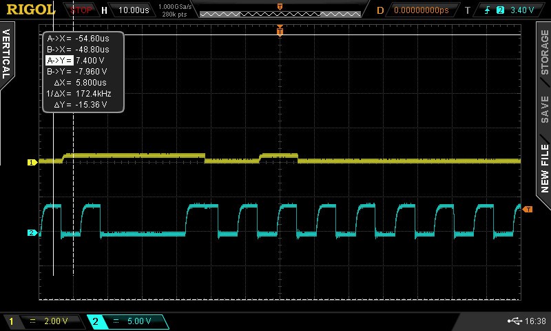
  • Yellow is SDA and Blue is SCL.

    SCL is running at around 170KHz. There is a clear Start bit and then either slave address or data, I'm unsure.

    In debug, the TXBUF is loaded with each character but that cant be seen on the SDA pin for some reason. And there is no STOP bit.


    Code I am running;

    #include <msp430f6776.h>
    
    unsigned char TXData = 0x01;
    unsigned char TXByteCtr = 5;
    
    void main(void)
    {
        WDTCTL = WDTPW | WDTHOLD;                         // Stop WDT
    
        __delay_cycles(1000000);
        // Setup P2.5 UCB0SCL, P2.6 UCB0SDA
        P2SEL0 |= BIT5 | BIT6;                             // Set P2.5,P2.6 to UCB0SCL, UCB0SDA
           
        // Setup eUSCI_B0
        UCB0CTLW0 |= UCSWRST;                             // Enable SW reset
        UCB0CTLW0 |= UCMST | UCMODE_3 | UCSSEL__SMCLK;    // I2C Master, use SMCLK
    
        UCB0BRW_L = 3;                                   // fSCL = SMCLK/12 = ~100kHz
        UCB0BRW_H = 0;
        UCB0I2CSA = 0xA0;                                 // Slave Address is 0A0h
        UCB0CTLW0 &= ~UCSWRST;                            // Clear SW reset, resume operation
        UCB0IE |= UCTXIE0;  
    
    
        while (1)
        {
            while (UCB0CTLW0 & UCTXSTP) ;                 // Ensure stop condition got sent
            UCB0CTLW0 |= UCTR | UCTXSTT;                  // I2C TX, start condition
    
            __bis_SR_register(GIE);                       // Enter LPM0 w/ interrupts
    
            TXData++;                                     // Increment data byte
        }
    }
    
    
    #pragma vector = USCI_B0_VECTOR
    __interrupt void USCI_B0_ISR(void)
    {  
        switch (__even_in_range(UCB0IV, 30))
        {
            case USCI_NONE: break;                        // No interrupts
            case USCI_I2C_UCALIFG: break;                 // ALIFG
            case USCI_I2C_UCNACKIFG: break;               // NACKIFG
            case USCI_I2C_UCSTTIFG: break;                // STTIFG
            case USCI_I2C_UCSTPIFG: break;                // STPIFG
            case USCI_I2C_UCRXIFG3: break;                // RXIFG3
            case USCI_I2C_UCTXIFG3: break;                // TXIFG3
            case USCI_I2C_UCRXIFG2: break;                // RXIFG2
            case USCI_I2C_UCTXIFG2: break;                // TXIFG2
            case USCI_I2C_UCRXIFG1: break;                // RXIFG1
            case USCI_I2C_UCTXIFG1: break;                // TXIFG1
            case USCI_I2C_UCRXIFG0: break;                // RXIFG0
            case USCI_I2C_UCTXIFG0:                       // TXIFG0
                if (TXByteCtr)                            // Check TX byte counter
                {
                    UCB0TXBUF = TXData;                   // Load TX buffer
                    TXByteCtr--;                          // Decrement TX byte counter
                }
                else
                {
                    UCB0IFG &= ~UCTXIFG;                  // Clear USCI_B0 TX int flag
                    UCB0CTL1 |= UCTXSTP;                  // I2C stop condition
                    //__bic_SR_register_on_exit(LPM0_bits); // Exit LPM0
                }
                break;
            case USCI_I2C_UCBCNTIFG: break;               // CNTIFG
            case USCI_I2C_UCCLTOIFG: break;               // LTOIFG
            case USCI_I2C_UCBIT9IFG: break;               // BIT9IFG
            default: break;
        }
    }

  • How exactly did you connect the EEPROM? Please describe the pullups in detail.
  • Both signal tracks are connect to DVCC (3.3V) via 10K pull ups.
     
     
              DVCC      DVCC
                  | |10K     | |10K             
    SDA----- |              |
    SCL-------------------

    These signals also go into the EEPROM.

    DVCC and GND pins are connected, WP is tied to GND and DVCC and GND have a cap between them.

  • SDA is clearly wrong. Are you sure the resistor is really 10K? Might there be some other component somewhere? Is this on a PCB, or a breadboard?
  • Checked the value, 10K and it is on a PCB. Are you confident in the firmware?

    I have just checked the pin outs and all is fine. It comes from pin 3 to the IC pin with a pull up 10K to DVCC.
  • The Master in in TX mode, does it have to be put into RX mode to receive the ACK or something?
  • The I²C module automatically handles TX/RX direction.

    The oscilloscope shows that there is something wrong with the SDA signal line; this is probably not a software problem.
  • So here is where I am at,

    Schematic that has been professionally made into a PCB..

    The waveform looks like the one above. Clock stretching perhaps? I didn't except the SCL to be having different periods.

    Code;

    void setup()
    {
    WDTCTL = WDTPW | WDTHOLD;                         // Stop WDT
    
        __delay_cycles(1000000);
        // Setup P2.5 UCB0SCL, P2.6 UCB0SDA
        P2SEL0 |= BIT5 | BIT6;                             // Set P2.5,P2.6 to UCB0SCL, UCB0SDA
           
        // Setup eUSCI_B0
        UCB0CTLW0 |= UCSWRST;                             // Enable SW reset
        UCB0CTLW0 = UCMST | UCMODE_3 | UCSSEL_2 | UCSYNC;    // I2C Master, use SMCLK
    
        UCB0BRW_L = 12;                                   // fSCL = SMCLK/12 = ~100kHz
        UCB0BRW_H = 0;
        UCB0I2CSA = 0xA0;                                 // Slave Address is 0A0h
        UCB0CTLW0 &= ~UCSWRST;                            // Clear SW reset, resume operation
        UCB0IE |= UCTXIE0;                                // Enable TX interrupt
    }
    
    void main()
    {
    unsigned char TXData = 0x01;
    unsigned char TXByteCtr = 0x05;
    setup();
    
    while (1)
        {
            while (UCB0CTLW0 & UCTXSTP) ;                 // Ensure stop condition got sent
            UCB0CTLW0 |= UCTR;                            // I2C TX, start condition
            UCB0CTL1 |= UCTXSTT;
            __bis_SR_register(GIE);                       // interrupts
    
            TXData++;                                     // Increment data byte
        }
    }
    
    
    #pragma vector = USCI_B0_VECTOR
    __interrupt void USCI_B0_ISR(void)
    {  
        switch (__even_in_range(UCB0IV, 30))
        {
            case USCI_NONE: break;                        // No interrupts
            case USCI_I2C_UCALIFG: break;                 // ALIFG
            case USCI_I2C_UCNACKIFG: break;               // NACKIFG
            case USCI_I2C_UCSTTIFG: break;                // STTIFG
            case USCI_I2C_UCSTPIFG: break;                // STPIFG
            case USCI_I2C_UCRXIFG3: break;                // RXIFG3
            case USCI_I2C_UCTXIFG3: break;                // TXIFG3
            case USCI_I2C_UCRXIFG2: break;                // RXIFG2
            case USCI_I2C_UCTXIFG2: break;                // TXIFG2
            case USCI_I2C_UCRXIFG1: break;                // RXIFG1
            case USCI_I2C_UCTXIFG1: break;                // TXIFG1
            case USCI_I2C_UCRXIFG0: break;                // RXIFG0
            case USCI_I2C_UCTXIFG0:                       // TXIFG0
                if (TXByteCtr)                            // Check TX byte counter
                {
                    UCB0TXBUF = TXData;                   // Load TX buffer
                    TXByteCtr--;                          // Decrement TX byte counter
                }
                else
                {
                    UCB0IFG &= ~UCTXIFG;                  // Clear USCI_B0 TX int flag
                    UCB0CTL1 |= UCTXSTP;                  // I2C stop condition
                    //__bic_SR_register_on_exit(LPM0_bits); // Exit LPM0
                }
                break;
            case USCI_I2C_UCBCNTIFG: break;               // CNTIFG
            case USCI_I2C_UCCLTOIFG: break;               // LTOIFG
            case USCI_I2C_UCBIT9IFG: break;               // BIT9IFG
            default: break;
        }
    }


  • I notice when I debug, when the Start bit is meant to go high, it doesn't. But also that UCBBUSY and UCSCLLOW go high indefinitely along with the UCNACKIFG.

  • To repeat myself: the voltage level on SDA is wrong. Something is pulling it low (to 0.4 V or so) even when it should be idle. The F6776 manages to pull it down to 0V when driving it, so this is probably a problem with another component (the EEPROM, or the pullup, or a short somewhere).
  • Perhaps the EEPROM is giving out a Low-level output?

    I can't see a short or anything like that.

  • Forget that, I was using a 10:1 probe by accident.

    So when it looks 0.33 it is actually 3.3V
  • Then it looks like a correct start of a transaction, but the slave address does not appear to be 0xA0. Could you capture a complete transaction?
  • That is all it does before repeating.
    I can't see in my code where I actually send the slave address, I just set it. Does the I2C automatically know to send it after I put it in Transmitter mode and sent the Start bit?

    Also I cant get the SMCLK (1MHz) to go above 170KHz, but that shouldn't affect the transmission at this point.
  • In the question, you said it just sits in no_operation(). How can it repeat?
    Is the code in the question the same code that you're executing right now?

    Did you check whether any of the other interrupt triggers happen?
  • Interrupts are working.

    No there is updated, very similar code that I posted earlier today.

    I have an updated waveform, that I think shows a start bit, slave address, an ACK and then some data and a stop bit. This then repeats indefinitely.

    Have a look and see what you think.

    Slave address is 0101000 and data is 0xFF but looks very faint and the STOP bit looks to only be very brief which sets alarms going.

  • It is working now, I wasn't waiting for the Start bit to end.

    I have another question, how do I write to specific memory locations? I can't see anything about it. Because then when I read back how do I know it is from the same location as I wrote to?

    Using a 2Kbit EEPROM.

    Cheers.

  • The datasheet of your EEPROM goes out of its way to avoid normal I²C terminology.

    But it works like most other I²C EEPROMs. The first byte of a write transaction is the address pointer. To read from a specific address, write the address, then generate a repeat-start condition, and read.
  • There is so little on actually writing to a specific address, its shocking.

    My problem is I want to write and then read back that value to see if communication is successful, however, once written the address pointer increments by 1 so isn't the same value anymore.

**Attention** This is a public forum