This thread has been locked.

If you have a related question, please click the "Ask a related question" button in the top right corner. The newly created question will be automatically linked to this question.

MSP432 2MBaud UART Operation - Missed characters

Other Parts Discussed in Thread: MSP430F5510

Hello all,


I am experimenting with sending data between two MSP_EXP432 Launchpads using EUSCI A0 as a 2MBaud UART and I'm finding that characters are being missed (Rx interrupt does not fire). 

EDIT: I specifically have trouble with SMCLK of 12MHz and a data rate of around 2MBaud.  Problem goes away if SMCLK is upped to 24MHz.

I am aware of this forum post but I don't think the issues there apply to my case - I am certain my ISR is fast enough for this job and I'm not seeing any UART error (overflows etc).   There are a few other factors that make me wonder if the MSP432 struggles to keep sync in particular configurations.

At this point I am working with an interrupt based implementation.  I know a DMA based implementation is better at these rates (indeed I can see that it would be very difficult to get any other work done while dealing with the interrupts), but my understanding is that DMA relies on the interrupt flags so I want to ensure that I understand that foundation before moving on.

[DMA UART Rx also raises a number of other questions - in particular, given that DMAs are of fixed size, how to implement in a way robust to missed/errored characters, but that is for another post].

Here is a CRO capture to illustrate my problem.

The top trace shows the runtime envelope for my EUSCI receive ISR.  It runs in just over 3uSec.  This is more than fast enough to keep up with 2MBaud (where one char is 5uSec).  This runtime can be further reduced with optimization but I choose not since it's not necessary at this point (and it gets in the way of debugging).

The middle trace is the Rx pin of the MSP432.  The signal here is nice and square with minimal overshoot etc.  I don't think a signal integrity problem is at play here.  You can see I'm transmitting a string of 0x00 here.  There number of missed characters seems to depend on the data.  0x00 is missed more often than something with more transitions like 0xAA.

The bottom trace shows that my scope is successfully able to decode the data - further evidence that the signal itself isn't too bad.

This next picture is just a close up just to prove the time in ISR is less than the character time.

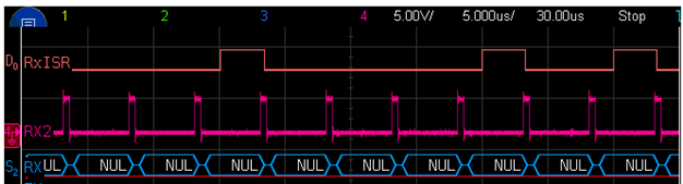
The problem here is in the top trace.  I've sent 32 chars, but the EUSCI interrupt has only fired 7 times (this is an extreme example - most bursts 32chars are received correctly.  Sometimes, one or two chars are missed.  Occasionally,  lots are missed).

There are no UART errors happening here (RxError, Overflow etc).  Character are just missed.

[That said, my college did some similar work and he always saw a missed character followed by an overflow error, so characters we always missed in pairs.  We can't work out why my result is different to his.  Code is very similar.  Maybe it is something to do with the MSP432 devices themselves??????]

Now, I've found that I only get missed characters with particular configurations.

Using a 12MHz SMCLK to drive the EUSCI module Baud rate setting between about 1.75MBaud to 2.05MBaud have lots of missed characters.  Outside this range the missed character rate falls away. 

If I set SMCLK to 24MHz, I never see any missed characters when operating around the 2MBaud mark.

I guess I have given a workaround to my own problem here.  

But (a) maybe this will help someone else in a similar situation in the future, (b) perhaps there is a real problem here that TI can take a look at???  and (b) this would have been difficult to debug if I had gone straight for DMA!

For reference, I attach a photo of my physical setup, and the code I used in trying to understand this issue.

//*****************************************************************************
// Test and understand high speed (2MBaud) UART operation
// Tested with two MSP-EXP432P401R Launchpads (XMS432 RevB silicon)
//
// Project created using the "Empty Project with DriverLib" template.
// Don't forget to put set ISR_EUSCI as the EUSCI_A0 ISR in system_msp432_p401r_ccs.c
// DEBUG build with optimization off
// Same code can go in both Launchpads provided hardware is setup correctly.  See below.
//
// At 2MBaud, I understand DMA is a better implementation approach!
// But DMA still relies on interrupts (interrupt flags).
// I want to understand interrupt operation and would appreciate if the
// following issues could be explained.
//
// ISSUE
//   Top level   - At 2MBaud, I find the MSP432 ocassionally fails to receive chars.
//   More detail - With 12MHz SMCLK, with baud rates around 2MBaud, the MSP432 occasionally fails
//                 to fire the EUSCI ISR for the EUSCI port in use.
//                 The number of failures seems to depend on the data being send with somthing like
//                 "0x00" (few transitions) giving more  missed ISRs than something like "0xAA"
//                 (lost of transitions)
//                 Specifically I find baud rates between 1.75MBaud and 2.05MBaud tend to
//                 miss their interrupts regularly.  Outside this range, errors are rare.
//                 I notice that if I set SMCLK to 24MHz, then the problem goes away.
//
//                 NOTE:  In the work I've done here, I've never seen a UART error (no RxError,
//                        Overflow etc).  The ISR doesn't fire, then the next char received
//                        is received without problem.
//                        However a collegue doing similar work as seen a pattern of missed
//                        ISR followed by an overflow error.
//
// ISSUE
//   I notice that the latest datasheed (SLA826D) ups the maximum fBITCLK value from 3MHz to 7MHz for VCORE1
//   Does that perhaps mean this issue might not occur in RevC silicon?
//
// ISSUE
//   Ref
//   It is not clear from the datasheet (SLA826B/D) if there is a relationship between feUSCI(MAX) and fBITCLK(MAX)
//   If I have VCORE=1 (1.4V) do I need to set SMCLK to 24MHz to be able to acheive the maximum fBITCLK?
//
// INTERCONNECTION
//
//     LaunchPadA (Rx)                          LaunchPadB (Tx)
// -------------------------                    -----------------------
//                          |                   |
//        (Rx - P1.2) JP4.3 |<------------------| JP4.4 (Tx - P1.3)   [DATA TRANSFER]
//                          |                   |
//                          |                   |
//             (P3.4) JP4.2 |<------------------| JP4.1 (P3.1)   [SYNC]
//                          |                   |
//                          |                   |
//                     P6.4 |--|                |
// Link pins to indicate RX |  |                |
//                     P5.5 |<-|                |
//                          |                   |
//  LED1 = UARTErr  [RED]   |                   |
//  LED2 = CountErr [GREEN] |                   |
//                     P3.6 |-> RxISR [DBG]     |
//                     P5.0 |-> UARTErr [DBG]   |
//                     P1.7 |-> CountErr [ DBG] |
//                          |                   |
// -------------------------                   -----------------------
//
// Every CYCLES_BEFORE_TX_STARTS "counts", the Tx end (LaunchPadB) does a "sync"
// (toggles P3.1 high for a bit), then bursts out NUM_CHARS_PER_BLOCK characters
// (contents of g_tx_data_u8_arr) on the UART Tx.
//
// - The Tx end is very simple and I don't care much about it's optimization
// - The Tx end appears to keep up at 2MBaud without problem.  My scope shows that
//   the Tx output is clean, and the scope is able to decode the Tx data without
//   problem.
// - Load on the processor could be reduced by using DMA.  I understand
//   DMA implementation for UART Tx.
//
// The Rx end polls its P3.4 (sync) and, if it detects a falling edge it
// resets it characters received count in preparation for the next burst.
// If a UART error occurs (overflow, Rx Err) the RED LED1 is flashed.
// If the number of characters received does does not match the expected, the GREEN LED2 is flashed.
//
// Debug pins.
//   P3.6   -  Frames the time the ISR is running to receive a character
//   P5.0   -  UART error flag occurred when receiving a character [=LED1]
//   P1.7   -  Did not receive expected number of chars during burst [=LED2 GREEN]
//
// Note: I use direct register operations rather than driverlib calls in the Rx ISR
//       because I find  that even with optimization very high, driverlib calls are
//       just too slow to keep up at 2MBaud
//****************************************************************************
#include <driverlib.h>
#include <stdio.h>
#include <string.h>
#include <stdbool.h>
#include <stdint.h>


// software-dl.ti.com/.../index.html

//----------------------------------------------------------------------------------------------
// SMCLK 24MHz - 2,100,000Baud - No error
//#define SMCLK_DIVIDER   CS_CLOCK_DIVIDER_2    // SMCLK = 24MHz
//#define CLKPRESCALER    11
//#define FIRSTMODREG     0
//#define SECONDMODREG    4
//#define OVERSAMPLING    EUSCI_A_UART_LOW_FREQUENCY_BAUDRATE_GENERATION
////#define OVERSAMPLING    EUSCI_A_UART_OVERSAMPLING_BAUDRATE_GENERATION

// SMCLK 24MHz - 2,000,000Baud - No error
//#define SMCLK_DIVIDER   CS_CLOCK_DIVIDER_2    // SMCLK = 24MHz
//#define CLKPRESCALER    12
//#define FIRSTMODREG     0
//#define SECONDMODREG    0
//#define OVERSAMPLING    EUSCI_A_UART_LOW_FREQUENCY_BAUDRATE_GENERATION
////#define OVERSAMPLING    EUSCI_A_UART_OVERSAMPLING_BAUDRATE_GENERATION

// SMCLK 24MHz - 1,800,000Baud - No error
//#define SMCLK_DIVIDER   CS_CLOCK_DIVIDER_2    // SMCLK = 24MHz
//#define CLKPRESCALER    13
//#define FIRSTMODREG     0
//#define SECONDMODREG    2
//#define OVERSAMPLING    EUSCI_A_UART_LOW_FREQUENCY_BAUDRATE_GENERATION
////#define OVERSAMPLING    EUSCI_A_UART_OVERSAMPLING_BAUDRATE_GENERATION


//----------------------------------------------------------------------------------------------
// SMCLK 12MHz - 2,050,000Baud - No errs
//#define SMCLK_DIVIDER   CS_CLOCK_DIVIDER_4    // SMCLK = 12MHz
//#define CLKPRESCALER    5
//#define FIRSTMODREG     0
//#define SECONDMODREG    7
//#define OVERSAMPLING    EUSCI_A_UART_LOW_FREQUENCY_BAUDRATE_GENERATION
////#define OVERSAMPLING    EUSCI_A_UART_OVERSAMPLING_BAUDRATE_GENERATION

// SMCLK 12MHz - 2,000,000Baud - Errs
#define SMCLK_DIVIDER   CS_CLOCK_DIVIDER_4    // SMCLK = 12MHz
#define CLKPRESCALER    6
#define FIRSTMODREG     0
#define SECONDMODREG    0
#define OVERSAMPLING    EUSCI_A_UART_LOW_FREQUENCY_BAUDRATE_GENERATION
//#define OVERSAMPLING    EUSCI_A_UART_OVERSAMPLING_BAUDRATE_GENERATION

// SMCLK 12MHz - 1,950,000Baud - Errs
//#define SMCLK_DIVIDER   CS_CLOCK_DIVIDER_4    // SMCLK = 12MHz
//#define CLKPRESCALER    6
//#define FIRSTMODREG     0
//#define SECONDMODREG    1
//#define OVERSAMPLING    EUSCI_A_UART_LOW_FREQUENCY_BAUDRATE_GENERATION
////#define OVERSAMPLING    EUSCI_A_UART_OVERSAMPLING_BAUDRATE_GENERATION

// SMCLK 12MHz - 1,900,000Baud - Errs
//#define SMCLK_DIVIDER   CS_CLOCK_DIVIDER_4    // SMCLK = 12MHz
//#define CLKPRESCALER    6
//#define FIRSTMODREG     0
//#define SECONDMODREG    2
//#define OVERSAMPLING    EUSCI_A_UART_LOW_FREQUENCY_BAUDRATE_GENERATION
////#define OVERSAMPLING    EUSCI_A_UART_OVERSAMPLING_BAUDRATE_GENERATION

// SMCLK 12MHz - 1,800,000Baud - Errs
//#define SMCLK_DIVIDER   CS_CLOCK_DIVIDER_4    // SMCLK = 12MHz
//#define CLKPRESCALER    6
//#define FIRSTMODREG     0
//#define SECONDMODREG    6
//#define OVERSAMPLING    EUSCI_A_UART_LOW_FREQUENCY_BAUDRATE_GENERATION
////#define OVERSAMPLING    EUSCI_A_UART_OVERSAMPLING_BAUDRATE_GENERATION

// SMCLK 12MHz - 1,750,000Baud - Errs
//#define SMCLK_DIVIDER   CS_CLOCK_DIVIDER_4    // SMCLK = 12MHz
//#define CLKPRESCALER    6
//#define FIRSTMODREG     0
//#define SECONDMODREG    7
//#define OVERSAMPLING    EUSCI_A_UART_LOW_FREQUENCY_BAUDRATE_GENERATION
////#define OVERSAMPLING    EUSCI_A_UART_OVERSAMPLING_BAUDRATE_GENERATION

// SMCLK 12MHz - 1,700,000Baud - No errs
//#define SMCLK_DIVIDER   CS_CLOCK_DIVIDER_4    // SMCLK = 12MHz
//#define CLKPRESCALER    7
//#define FIRSTMODREG     0
//#define SECONDMODREG    0
//#define OVERSAMPLING    EUSCI_A_UART_LOW_FREQUENCY_BAUDRATE_GENERATION
////#define OVERSAMPLING    EUSCI_A_UART_OVERSAMPLING_BAUDRATE_GENERATION


// If you move to a different port, adjust startup_msp432p401r_ccs.c accordingly
#define EUSCI_MODULE   EUSCI_A0_BASE

// All in the following group are set appropriately given EUSCI_MODULE
#define EUSCI_INT      INT_EUSCIA0
#define EUSCI_TX_PORT  GPIO_PORT_P1
#define EUSCI_TX_PIN   GPIO_PIN3
#define EUSCI_RX_PORT  GPIO_PORT_P1
#define EUSCI_RX_PIN   GPIO_PIN2


#define NUM_CHARS_PER_BLOCK     32     // Number of chars to transmit for each Tx block
#define CYCLES_BEFORE_TX_STARTS 100000   // Number of times through the main loop before the next Tx block begin.

#define CHAR_TO_SEND 0x00

// We use direct reg operations in ISR to speed things up compared to MSPWare calls.
#define EUSCI_REG EUSCI_A_CMSIS(EUSCI_MODULE)

#define P3_6_HIGH() P3->OUT |= BIT6
#define P5_0_HIGH() P5->OUT |= BIT0
#define P1_7_HIGH() P1->OUT |= BIT7
#define LED1_ON()   P1->OUT |= BIT0
#define LED2_RED_ON()   P2->OUT |= BIT0
#define LED2_GREEN_ON() P2->OUT |= BIT1
#define LED2_BLUE_ON()  P2->OUT |= BIT2

#define P3_6_LOW() P3->OUT &= ~BIT6
#define P5_0_LOW() P5->OUT &= ~BIT0
#define P1_7_LOW() P1->OUT &= ~BIT7
#define LED1_OFF() P1->OUT &= ~BIT0
#define LED2_RED_OFF()   P2->OUT &= ~BIT0
#define LED2_GREEN_OFF() P2->OUT &= ~BIT1
#define LED2_BLUE_OFF()  P2->OUT &= ~BIT2


volatile uint32_t g_time_count_u32 = 0;

const uint8_t g_err_mask_u8 = EUSCI_A_UART_FRAMING_ERROR + EUSCI_A_UART_OVERRUN_ERROR + EUSCI_A_UART_PARITY_ERROR + EUSCI_A_UART_BREAK_DETECT + EUSCI_A_UART_RECEIVE_ERROR;

//uint8_t g_tx_data_u8_arr[NUM_CHARS_PER_BLOCK] = "TestingTestingTestingTesting1234";
uint8_t g_tx_data_u8_arr[NUM_CHARS_PER_BLOCK] = {0};
volatile uint8_t  g_tx_ind_u8 = 0;
volatile uint8_t  g_rx_ind_u8 = 0;

volatile bool g_I_am_the_rx_board_b = false;

//--------------------------------------------------------------
//--------------------------------------------------------------
void ISR_EUSCI(void)
{

  uint8_t                   flags_u8;
  uint8_t                   rx_char_u8;

  if (g_I_am_the_rx_board_b)
  {
    P3_6_HIGH();

    // With direct register access, this ISR runs in about 3uSec with all optimization off.
    // I worry about turning on optimization - I do not want the RXBUF read below to be optimized
    // away!!!
    if (EUSCI_REG->IFG & EUSCI_A_UART_RECEIVE_INTERRUPT)
    {
      EUSCI_REG->IFG &= ~(EUSCI_A_UART_RECEIVE_INTERRUPT);  // Clear Rx interrupt flag
      flags_u8   = EUSCI_REG->STATW & g_err_mask_u8;
      rx_char_u8 = EUSCI_REG->RXBUF;

      if (flags_u8)
      {
        P5_0_HIGH();
        LED1_ON();
      }

      g_rx_ind_u8++;

      // datasheet says its possible to get an overrun as we are reading rx register, so read the flags again and clear if required
      // see 22.3.6 - Automatic Error Detection in eUSCI_A_Operation - Uart Mode
      flags_u8   = EUSCI_REG->STATW & g_err_mask_u8;
      if (flags_u8) {
        P5_0_HIGH();
        LED1_ON();
        rx_char_u8 = EUSCI_REG->RXBUF;
      }

      P5_0_LOW();
    }

    P3_6_LOW();
  }

  else

  {
    // Check for Tx interrupt
    if (MAP_UART_getEnabledInterruptStatus(EUSCI_MODULE) & EUSCI_A_UART_TRANSMIT_INTERRUPT)
    {
      // Don't need to clear the Tx flag!  That happens on MAP_UART_transmitData();
      if (g_tx_ind_u8 < NUM_CHARS_PER_BLOCK-1)
      {
        g_tx_ind_u8++;
        MAP_UART_transmitData(EUSCI_MODULE, g_tx_data_u8_arr[g_tx_ind_u8]);
      }
      else
      {
        // Done
        g_time_count_u32 = 0;
        MAP_UART_disableInterrupt(EUSCI_MODULE, EUSCI_A_UART_TRANSMIT_INTERRUPT);
      }
    }
  }
}


//--------------------------------------------------------------
//--------------------------------------------------------------
void main(void)
{
  eUSCI_UART_Config   uart_config_st;

  bool           current_rts_b = false;
  bool           last_rts_b = false;

  MAP_WDT_A_holdTimer();

  //--------------------------------------------------------------------
  // Platofrm specific setup

  // I_AM_RX_Sense
  MAP_GPIO_setAsInputPinWithPullDownResistor(GPIO_PORT_P6, GPIO_PIN4);

  // I_AM_RX_Set
  MAP_GPIO_setDriveStrengthLow(GPIO_PORT_P5, GPIO_PIN5);
  MAP_GPIO_setOutputHighOnPin(GPIO_PORT_P5, GPIO_PIN5);
  MAP_GPIO_setAsOutputPin(GPIO_PORT_P5, GPIO_PIN5);

  //TP1
  MAP_GPIO_setDriveStrengthLow(GPIO_PORT_P3, GPIO_PIN6);
  MAP_GPIO_setOutputLowOnPin(GPIO_PORT_P3, GPIO_PIN6);
  MAP_GPIO_setAsOutputPin(GPIO_PORT_P3, GPIO_PIN6);

  //TP2
  MAP_GPIO_setDriveStrengthLow(GPIO_PORT_P5, GPIO_PIN2);
  MAP_GPIO_setOutputLowOnPin(GPIO_PORT_P5, GPIO_PIN2);
  MAP_GPIO_setAsOutputPin(GPIO_PORT_P5, GPIO_PIN2);

  //TP3
  MAP_GPIO_setDriveStrengthLow(GPIO_PORT_P5, GPIO_PIN0);
  MAP_GPIO_setOutputLowOnPin(GPIO_PORT_P5, GPIO_PIN0);
  MAP_GPIO_setAsOutputPin(GPIO_PORT_P5, GPIO_PIN0);

  //TP4
  MAP_GPIO_setDriveStrengthLow(GPIO_PORT_P1, GPIO_PIN7);
  MAP_GPIO_setOutputLowOnPin(GPIO_PORT_P1, GPIO_PIN7);
  MAP_GPIO_setAsOutputPin(GPIO_PORT_P1, GPIO_PIN7);

  //LED1
  MAP_GPIO_setDriveStrengthLow(GPIO_PORT_P1, GPIO_PIN0);
  MAP_GPIO_setOutputLowOnPin(GPIO_PORT_P1, GPIO_PIN0);
  MAP_GPIO_setAsOutputPin(GPIO_PORT_P1, GPIO_PIN0);

  //LED2RED
  MAP_GPIO_setDriveStrengthLow(GPIO_PORT_P2, GPIO_PIN0);
  MAP_GPIO_setOutputLowOnPin(GPIO_PORT_P2, GPIO_PIN0);
  MAP_GPIO_setAsOutputPin(GPIO_PORT_P2, GPIO_PIN0);

  //LED2GREEN
  MAP_GPIO_setDriveStrengthLow(GPIO_PORT_P2, GPIO_PIN1);
  MAP_GPIO_setOutputLowOnPin(GPIO_PORT_P2, GPIO_PIN1);
  MAP_GPIO_setAsOutputPin(GPIO_PORT_P2, GPIO_PIN1);

  //LED2BLUE
  MAP_GPIO_setDriveStrengthLow(GPIO_PORT_P2, GPIO_PIN2);
  MAP_GPIO_setOutputLowOnPin(GPIO_PORT_P2, GPIO_PIN2);
  MAP_GPIO_setAsOutputPin(GPIO_PORT_P2, GPIO_PIN2);

  // RTS Output
  MAP_GPIO_setDriveStrengthLow(GPIO_PORT_P3, GPIO_PIN1);
  MAP_GPIO_setOutputLowOnPin(GPIO_PORT_P3, GPIO_PIN1);
  MAP_GPIO_setAsOutputPin(GPIO_PORT_P3, GPIO_PIN1);

  // CTS Input
  MAP_GPIO_setAsInputPin(GPIO_PORT_P3, GPIO_PIN4);


  //--------------------------------------------------------------------
  // Clock setup

  MAP_GPIO_setAsPeripheralModuleFunctionInputPin(GPIO_PORT_PJ, GPIO_PIN3, GPIO_PRIMARY_MODULE_FUNCTION);    // HFXIn
  MAP_GPIO_setAsPeripheralModuleFunctionOutputPin(GPIO_PORT_PJ, GPIO_PIN2, GPIO_PRIMARY_MODULE_FUNCTION);   // HFXOut

  MAP_GPIO_setAsPeripheralModuleFunctionInputPin(GPIO_PORT_PJ, GPIO_PIN0, GPIO_PRIMARY_MODULE_FUNCTION);    // LFXIn
  MAP_GPIO_setAsPeripheralModuleFunctionOutputPin(GPIO_PORT_PJ, GPIO_PIN1, GPIO_PRIMARY_MODULE_FUNCTION);   // LFXOut

  MAP_CS_setExternalClockSourceFrequency(32768, 48000000);

  // Start up the oscillators
  MAP_CS_startHFXT(false);
  MAP_CS_startLFXT(false);

  // Clock source settings
  MAP_CS_initClockSignal(CS_MCLK,   CS_HFXTCLK_SELECT, CS_CLOCK_DIVIDER_1);  // 48MHz
  MAP_CS_initClockSignal(CS_HSMCLK, CS_HFXTCLK_SELECT, CS_CLOCK_DIVIDER_2);  // 24MHz
  MAP_CS_initClockSignal(CS_SMCLK,  CS_HFXTCLK_SELECT, SMCLK_DIVIDER);
  MAP_CS_initClockSignal(CS_ACLK,   CS_REFOCLK_SELECT, CS_CLOCK_DIVIDER_1);  // 32768Hz
  MAP_CS_initClockSignal(CS_BCLK,   CS_REFOCLK_SELECT, CS_CLOCK_DIVIDER_1);  // 32768Hz - Divider setting is ignored for BCLK

  //--------------------------------------------------------------------
  // Power setup
  MAP_PCM_setPowerMode(PCM_DCDC_MODE);
  MAP_PCM_setCoreVoltageLevel(PCM_VCORE1);  // Vcore must be 1.4V to operate at over 1MBaud (up to 3MBaud)
  MAP_FlashCtl_setWaitState(FLASH_BANK0, 2);
  MAP_FlashCtl_setWaitState(FLASH_BANK1, 2);

  //--------------------------------------------------------------------
  // Data and direction setup
  g_I_am_the_rx_board_b = MAP_GPIO_getInputPinValue(GPIO_PORT_P6, GPIO_PIN4);
  memset(g_tx_data_u8_arr, CHAR_TO_SEND, NUM_CHARS_PER_BLOCK);

  //--------------------------------------------------------------------
  // UART Setup
  MAP_GPIO_setAsPeripheralModuleFunctionOutputPin(EUSCI_TX_PORT, EUSCI_TX_PIN, GPIO_PRIMARY_MODULE_FUNCTION);
  MAP_GPIO_setAsPeripheralModuleFunctionInputPin(EUSCI_RX_PORT, EUSCI_RX_PIN, GPIO_PRIMARY_MODULE_FUNCTION);

  uart_config_st.selectClockSource       = EUSCI_A_UART_CLOCKSOURCE_SMCLK,
  uart_config_st.clockPrescalar          = CLKPRESCALER,                       // =BRDIV
  uart_config_st.firstModReg             = FIRSTMODREG,                        // =UCxBFR
  uart_config_st.secondModReg            = SECONDMODREG,                       // =UCxBRS
  uart_config_st.parity                  = EUSCI_A_UART_NO_PARITY,
  uart_config_st.msborLsbFirst           = EUSCI_A_UART_LSB_FIRST,
  uart_config_st.numberofStopBits        = EUSCI_A_UART_ONE_STOP_BIT,
  uart_config_st.uartMode                = EUSCI_A_UART_MODE,
  uart_config_st.overSampling            = OVERSAMPLING,

  MAP_UART_initModule(EUSCI_MODULE, &uart_config_st);
  MAP_UART_enableModule(EUSCI_MODULE);

  // Ensure Tx reg is available
  while(!MAP_UART_getInterruptStatus(EUSCI_MODULE, EUSCI_A_UART_TRANSMIT_INTERRUPT)) {};

  // Enable interrupts
  MAP_Interrupt_setPriority(EUSCI_INT, (1 & 0x7) << 5);

  if (g_I_am_the_rx_board_b)
  {
    // Rx interrupt always runs on the Rx board, never on the Tx board
    MAP_UART_enableInterrupt(EUSCI_MODULE, EUSCI_A_UART_RECEIVE_INTERRUPT);
  }

  MAP_Interrupt_enableInterrupt(EUSCI_INT);

  if (g_I_am_the_rx_board_b)
  {
    printf("Starting - Rx module\n");
  }
  else
  {
    printf("Starting - Tx module\n");
  }


  //--------------------------------------------------------------------
  while(1)
  {
    g_time_count_u32++;

    if (g_I_am_the_rx_board_b)
    {
      // Rx board

      // Watch for falling edge of RTS to clear stats
      // All receive action happens in the ISR
      if (g_time_count_u32 % 10 == 0)
      {
        last_rts_b = current_rts_b;
        current_rts_b = MAP_GPIO_getInputPinValue(GPIO_PORT_P3, GPIO_PIN4);
        if (last_rts_b & !current_rts_b)
        {
          LED1_OFF();
          LED2_GREEN_OFF();

          // Last char count did not match the block size.
          if (g_rx_ind_u8 != NUM_CHARS_PER_BLOCK)
          {
            P1_7_HIGH();
            LED2_GREEN_ON();
          }

          // Now setup for the next block
          g_rx_ind_u8 = 0;
        }
        P1_7_LOW();
      }
    }
    else
    {
      // Tx board
      if (g_time_count_u32 == CYCLES_BEFORE_TX_STARTS)
      {
        MAP_GPIO_setOutputHighOnPin(GPIO_PORT_P3, GPIO_PIN1);
      }
      else if (g_time_count_u32 == CYCLES_BEFORE_TX_STARTS+50)
      {
        MAP_GPIO_setOutputLowOnPin(GPIO_PORT_P3, GPIO_PIN1);
      }
      else if (g_time_count_u32 == CYCLES_BEFORE_TX_STARTS+70)
      {
        // Kick off the transmission by sending first char.  ISR will take care of the rest
        g_tx_ind_u8 = 0;

        MAP_UART_clearInterruptFlag(EUSCI_MODULE, EUSCI_A_UART_TRANSMIT_INTERRUPT);
        MAP_UART_enableInterrupt(EUSCI_MODULE, EUSCI_A_UART_TRANSMIT_INTERRUPT);
        MAP_UART_transmitData(EUSCI_MODULE, g_tx_data_u8_arr[0]);
      }
    }
  }
}

  • If there are no other interrupts that "steal" time, you might have reached a hardware limit.

    I don't know the MSP432 in detail, but I would definitely test for other errors than overflow as well. Perhaps the signal is (or arrives) distorted beyond tolerance, and causes parity/noise errors. At least it does so on other Cortex-M MCUs.

       // I worry about turning on optimization - I do not want the RXBUF read below to be optimized
        // away!!!

    If RXBUF is properly defined (as "volatile"), there is no need to worry.

  • Check the status bits; if you have an overrun, you know that your code was too slow.

    At such a high data rate, it might be a better idea to use DMA.
  • G'Day Clemens,

    Thanks for your response.

    There is a status bit check in there and no Rx errors are ever detected.  (The only bit I see set in the UCAxSTATW reg is the UCBUSY bit.  This seems normal to me - if we are receiving a stream of data, the ISR will be processing the previous charact while the next character is arriving, so UCBUSY will be set during the ISR, except for the last char in the stream.  That is exactly what I see!).  

    I entirely agree the DMA is the only way to receive the data, and then do something useful with it at this data rate.

    But I have a situation where it would appear that, sometimes, the UCRXIFG flag is never set*.  In my understadning, DMA relies on the interrupt flags and if the interrupt flags aren't being set, a DMA implementation won't quite work (and it will be really hard to work out why!). 

    So until I understand this problem with the interrupts better, I worry about moving onto a DMA implementation.  Do you know of a complete working example of UART DMA at 2Baud?  Particularly one that can deal with occasional missed characters (a particular issue because DMA operations are setup with a fixed size in advance).

    * I assume UCRXIFG is not set because that is the only interrupt enabled for the module, and the corresponding module's ISR doesn't run.  

    Cheers

    Julian


  • G'Day f.m.

    Thank you for your response.

    The only interrupt going on here is the Rx interrupt so there is definately nothing else "stealing time".

    The code checks for all Rx error flags and none are every set.
    I'm reasonably sure there is no signal integrity problem here.
    I have the CRO connected as close as possible to the uC RX pin and I'm seeing nice clean signal.

    I can't see where driverlib makes RXBUF volatile - I'll look into that.
    Thanks!

  • Julian Kolodko said:

    I entirely agree the DMA is the only way to receive the data, and then do something useful with it at this data rate.

    I disagree on that, because there is no way to implement buffer handling with DMA. I was working on high BR with MSP430 UART, and missing characters problem in my case was related to slow ISR. It was dual USB - UART bridge based on MSP430F5510. At the end, with fastest possible ISR, it was able to go up to 4 Mbps on 24 MHz MCLK without any problems and lost characters.

  • On Cortex M devices, interrupts would tail-chain. Still, that would not necessarily prevent data loss, if too much time is spent in the ISR itself.

    My suggestion: Add GPIO pin toggling code to the ISR (H at entry, L at exit), and watch it on a scope, together with the serial line data. That could prove issues with the ISR duration.

  • there is no way to implement buffer handling with DMA

    Configure the DMA controller to raise an interrupt after every byte, or just use polling.

    In any case, DMA has the advantage that it runs even when an interrupt handler is currently executing. So even in the worst case, you have increased the buffer size from one byte (RXBUF) to multiple bytes.

  • In any case, DMA has the advantage that it runs even when an interrupt handler is currently executing. So even in the worst case, you have increased the buffer size from one byte (RXBUF) to multiple bytes.

    At least in theory.

    Actually, DMA must share the AHB with other masters. One needs to read the datasheet carefully for possible bus contentions. Unfortunately my knowledge of the MSP432 is rather limited, but I know this issue from other Cortex M devices. A FIFO doesn't need to share any bus until it is full - but it seems the MSP432 USCI/UART doesn't have one (in difference to the TM4C) ...

  • Clemens Ladisch said:

    Configure the DMA controller to raise an interrupt after every byte, or just use polling.

    In any case, DMA has the advantage that it runs even when an interrupt handler is currently executing. So even in the worst case, you have increased the buffer size from one byte (RXBUF) to multiple bytes.

    I spend significant time on this, and used DMA as starting point. DMA is made for data transfer with constant / fixed length between one location / peripheral to another. For transfer where receiver (in my case MSP430) don't know anything about data length (so it can be 3 bytes or 3 MBytes over UART at once, on high rate), I didn't found DMA as perfect solution for this. Also, DMA foreach transfer will stop (or slowdown) MSP430 CPU, and in some cases this is not acceptable behavior.

  • As a follow-up:

    The datasheet (slau356d.pdf, sect. 9.1, page 443) says, amongst others:

    "Performs all DMA transfers using the SINGLE AHB-Lite burst type."

    That means, all data are transferred at once, and DMA blocks all other AHB masters during the operation. Other vendor's implementations allow byte-, halfword- and word-sized single item transfer here. And from the description, it is not clear to me how the DMA controller behaves if the peripheral triggers the next item while a transfer is still in progress ...

    And further:

    "Destination data width is equal to the source data width."

    This would be byte-wise transfer in your case.

    All in all, sounds like you might run into core saturation problems either way.

  • Hi all,

    There was a fair bit of traffic overnight.  Thank you for your thoughts!  I'll repsond to each here:

     But first I just wanted to restate my original question (which was not clearly stated in the first place) :


    In implementing an interrupt based high speed (2MBaud) UART I am seeing:

    * Characters are missed if I run SMCLK = 12MHz, Bit rate = 2MBaud.    

    * Characters are never missed if I run SMCLK = 24MHz, Bit rate = 2MBaud (just adjust the prescaler in the UART configuration accordingly.)

    Why????


    Zrno:

    "I disagree on that, because there is no way to implement buffer handling with DMA"

    and

    "I spend significant time on this, and used DMA as starting point. DMA is made for data transfer with constant / fixed length between one location / peripheral to another. For transfer where receiver (in my case MSP430) don't know anything about data length (so it can be 3 bytes or 3 MBytes over UART at once, on high rate), I didn't found DMA as perfect solution for this."

    Yes, buffer handling is an interesting question.  I have a possible plan for that, but it’s a bit specific to my situation.

    In my application data is transferred over the UART in bursts.  I know in advance how many character to expect in a burst and at what intervals those bursts will occur.

    As such, I can clear out the receive buffer, start the DMA Rx to receive the expected number of chars, and start a timer that times out after the maximum possible receive period.  If the DMA Rx completion interrupt happens before the timer times out then all chars were received.  If the timer times out first, some characters were missed - need to deal with a corrupt "packet". 

    An alternative approach that would deal with unknown amounts of incoming data is to setup a timer and start a large DMA operation - larger than the number of chars I expect to receive before the timer fires.  Each time the timer fires, the running DMA is forced to halt (MAP_DMA_disableChannel()).  At this point, I think we can use the DMA control table to work out how many characters have been recieved (see DMA_ControlTable.dstEndAddr in dma.h) - and those characters can be copied out to another buffer for processing.  The timer and DMA operation can then be restarted.  Have to think carefully about how to avoid missing chars while the DMA operation is stopped.....   

    "At the end, with fastest possible ISR, it was able to go up to 4 Mbps on 24 MHz MCLK without any problems and lost characters."  

    Making the ISR fast enought to run as 4MBps on an MSP430 is quite an acheivement!  Even with the MSP432 running at 48MHz, I've been quite lean to get the ISR to run in time for 2MBps.

    [MSP432 RevB silicon seems to be limited to fBITCLK(max) = 3MBps anyway, but the RevC datasheet gives a 7MBps top speed].  

    In any case, for us, an interrupt based approach would never fly and is just a stepping stone on the way to DMA.  We have a lot of other stuff going on and we can't afford to spend any significant amount of time dealing with UART Rx interrupts.  


    f.m.:

    "Add GPIO pin toggling code to the ISR (H at entry, L at exit), and watch it on a scope, together with the serial line data."

    That is exactly what I did!  Refer to the RxISR trace in the oscilloscope traces above.  The ISR is most definitely running quickly enough to keep up with the data rate.  MOST of the time it will receive all 32chars in a burst just fine.  But, on some bursts, some characters are missed (the GPIO doesn't toggle indicating that the ISR didn't run for some reason).  Sometimes one or two character are missed, sometimes most characters are missed.


    Clemens:

    "Configure the DMA controller to raise an interrupt after every byte, or just use polling."

    I don't quite see the advantage of this over using the Rx interrupt directly.  In both cases you have to deal with an interrupt every 5uSec (at 2MBaud).


    Savings with the 1 character DMA approach:

    * Assuming you have mapped the DMA onto DMA_INT_1/2/3, you don't have to check/clear any interrupt flags.

    * You don't need to check the STATW register for UART errors (the DMA reading the RXBUF register wipes out the STATW register so there is nothing to read)

    * You don't need to copy the RXBUF register into your buffer, the DMA has done that already.


    Losses with the 1 character DMA approach:

    * Can't tell if a UART error has occurred.  

    * Still need to maintain your buffer pointers.

    * Need to do a MAP_DMA_setChannelTransfer() every 5uSec.  As a whole, this function is very heavy, but in my case I guess all I need to do is update the destination address.   

    * Then you need to reenable the DMA channel.  

    * Doesn't solve the problem of missed characters.


    Zrno:

    "Also, DMA foreach transfer will stop (or slowdown) MSP430 CPU, and in some cases this is not acceptable behavior."


    Hmm.... I'll have to understand this issue a bit more in the context of the MSP432.  To me, the point of DMA is to handle operations on your behalf without the processor getting involed.  But I guess any time the DMA has the bus, the processor needs to wait its turn????


    f.m.

    "That means, all data are transferred at once, and DMA blocks all other AHB masters during the operation."

    I'm not sure I'm following you here.  Are saying that even with DMA, there is a likelihood of missing characters?

    I agree with that.  What I've seen is interrupt missed when SMCLK=12MHz, 2MBaud.  But in addition to that, if you have multiple peripherals using DMA (on different DMA channels), then a lower priority DMA channel may end up missing data while the DMA engine is dealing with a higher priority channel.

    Regarding priority - there is an arbitration scheme.  When you configure DMA you tell the DMA engine how often to rearbitrate the bus (i.e. rearbitrate after 1/2/4/8/../1024 bytes).  If, at arbitration time a higher priority DMA channel needs the bus, the DMA engine switches to that channel.  Priority is based on a combination of channel number and a high/low priority setting for each channel. 

    With careful use this arbitration scheme could help reduce missed data I guess.


    Cheers

    Julian


  • I'm not sure I'm following you here.  Are saying that even with DMA, there is a likelihood of missing characters?

    For the UART alone, this would seem rather unlikely. 2Mbps would boil down to about 200kByte/s, corresponding one character every 5 us. Neither very critical itself for interrupts or DMA. Most AHB contention issues with DMA occuring with multiple channels from multiple sources (peripherals), which block each other.

    Beside a silicon issue,I would not rule out a signal issue. Your baudrate requires already "RF-safe" wiring (impedance matching), else the signal deformation (especialls rise/fall times) might cause character losses. The RS232 tolerances are relatively tight, AFAIK 2.5%. Does the MSP432 UART (eUSCI) have an option to set the oversampling factor ?

  • If device receiving data with fixed known length, where length is less then buffer size, and there is no interference between CPU and DMA, then DMA is best solution for sure.

    • Characters are missed if I run SMCLK = 12MHz, Bit rate = 2MBaud.    
    • Characters are never missed if I run SMCLK = 24MHz, Bit rate = 2MBaud

    The User's Guide says in sections 22.3.9.1 and 22.3.9.2:

    Modulation is based on the UCBRSx setting […]. A 1 in the table indicates that m = 1 and the corresponding BITCLK period is one BRCLK period longer than a BITCLK period with m = 0.
    Modulation for BITCLK16 is based on the UCBRFx setting […]. A 1 in the table indicates that the corresponding BITCLK16 period is one BRCLK period longer than the periods m = 0.

    So you should avoid modulation, especially if the ratio between the clock source and the bit rate is not very large (in that case, the relative timing error due to the longer/shorter bits is larger). If possible, use a clock that is an integer multiple of 8 times the bit rate.

  • I have oversampling disabled, no modulation (UCAxMCTLW reg = 0) and set set the prescaler (UCAxBRW) appropriately based on the SMCLK rate.

    With oversampling disabled, section 22.3.9.1 is relevant for me and it says

    "In this mode, the maximum eUSCI_A baud rate is one-third the UART source clock frequency BRCLK."

    For me, BRCLK = SMCLK = 12MHz, so 4MBaud is the theoretical limit (though the datasheet for the RevB parts gives a max of 3MBaud with VCORE1).  It would seem 2MBaud should be ok.

    I don't quite follow where your comment "If possible, use a clock that is an integer multiple of 8 times the bit rate" comes from, but I feel it is close to the core of this problem.  There is some other limit in the relationship between BRCLK and the "BITCLK" (Baudrate) that I'm hitting up against when I run SMCLK = 12MHz. 

    I think I'll continue on with SMCLK = 24MHz since that allows my clk to be at least 8 times the bit rate.  

  • Sorry, "integer multiple of 8 times" is wrong; what matters is the ratio between BRCLK and the bit clock.

    With 24 MHz, the possible errors are half as big as those with 12 Mhz, but they are still there.

    See section 22.3.12 for how to calculate the receive bit timing errors. (In this case, there are no transmit bit timing errors because there is no modulation.)
    See the USCI UART Calculator if you don't want to do the calculations by hand.

  • The output of that calculator is not immediately clear.

    --------------------------------------------------------------

    Low Frequency Baud Rate Generation

    Divider = 6; BRDIV = 6

    S-Modulation UCBRSx = 0

    UCxBR0UART = 6

    UCxBR1UART = 0

    UCxBRS = 0

    UCxBRF = 0

    Max. TX bit error: -1.3552527156068805e-13(-1.3552527156068805e-13, 0)

    Max. RX bit error (sync.: -0.5 BRCLK): -8.333333333333446(-8.333333333333446,0)

    Max. RX bit error (sync.: +/-0 BRCLK): -1.3552527156068805e-13(-1.3552527156068805e-13,0)

    Max. RX bit error (sync.: +0.5 BRCLK): 8.333333333333327(0,8.333333333333327)

    Max. RX bit error (over: -0.5,0,+0.5): 8.333333333333327(-8.333333333333446,8.333333333333327)

    ... not feasible!

    --------------------------------------------------------------

    I think it is telling me that for BRCLK = 12MHz, BitClk = 2MHz

    * Use Low frequency baud rate generation:

       * No Tx error.  

       * For Rx the three samples happen -8.33%, 0%, +8.33% from the middle of the bit period.  (reducing to 4.1% at BRCLK = 24MHz). 

    * I take the "...not feasible!" to mean that we can't do oversampling because BRCLK is not at least 16x BitClk.  (This message goes away if I make BRCLK >= 16x Baud rate)

    * All the other baud rate calculators I see online give 0% error for all bits with this configuration.

    This all seems fine to me...

    I'm wondering whether the eUSCI module stuggles to find the start bit in the 12Mhz/2MBaud configuration hence I see missed characters???

  • There are three possible error sources when receiving data:

    • Actions can happen only at the BRCLK edges. If BRCLK is not an integer multiple of the desired bit clock (if modulation is used), these actions happen at the wrong time.
      In your case, this error cannot happen.
    • The clocks of the transmitter and the receiver do not run at exactly the same speed.
      This error cannot be avoided, unless you synchronize the rate of the clocks of transmitter and receiver with a separate mechanism.
      However, when using a crystal (frequency error < 1%), this is usually not a problem.
    • The transmitter can switch the voltage at any random time, but the receiver samples the signal only with BRCLK. So there is random jitter of up to one BRCLK tick in the detected time of the start bit.
      This error cannot be avoided, unless you synchronize the rate and the phase of the clocks of transmitter and receiver with a separate mechanism.

    All the other baud rate calculators compute only the first error. The calculator on the TI wiki computes the first and the third.


    As a rule of thumb, you should try to keep the errors as small as possible (< 1%). So if you can use 24 MHz, do it.

  • Thank you Clemens

**Attention** This is a public forum