This thread has been locked.

If you have a related question, please click the "Ask a related question" button in the top right corner. The newly created question will be automatically linked to this question.

4- wire Jtag with MSP432

Other Parts Discussed in Thread: MSP-TS432PZ100

Hello Team,

I have a customer who is looking at our MSP432 for their next design. They have questions on the 4- wire JTAG interfacing for this device. The specific question was when using 4 wire JTAG, do we need external resistors on TMS, TCK, TDO and if so, what values ?

I referred the thread https://e2e.ti.com/support/microcontrollers/msp430/f/166/t/34282 I was not sure whether the same applies to the MSP432? 

Also on page 58 of the datasheet http://www.ti.com/lit/ds/symlink/msp432p401m.pdf there are typical values for pull ups and pull downs. Do they apply in this case.

Thank you for your assistance.

  • Hello Kishen,

    No, you do not require external resistors on the TMS/TCK/TDO/TDI pins.

    Regards,
    Ryan
  • Ryan as per table 4-4 on page 27 of the data sheet ( www.ti.com/.../slas826e.pdf ) that was updated in July 2016:
    regarding pin PJ.5/TDO/SWO: "When used as JTAG TDO/SWO pin, it should be pulled down externally."

    The table goes on to suggest pullup and pulldown for TMS and TCK. TDI is suggested to be left open.
    I have a couple of questions:

    1) Please clarify why the table suggests these pull ups and pull downs. I am using these pins for JTAG and connecting them to a XDS100 V2 JTAG cable.
    2) What values of pull up and pull down resistors should be used ?
    3) I have been having problems with programming the MSP432 using JTAG. I ran the JTAG connectivity test and the the test results shows "The JTAG IR Integrity scan-test has failed." & "The JTAG DR Integrity scan-test has failed".
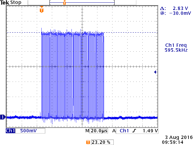
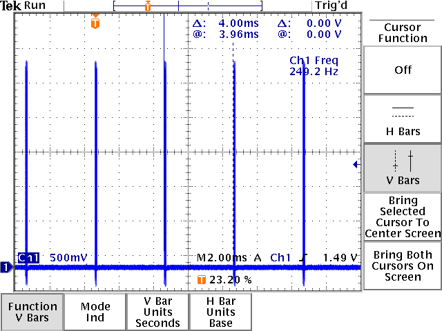
    4) When I probe the TDO pin on the MSP432, without connecting the JTAG cable I see that a 600KHz burst of clocks is generated for 20-30 cycles and this repeats every 4mS. This is an un-programmed MSP432 IC, so no code has been written to generate the 600KHz clock burst.

    The JTAG integrity test failures made me look at the data sheet where I found the suggestions to use pull-ups and pull-downs for the JTAG port.
    Besides the check of the jtag wires is there any other things you can suggest I try to resolve the JTAG programming issue? Thanks
  • Have you referred to the MSP432 Hardware Tools User's Guide (SLAU571)? www.ti.com.cn/.../slau571a.pdf

    Please double-check that you are using all of the correct connections.

    Regards,
    Ryan
  • Thank you for you reply Ryan,

    Yes, I cross checked the connections as per the document you referred to.

    The JTAG pins do not seem to have any significant reflections so its hard for me to explain this as a signal integrity issue.

    I even tried adding the pull-ups and pull-downs (10K) on the JTAG TDO , TMS, TCK and (47K on the) NRST pins as mentioned in the datasheet.

    I also did the MSP432 factory reset just in case the device is in an unknown state (I ran the factory reset script using the target configuration DAP)

    I am still unable to get a pass on the JTAG connection test. I have included the results below.

    I have also attached two images of the TDO pin output on a scope. I probed the MSP432 after a power on reset.

    2 different time scales are shown separately.

    As I had mentioned previously the MSP is toggling a 600KHz clock on the TDO for some cycles every 4mS. This happens even if the XDS100 JTAG cable is removed.

    Is this normal? Does the 600KHz clock suggest that the JTAG port on this chip is not functioning as expected, post-power on reset ?

    The MSP432 is on a custom PCB. I am using a XDS100 V2 JTAG with a custom interface board to interface the custom PCB to the XDS100 14-pin JTAG connector.

    Earlier, We were able to program the MSP correctly. But after some time we were not able to communicate with the board.

    Please let me know if you have any thoughts on how to resolve this. Thank you.

    ===============================================================

    [Start: Texas Instruments XDS100v2 USB Debug Probe_0]

    Execute the command:

    %ccs_base%/common/uscif/dbgjtag -f %boarddatafile% -rv -o -F inform,logfile=yes -S pathlength -S integrity

    [Result]


    -----[Print the board config pathname(s)]------------------------------------

    C:\Users\harshits\AppData\Local\TEXASI~1\
    CCS\ti\0\0\BrdDat\testBoard.dat

    -----[Print the reset-command software log-file]-----------------------------

    This utility has selected a 100- or 510-class product.
    This utility will load the adapter 'jioserdesusb.dll'.
    The library build date was 'Apr 27 2016'.
    The library build time was '23:27:56'.
    The library package version is '6.0.228.0'.
    The library component version is '35.35.0.0'.
    The controller does not use a programmable FPGA.
    The controller has a version number of '4' (0x00000004).
    The controller has an insertion length of '0' (0x00000000).
    This utility will attempt to reset the controller.
    This utility has successfully reset the controller.

    -----[Print the reset-command hardware log-file]-----------------------------

    The scan-path will be reset by toggling the JTAG TRST signal.
    The controller is the FTDI FT2232 with USB interface.
    The link from controller to target is direct (without cable).
    The software is configured for FTDI FT2232 features.
    The controller cannot monitor the value on the EMU[0] pin.
    The controller cannot monitor the value on the EMU[1] pin.
    The controller cannot control the timing on output pins.
    The controller cannot control the timing on input pins.
    The scan-path link-delay has been set to exactly '0' (0x0000).

    -----[The log-file for the JTAG TCLK output generated from the PLL]----------

    There is no hardware for programming the JTAG TCLK frequency.

    -----[Measure the source and frequency of the final JTAG TCLKR input]--------

    There is no hardware for measuring the JTAG TCLK frequency.

    -----[Perform the standard path-length test on the JTAG IR and DR]-----------

    This path-length test uses blocks of 64 32-bit words.

    The test for the JTAG IR instruction path-length failed.
    The many-ones then many-zeros tested length was -1313 bits.
    The many-zeros then many-ones tested length was -1697 bits.

    The test for the JTAG DR bypass path-length failed.
    The many-ones then many-zeros tested length was -97 bits.
    The many-zeros then many-ones tested length was -416 bits.

    -----[Perform the Integrity scan-test on the JTAG IR]------------------------

    This test will use blocks of 64 32-bit words.
    This test will be applied just once.

    Do a test using 0xFFFFFFFF.
    Test 1 Word 0: scanned out 0xFFFFFFFF and scanned in 0xFFFFFFF1.
    Test 1 Word 38: scanned out 0xFFFFFFFF and scanned in 0x94AFFFFF.
    Test 1 Word 39: scanned out 0xFFFFFFFF and scanned in 0xAD6B5A52.
    Test 1 Word 40: scanned out 0xFFFFFFFF and scanned in 0x4A52D6B5.
    Test 1 Word 41: scanned out 0xFFFFFFFF and scanned in 0xFFFFFE29.
    Scan tests: 1, skipped: 0, failed: 1
    Do a test using 0x00000000.
    Test 2 Word 0: scanned out 0x00000000 and scanned in 0x0000000F.
    Scan tests: 2, skipped: 0, failed: 2
    Do a test using 0xFE03E0E2.
    Test 3 Word 0: scanned out 0xFE03E0E2 and scanned in 0xE03E0E20.
    Test 3 Word 1: scanned out 0xFE03E0E2 and scanned in 0xE03E0E2F.
    The details of the first 8 errors have been provided.
    The utility will now report only the count of failed tests.
    Scan tests: 3, skipped: 0, failed: 3
    Do a test using 0x01FC1F1D.
    Scan tests: 4, skipped: 0, failed: 4
    Do a test using 0x5533CCAA.
    Scan tests: 5, skipped: 0, failed: 5
    Do a test using 0xAACC3355.
    Scan tests: 6, skipped: 0, failed: 6
    Some of the values were corrupted - 68.2 percent.

    The JTAG IR Integrity scan-test has failed.

    -----[Perform the Integrity scan-test on the JTAG DR]------------------------

    This test will use blocks of 64 32-bit words.
    This test will be applied just once.

    Do a test using 0xFFFFFFFF.
    Test 1 Word 0: scanned out 0xFFFFFFFF and scanned in 0xFFFFFFFE.
    Test 1 Word 58: scanned out 0xFFFFFFFF and scanned in 0x6B5ACFFF.
    Test 1 Word 59: scanned out 0xFFFFFFFF and scanned in 0x5294A529.
    Test 1 Word 60: scanned out 0xFFFFFFFF and scanned in 0xB5AD6B4A.
    Test 1 Word 61: scanned out 0xFFFFFFFF and scanned in 0xFFFFFFFE.
    Scan tests: 1, skipped: 0, failed: 1
    Do a test using 0x00000000.
    Test 2 Word 0: scanned out 0x00000000 and scanned in 0x00000001.
    Scan tests: 2, skipped: 0, failed: 2
    Do a test using 0xFE03E0E2.
    Test 3 Word 0: scanned out 0xFE03E0E2 and scanned in 0xFC07C1C4.
    Test 3 Word 1: scanned out 0xFE03E0E2 and scanned in 0xFC07C1C5.
    The details of the first 8 errors have been provided.
    The utility will now report only the count of failed tests.
    Scan tests: 3, skipped: 0, failed: 3
    Do a test using 0x01FC1F1D.
    Scan tests: 4, skipped: 0, failed: 4
    Do a test using 0x5533CCAA.
    Scan tests: 5, skipped: 0, failed: 5
    Do a test using 0xAACC3355.
    Scan tests: 6, skipped: 0, failed: 6
    Some of the values were corrupted - 68.2 percent.

    The JTAG DR Integrity scan-test has failed.

    [End: Texas Instruments XDS100v2 USB Debug Probe_0]

  • Since the MSP432 was once in a working condition then I would have to assume that it was damaged at some point during testing. Was the board ever subjected to high voltages or ESD? Were any noticeable changes made between the working and damaged conditions? Would it be possible to replace the MSP432 on this board to see if a new MCU works, or likewise move the MSP432 to a different custom board?

    I will try to bring someone into this thread who knows more about the MSP432 JTAG. Would it be possible for you to provide your custom board schematic and layout image?

    Edit: I have some further Wikis for you to reference before we bring in further experts:

    http://processors.wiki.ti.com/index.php/XDS_Connector_Design_Checklist

    http://processors.wiki.ti.com/index.php/XDS_Target_Connection_Guide

    http://processors.wiki.ti.com/index.php/Debugging_JTAG_Connectivity_Problems

    Regards,
    Ryan

  • Hello Ryan,

    Replacing the MSP432 did not change anything. The JTAG connectivity test failed just like before and the TDO pin kept showing the 600KHz-burst of clocks every 4 milliseconds.

    Also I have cross checked the connections with respect to all the checklists including a schematic from TI for an evaluation board : MSP-TS432PZ100_sch.pdf.

    I still think that the 600KHz clock on the TDO pin post power on reset, is a clue for the root cause (I had shown 2 figures in my previous post). 

    FYI when I manually assert the nRST/NMI pin of the MSP432 by touching a ground probe to the nRST net , the 600KHz clock goes away so the MSP is only generating the 600KHz clock after reset is de-asserted.

    We have built multiple custom boards and they are all working fine, except this board which was working fine and then stopped working (unable to program the MSP432). All sanity checks are fine : clean power supply DVCC, AVCC, Vcore. Current draw is very low : no board short circuits. The same XDS100V2 adapter with the same custom adapter board that interfaces to the custom boards JTAG pins is able to program other boards just fine.

    Is there any reason why a new - un-programmed - MSP432 would start driving its TDO pin with a 600KHz-burst of clocks every 4milliseconds ? 

    Thank you

  • Can you try using SWD and see if communication/programming works through this method?

    I cannot explain why you are seeing the 600 kHz bursts, this is indeed odd behavior. But the fact that other MSP432 devices also do not work on this board and knowing that your other custom boards operate properly leads me to believe that the issue lies with the board as compared to the MSP432 itself, although your sanity checks are thorough. Do MSP432 devices removed from this faulty board work with other target/custom boards? Are you using Rev B or C MSP432 devices?

    Regards,
    Ryan
  • Hi Ryan,

    -We are using an XDS100V2 JTAG programming emulator: which, correct me if I am wrong, does not support SWD.

    -I agree : something on this specific PCB caused the MSP432 to enter this unknown state. To debug this, I removed all the components except for the essential ones required for MSP432 operation. We also removed the regulators and directly powered the MSP from a DC power supply. The JTAG programming issue still persists and the 600KHz clock still shows up. We then X-rayed the PCB to see if there were any obvious faults in the PCB and could not find anything obvious.

    -We are using the XMS432 Rev B. Devices and I am aware of the newly released Rev. C devices. However I would prefer staying with the Rev B for now.

    -Is there any possibility of you asking some experts who know about the JTAG and the BSL. If someone can tell me what could possibly cause an un-programmed MSP432 to output the 600KHz clock on the TDO pin, then I can try to work backwards and see what fault in the PCB caused this erroneous state to occur.

    Again, thanks for you help.

**Attention** This is a public forum