This thread has been locked.

If you have a related question, please click the "Ask a related question" button in the top right corner. The newly created question will be automatically linked to this question.

How to monitor battery voltage for MSP430F5528?

Other Parts Discussed in Thread: MSP430F5528, MSP430FR6972

Hi,

I am using a custom made board having MSP430F5528  and powering it up with  a battery using solar panel, i want to write a code for monitoring  the voltage level of the battery so do i need to use ADC for that? How should i proceed further?

Thank You,

Pratiksha Bhuta

  • If you need high resolution then ADC is the best way. Read the user guide. It is very easy to configure ADC.

  • Hi!

    You should download the code examples and look at:

    MSP430F55xx_adc_01.c              ADC12, Sample A0, Set P1.0 if A0 > 0.5*AVcc
    MSP430F55xx_adc_02.c              ADC12, Using the Internal Reference
    MSP430F55xx_adc_05.c              ADC12, Using an External Reference
    MSP430F55xx_adc_06.c              ADC12, Repeated Sequence of Conversions
    MSP430F55xx_adc_07.c              ADC12, Repeated Single Channel Conversions
    MSP430F55xx_adc_08.c              ADC12, Using A8 and A9 Ext Channels for Conversion
    MSP430F55xx_adc_09.c              ADC12, Sequence of Conversions (non-repeated)
    MSP430F55xx_adc_10.c              ADC12, Sample A10 Temp and Convert to oC and oF

    These are various examples on how to use the ADC12 module.

    Dennis

  • Hi Pratiksha,

    another approach might be to use the internal Supply Voltage Monitor (SVM) Module.
    If you are not interested in the exact battery voltage, but just want to react if the voltage drops below a configured voltage setting, this might be the better choice.

    Thanks and best regards,
    Christoph

  • Hi  Christoph Dohrn,

    Can you guide me on how to configure the Internal Supply Voltage Monitor (SVM) Module?                                                                    

    Thank You,

    Regards

    Pratiksha Bhuta

  • Hi Pratiksha!

    The User's Guide explains the usage of the PMM module and the SVS in chapter 2, starting from page 98. Read this first to get an idea of the functionality and the configuration. What is your target monitor threshold and what shall happen if undershot?

    Dennis

  • Hi Pratiksha,

    Dennis is right. It is a good idea to read the User's Guide chapter on SVS/SVM, especially since there are some dependencies with regards to the allowed combinations of SVS, SVM and Vcore setting.

    The Low Side SVM/SVS are checking the internal Vcore. The High Side SVM/SVS are checking the external Vcc.
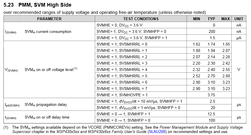
    The basic idea behind the SVM is that you get an interrupt at a Vcc level you can configure as pre warning that your berrety is low. The SVS will reset your device because Vcc has reached a level below the minimum requirement of your application.

    You can find the corresponding voltages to each setting in the datasheet:

    Thanks and best regards,
    Christoph

  • Another approach to monitor battery voltage is the comparator module. I have a blog talking about this approach. Please check www.rcfocus.tw.
  • HI Robert Chen,

    As suggested by your blog i configured the comparator_B of MSP430F5528 but there is not output in the registers, it states Error: unable to read,
    so how are where do i check the voltage and the output of the comparator?

    Below is the code :

    #include <msp430.h>
    #include "msp430f5528.h"
    #include "math.h"

    /*
    * main.c
    */
    int main(void)
    {
    WDTCTL = WDTPW | WDTHOLD; // Stop watchdog timer
    P6DIR |= BIT0; //selecting CB0 as the V- terminal(3.3V input to be compared with refrence)
    P6OUT |= BIT0;
    REFCTL0 |= REFOUT; // Enable REFOUT
    CBCTL0 = CBIPSEL_0|CBIPEN; // CB0 is set to V+ terminal
    CBCTL1 = CBPWRMD_1|CBFDLY_2|CBF;
    CBCTL2 = CBRS_0|CBREFL_2|CBRSEL; // selecting refrence of 2volts and applying at V- terminal

    int checkVoltage();
    {
    CBCTL1 |= CBON; // Enable COMPE_B
    __delay_cycles(1000); // Wait for filter circuit to be stable
    int cbout = CBCTL1 & CBOUT; // Get result
    CBCTL1 &= ~CBON; // Disable COMP_B
    return cbout;
    }


    }
  • The output of COMP_B is a bit only i.e. the CBOUT bit. "1" means the voltage on V+ is greater than V-. Which code (line) produces the error "unable to read"?

    Unlike MSP430FR6972, the reference output of MSP430F5528IRGC is pin-9 (VREF+) and the CB0 input is pin-1. So you have to manually short (connect) these two pins in your PCB board. For FR6972, they are the same pin, so they are already shorted.

    The idea is, the REFOUT at pin 9 is routed to input at CB0 as V- terminal. So, you have to check the mounted IC package and ensure the two pins are connected.

    Below is the code I used in a MSP430F5430 project to detect the rough battery voltage. I use C++ for this project. The variable status and voltage are member variables. prcm is another C++ class. prcm.delay_us() is just like __delay_cycles() but delays in micro-seconds.

    This example is exact what you need. You only have to adjust the pinout.

    void BatMon::update()
    {
    	// Battery curve:
    	//	0% 		5%		10%		20%		100%
    	//	2.0V	2.7V	2.85V	2.89V	2.95V
    
        // The idea is to output VREF+ at P5.0 which is connected with P6.5 as CB5 input of comparator.
        // Compare VCC (through resistor ladder) with VREF(1.5V).
    	//	V*(i+1)/32 > 1.5
    	//	V*(i+1) > 48
    	//	V > 48/(i+1)
    	//
    	//	48/(15+1) = 3.000
    	//	48/(16+1) = 2.823
    	//	48/(17+1) = 2.667
    	//	48/(18+1) = 2.526
    
        // Enable COMP_B
    	REFCTL0 |= REFOUT|REFON;				// Enable REFOUT
        CBCTL0 = CBIMSEL_5|CBIMEN;				// CB5 is set to V- terminal
        CBCTL1 = CBPWRMD_1|CBFDLY_2;
        CBCTL3 |= (1<<5);						// Select CB5 function at P6.5
    	CBCTL1 |= CBON;							// Enable COMPE_B
    
        int i = 15;
    	for (; i<18; i++) {
    		CBCTL2 = CBRS_1|(i<<8)|(i<<0);		// CBREF(VCC) is set to V+ terminal
    		prcm.delay_us(1);					// Wait for filter circuit to be stable
    		if (CBCTL1 & CBOUT)
    			break;
    	}
    
    	// Disable COMP_B
    	CBCTL1 &= ~CBON;						// Disable COMP_B
    	REFCTL0 &= ~REFOUT;						// Don't clear REFON since ADC may be using it
    
    	int mV;
    	switch (i-15) {
    		case 0:
    			status = BAT_NEW;
    			mV = 3000;
    			break;
    		case 1:
    			status = BAT_GOOD;
    			mV = 2823;
    			break;
    		case 2:
    			status = BAT_OK;
    			mV = 2667;
    			break;
    		case 3:
    			status = BAT_LOW;
    			mV = 2526;
    			break;
    		default:
    			status = BAT_CRITICAL;
    			mV = 2400;
    			break;
    	}
    
    	voltage = (status<<12) | mV;
    }

  • Hi,
    I studied the comparator module again as tried o code the following as per my understanding, I have applied Input Voltage to CBO (V+ terminal of comparator ) and configured an internal reference voltage of 2.5 v (V- terminal of comparator ) but the CBOUT is always 1 even if V+ is less than V-
    for which i am glowing the LED.
    so what could be the error in the code below please help
    #include <msp430.h>
    #include <msp430f5528.h>
    #include <math.h>

    int main (void)
    {
    float Batt;
    REFCTL0 |= REFOUT|REFON; //Turn ON the reference module to enable 2.5V reference
    WDTCTL = WDTPW + WDTHOLD; ///Stop the watch dog timer
    CBCTL0 = CBIPEN + CBIPSEL_0; /// enable CB0 as +V terminal of comparator
    CBCTL1 = CBPWRMD_1 + CBFDLY_1 + CBF; /// normal power mode, filter delay to 900ns, output to be filtered
    CBCTL2 = CBREFL_3 + CBRSEL + CBRS_1; /// reference of 2.5V, select V- terminal were 2V is applied
    CBCTL1 = CBON; /// Turn ON the comparator

    while(1)
    {
    Batt = CBCTL1 & CBOUT;
    if (Batt == 0x0001)
    {
    P4DIR |= BIT7; /// glow led
    P4OUT = BIT7;

    }
    else
    {

    }

    }

    }
  • Obviously there are some errors in your program.

    (1) Please look at the default value of REFCTL0, REFMSTR=1 and REFVSEL=0. So, REFOUT is controlled by ADC module and REF voltage = 1.5V. You have to set REFCTL0 = REFVSEL_2|REFOUT|REFON. Don't use "|=".

    (2) Don't use "float Batt" and compare it with bits. You should use "int Batt" to compare it with 0x0001.

    I don't check CBCTLx settings yet. But you should fix the above two issues and try again.
  • HI Robert Chen

    i did the following changes but still when i reduce the battery voltage below 2.5V CBOUT remains 1 no change in CBOUT , are my CBTLx settings proper???
    #include <msp430.h>
    #include <msp430f5528.h>
    #include <math.h>

    int main (void)
    {
    int Batt;

    WDTCTL = WDTPW + WDTHOLD; ///Stop the watch dog timer
    REFCTL0 = REFVSEL_2|REFOUT|REFON; //Turn ON the reference module to enable 2.5V reference
    CBCTL0 = CBIPEN + CBIPSEL_0; /// enable CB0 as +V terminal of comparator
    CBCTL1 = CBPWRMD_1 + CBFDLY_1 + CBF; /// normal power mode, filter delay to 900ns, output to be filtered
    CBCTL2 = CBREFL_3 + CBRSEL + CBRS_1; /// reference of 2.5V, select V- terminal were 2V is applied
    CBCTL1 = CBON; /// Turn ON the comparator

    while(1)
    {
    Batt = CBCTL1 & CBOUT;
    if (Batt == 0x0001)
    {
    P4DIR |= BIT7; ///glow led if CBOUT=1
    P4OUT = BIT7;

    }
    else
    {

    }

    }

    }
  • "CBCTL1 = CBON" should use "|=", right?

**Attention** This is a public forum