This thread has been locked.

If you have a related question, please click the "Ask a related question" button in the top right corner. The newly created question will be automatically linked to this question.

MSP430 and I2C frequency

Other Parts Discussed in Thread: MSP430F6779A, MSP430F67791A, MSP-TS430PEU128

Hello,


I have an MSP430F6779A with an I2C bus activated (to drive a little oled screen).

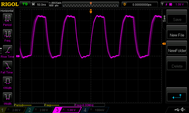
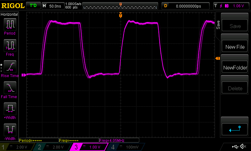
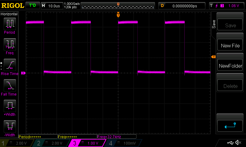
My clocks are : MCLK = 8 MHz, SMCLK = 4 MHz and ACLK (from XT1) = 32,768 kHz.

// Set the correct VCore.
core_setVcoreUp(PMMCOREV_0);
core_setVcoreUp(PMMCOREV_1);
core_setVcoreUp(PMMCOREV_2);

// Configure XT1.
UCSCTL6	&= ~(XT1OFF);
UCSCTL6 |=  XCAP_3;
do
{
    UCSCTL7 &= ~(XT1LFOFFG);
} while (UCSCTL7 & XT1LFOFFG);   

// Configure DCO.
UCSCTL3 |= SELREF__XT1CLK;
__bis_SR_register(SCG0);
UCSCTL0 = 0x0000;
UCSCTL1 = DCORSEL_5;
UCSCTL2 = FLLD_1 | 245;
__bic_SR_register(SCG0);

// Init clocks : MCLK = SMCLK = 8 MHz, ACLK = 32768 Hz.
UCSCTL4 = SELA__XT1CLK | SELS__DCOCLKDIV | SELM__DCOCLKDIV;

// Divide SMCLK by 2 > 4 MHz. UCSCTL5 |= DIVS__2; __delay_cycles(250000); do { UCSCTL7 &= ~(XT1LFOFFG | DCOFFG); SFRIFG1 &= ~OFIFG; } UCSCTL6 &= ~(XT1DRIVE_3);

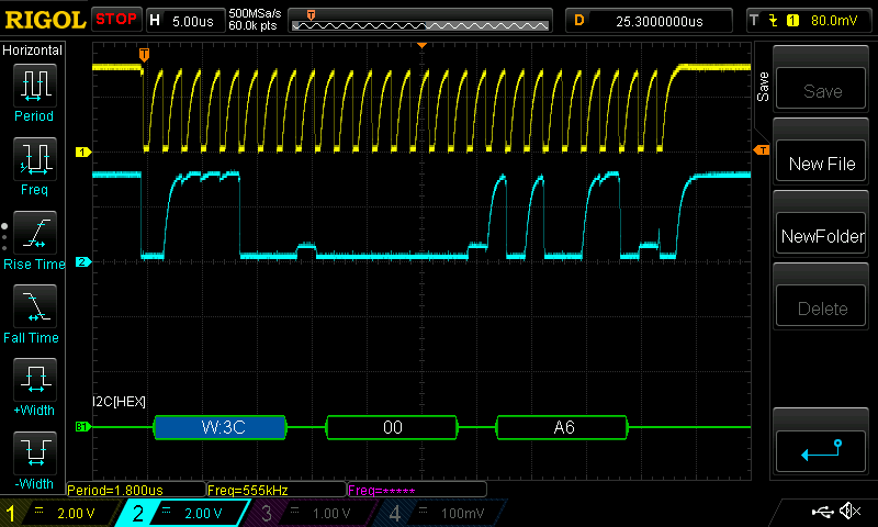
Here what i can see on my oscilloscope. It seems OK...

Now, i configure my I2C bus :

P2SEL0 |=  BIT5 | BIT6;                                    // Set P2.5,P2.6 to UCB0SCL, UCB0SDA
UCB0CTLW0 |=  UCSWRST;                                     // Enable SW reset
UCB0CTLW0 |= UCMST | UCMODE_3 | UCSYNC | UCSSEL__SMCLK;    // I2C Master, SMCLK
UCB0BRW_L = 10;                                            // Divide SMCL by 10 >> 400 kHz
UCB0BRW_H = 0;
UCB0I2CSA = 0x3C;
UCB0CTLW0 &= ~(UCSWRST);
UCB0IE |=  UCTXIE;

But with this code, my oled screen doesn't work because data are not correct.

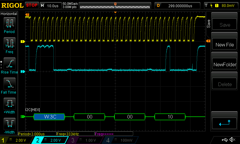
If i check with my oscilloscope, i obtain 333 kHz clock with frequency divider 10, and 4 MHz / 10 is not equal to 333 kHz ???

And if i test with divider 2 (UCB0BRW_L = 2), it works !!! But i obtain a frequency of 555 kHz (while my oled screen has a frequency max of 400 kHz), and the frequency is not equal to 4 MHz / 2 ???

I must be missing something here...

Do you have an idea ?

Thank you :-)

Christophe

  • Hello Christophe,

    I was unable to replicate your issue with a very similar device (MSP430F67791A), can you please try the following initialization code I used?

        WDTCTL = WDTPW | WDTHOLD;                         // Stop WDT
    
        // Setup UCS
        UCSCTL3 |= SELREF_2;                   // Set DCO FLL reference = REFO
        UCSCTL4 |= SELA_2;                     // Set ACLK = REFO
    
        __bis_SR_register(SCG0);               // Disable the FLL control loop
        UCSCTL0 = 0x0000;                      // Set lowest possible DCOx, MODx
        UCSCTL1 = DCORSEL_5;                   // Select DCO range 16MHz operation
        UCSCTL2 = FLLD_1 | 243;                // Set DCO Multiplier for 8MHz
                                               // (N + 1) * FLLRef = Fdco
                                               // (243 + 1) * 32768 = 8MHz
                                               // Set FLL Div = fDCOCLK/2
        __bic_SR_register(SCG0);               // Enable the FLL control loop
    
        // Init clocks : MCLK = SMCLK = 8 MHz, ACLK = 32768 Hz.
        UCSCTL4 = SELA__XT1CLK | SELS__DCOCLKDIV | SELM__DCOCLKDIV;// Divide SMCLK by 2 > 4 MHz.
        UCSCTL5 |= DIVS__2;
    
        // Worst-case settling time for the DCO when the DCO range bits have been
        // changed is n x 32 x 32 x f_MCLK / f_FLL_reference. See UCS chapter in 5xx
        // UG for optimization.
        // 32 x 32 x 8 MHz / 32,768 Hz = 250000 = MCLK cycles for DCO to settle
        __delay_cycles(250000);
    
        // Loop until XT1, XT2 & DCO fault flag is cleared
        do
        {
            UCSCTL7 &= ~(XT2OFFG | XT1LFOFFG | DCOFFG);
            // Clear XT2,XT1,DCO fault flags
            SFRIFG1 &= ~OFIFG;                 // Clear fault flags
        } while (SFRIFG1 & OFIFG);             // Test oscillator fault flag
    
        // Setup P2.5 UCB0SCL, P2.6 UCB0SDA
        P2SEL0 |= BIT5 | BIT6;                             // Set P2.5,P2.6 to UCB0SCL, UCB0SDA
    
        // Setup eUSCI_B0
        UCB0CTLW0 |= UCSWRST;                             // Enable SW reset
        UCB0CTLW0 |= UCMST | UCMODE_3 | UCSYNC | UCSSEL_2;         // I2C Master, use SMCLK
    
        UCB0BRW_L = 10;                                   // fSCL = SMCLK/12 = ~100kHz
        UCB0BRW_H = 0;
        UCB0I2CSA = 0x48;                                 // Slave Address is 048h
        UCB0CTLW0 &= ~UCSWRST;                            // Clear SW reset, resume operation
        UCB0IE |= UCTXIE0;                                // Enable TX interrupt

    Are you using a MSP-TS430PEU128 or a custom board?  Also, what pull-up resistance values are you using?  Your oscilloscope shots seem to indicate a slow rise time.

    Regards, Ryan

  • Hello Ryan,

    Sorry for my late return.

    Indeed, i'm using an MSP-TS430PEU128 and also an EXP430F5529LP.

    My code and my display work well with the 5529 but not with the 6779A. The EXP430F5529LP has an XT2 at 4 MHz which i use for SMCLK. Perhaps the problem comes from here because with the TS430PEU128, i'm obliged to use the XT1 at 32kHz to obtain my frequency of 8 MHz. Perhaps i do something wrong that i didn't understand.

    Anyway, there's something i don't understand with the dividers. With the 5529 which drives correctly my display, i experimented this dividers with SMCLK at 4 MHz :

        - 0x28 > 40 ==> I2C frequency at 96 kHz so correct and works :-)
        - 0x0A > 10 ==> I2C frequency at  333 kHz while i would obtain 400 kHz ???
        - 0x08 > 08 ==> I2C frequency at 400 kHz while i would obtain 500 kHz ???

    Actually, my display works at 400 kHz with divider at 0x08 but i don't understand the behavior. Do you have an explanation ?

    For my pull-up resistances, it's better with 4,7kOhm than 10kOhm. Thank you for the comment :-)

    Christophe

  • Hello Christophe,

    So you are having divider issues with both units? This indicates a firmware error, I would use the IDE debugger to ensure that the UCBxBRW register (among others) is being properly set with the expected divider value.

    Regards,
    Ryan

**Attention** This is a public forum