This thread has been locked.

If you have a related question, please click the "Ask a related question" button in the top right corner. The newly created question will be automatically linked to this question.

Interfacing transistor with MSP430

Hi,

I have a question regarding interfacing a transistor with a MSP430 as a switch for a led strip.

I dont have any previous experience with transistors and was wondering if anyone could offer some guidance as i would not like to fry another msp430 device and would like to ensure that my circuit is safe and will not cause any overheating and cause a fire while in use.

- I am using an MSP430 launch pad.

- A NPN Bipolar transistor (TO-220).  Can handle up to 6A and 100V and minimum gain of 15 mA

- 12V Led single colour strip. each strip requires 600mA.

 - Led strip powered using 12v wall socket adaptor. 

I am using this circuit as a guide but would like to double check. 

Image result for led strip microcontroller transistor

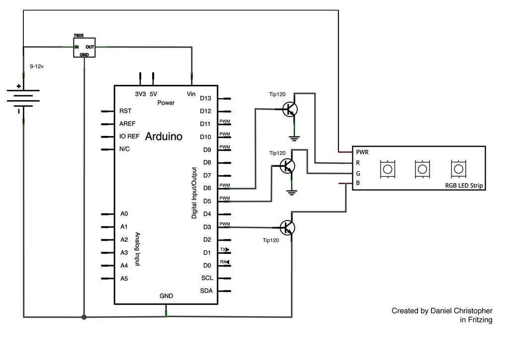
I have the same set up with:

Transistor:

Pin 1 (Base) - to microcontroller (but i have included a base resistor not 100% sure on the value).

Pin 2 (Collector) - to negative pin of led strip ( I am unsure if a resistor is necessary or not)

Pin 3 (Emitter) - to ground

Led strip:

- Positive lead to 12V

- Negative lead to pin 2 or collector pin of collector

I think i have figured out a value for a base resistor but again would like to double check.

Require 600mA per strip, double the current requirement to be safe. Run calculations for 1200mA.

Base current = collector current / current gain

(worst case scenario gain is 15mA)

IB = 1200mA / 15mA  = 80mA

I need to provide at least 80mA to the base of the transistor.

RB = (VCC - VBE) / IB


Vbe = 0.7V for a silicon transistor and Vcc is 3.3V

therefore 

(3.3 - 0.7) / 80 = 0.035 ohms

Needs to be multiplied by 1000.

Base resistor = 35 0hm 

Please let me know if i have made any mistakes or miscalculations. I appreciate anyone taking the time out to assist me in ensuring my circuit is safe thankyou. 

  • Perhaps you could identify the part number of the transistor and LED strip you are using so that we can verify your setup.

    That being said, you aren't going to get 80 mA of drive current out of the MSP430 I/O pin. If you really need 1.2 Amps of collector current, you need either a higher-gain bi-polar transistor, or a darlington arrangement transistor, or consider using an N-Channel MOSFET transistor (voltage switched instead of current switched). No matter the option, you need a power transistor and not a small-signal device.

    You mentioned about a collector resistor - that depends on the LED light strip. Does it have current limiting resistors at each LED? If so, you most likely don't need a collector resistor (or drain resistor if you go the MOSFET route).

    Personally - I would recommend a MOSFET, something like a Fairchild FDS6574A or any of thousands of others (check Digi-Key and Mouser).
  • Ok - I just saw that you have a TIP120 device (small image, didn't see that detail) - so that is a darlington device in a power package. Checks off 2 of my original concerns.

    Yes you need a base resistor to limit the current out of the I/O pin. Otherwise you are trying to put 3.3V against the approximate 1.4V of the stacked base voltages.

    Vbe-on is 2.5V, so 3.3V - 2.5V = 0.8 volts across the base resistor. hFE = 1000, so 1200 mA / 1000 = 1.2 mA. Then, R = V/I = 0.8 / .0012 = 667 Ohms.

    Standard resistor values (5%), use 680 Ohms.
  • Thankyou for the reply Brian.

    I now see that using a gain of 15mA in this case is not feasible as the MSP430 can only source 6mA, not even close to 80mA. A gain of 200 would be correct but i intend to use maybe 3 led strips which would increase my required current and i would have to increase the gain again so that is not an option.

    The led strip is from component shop and yes there are current limiting resistors at at each led so a collector resistor is not needed.

    My apologies for the image above, they are not ones that i own or have any of the same parts i was only using it as a rough guide to work from.

    I will purchase a TIP 120 device and include it in my circuit as the image above and also include a 680 ohm base resistor.

    Thank you for clearing up a lot of the confusion i was having with this circuit, much appreciated.

**Attention** This is a public forum