This thread has been locked.

If you have a related question, please click the "Ask a related question" button in the top right corner. The newly created question will be automatically linked to this question.

ESI signal observation on FR6989 ESI module.

Other Parts Discussed in Thread: MSP430FR6989

Hello Sir,

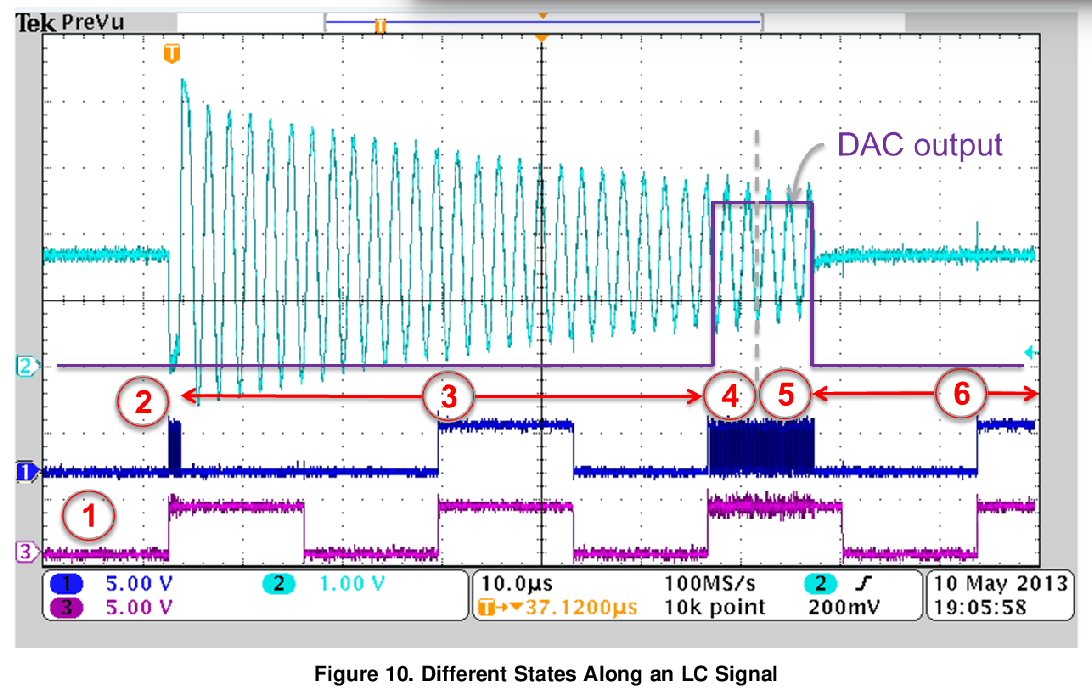
For waves mentioned in "slaa639_LC Sensor Rotation Detection With MSP430™ Extended Scan" as below:

We think, channel 3 should be ACLK and channel 2 measures the LC sensor signal. But seems no clearly description about what signal on Channel1.

Would you please help tell what signal shown on channel 1? Via any pin we can obsearve this signal with scope?

Best regards

Jacky

  • Hi Jacky,

    Channel 1 in Figure 10 appears to be capturing the TSM (timing state machine) clock signal.

    After analyzing the initial settings of the TSM registers shown in Section 4.5 in SLAA639, Point 2 in Figure 10 shows 5 cycles of the TSM clock sourced from the high frequency clock source. At Point 3, the TSM clock is sourced by the low frequency clock, ACLK.

    To observe this signal on a scope, you can utilize the ESITEST4 pin by selecting the TSM clock signal with the ESITEST4SEL bits in the ESIPSM register. Please see Section 31.3.16 and Figure 31-13 (shown below) in the User's Guide.

    Please let me know if you have any more questions.

    Regards,

    James

    MSP Customer Applications

  • Clearly, thanks.

    Jacky
  • Hi,

    Is it possible to see DAC output on the scope? If so, how can we do this?

    Regards,
    Alper
  • Hello,

    As you can see in Figure 37-2 in the User's Guide, the 8-bit MSB portion of the DAC output is connected to the ESITEST1 pin. Looking at the datasheet for the MSP430FR6989, this corresponds to P9.1.

    The TSM will need to be configured to make sure the internal DAC of the ESI module is always on, but this is possible. I've attached some sample code which should allow you to monitor the voltage on P9.1. For the configuration in the sample code, the voltage increases approximately every second.

    msp430fr69xx_esi_dac.c
    /* --COPYRIGHT--,BSD
     * Copyright (c) 2014, Texas Instruments Incorporated
     * All rights reserved.
     *
     * Redistribution and use in source and binary forms, with or without
     * modification, are permitted provided that the following conditions
     * are met:
     *
     * *  Redistributions of source code must retain the above copyright
     *    notice, this list of conditions and the following disclaimer.
     *
     * *  Redistributions in binary form must reproduce the above copyright
     *    notice, this list of conditions and the following disclaimer in the
     *    documentation and/or other materials provided with the distribution.
     *
     * *  Neither the name of Texas Instruments Incorporated nor the names of
     *    its contributors may be used to endorse or promote products derived
     *    from this software without specific prior written permission.
     *
     * THIS SOFTWARE IS PROVIDED BY THE COPYRIGHT HOLDERS AND CONTRIBUTORS "AS IS"
     * AND ANY EXPRESS OR IMPLIED WARRANTIES, INCLUDING, BUT NOT LIMITED TO,
     * THE IMPLIED WARRANTIES OF MERCHANTABILITY AND FITNESS FOR A PARTICULAR
     * PURPOSE ARE DISCLAIMED. IN NO EVENT SHALL THE COPYRIGHT OWNER OR
     * CONTRIBUTORS BE LIABLE FOR ANY DIRECT, INDIRECT, INCIDENTAL, SPECIAL,
     * EXEMPLARY, OR CONSEQUENTIAL DAMAGES (INCLUDING, BUT NOT LIMITED TO,
     * PROCUREMENT OF SUBSTITUTE GOODS OR SERVICES; LOSS OF USE, DATA, OR PROFITS;
     * OR BUSINESS INTERRUPTION) HOWEVER CAUSED AND ON ANY THEORY OF LIABILITY,
     * WHETHER IN CONTRACT, STRICT LIABILITY, OR TORT (INCLUDING NEGLIGENCE OR
     * OTHERWISE) ARISING IN ANY WAY OUT OF THE USE OF THIS SOFTWARE,
     * EVEN IF ADVISED OF THE POSSIBILITY OF SUCH DAMAGE.
     * --/COPYRIGHT--*/
    //******************************************************************************
    //
    //                     MSP430FR6989
    //                  -----------------
    //            RST -|             P9.1|--> DAC_output_voltage
    //                 |                 |
    //                 |                 |
    //                 |                 |
    //                -|LFIN             |
    //     32KHz XTAL  |                 |
    //                -|LFOUT            |
    //                 |                 |
    //
    //******************************************************************************
    #include <msp430.h>
    
    void ESI_init(void);
    void gpio_config(void);
    void clk_init(void);
    
    int main(void)
    {
    	unsigned int i;
    
        WDTCTL = WDTPW | WDTHOLD;
    
        gpio_config();
        clk_init();
        ESI_init();
    
        while(1)
        {
        	// Increases DAC voltage by ~ ((0.8*Vcc)/2^8)
        	// DAC voltage range Vss - (0.8*Vcc)
        	for(i=0;i<0x1000;i+=0x10)
        	{
        		ESIDAC1R0 = i;
        		_delay_cycles(8000000);
        	}
        }
    
    }
    
    void gpio_config(void)
    {
    	// Configure P9.4 and P9.5 as input pin in ESICH0 and ESICH1 mode
    	P9SEL1 |= BIT1;
    
    	// Configure PJ.4 and PJ.5 for 32kHz crystal on LFXT
    	PJSEL0 = BIT4 | BIT5;
    
    	// Disable the GPIO power-on default high-impedance mode to activate
    	// previously configured port settings
    	PM5CTL0 &= ~LOCKLPM5;
    
    }


    void clk_init(void)
    {
        // Configure Clock System Setup
        CSCTL0_H = CSKEY >> 8;                  // Unlock CS registers
        CSCTL1 = DCOFSEL_6;                     // Set DCO to 8MHz
        // Set SMCLK = MCLK = DCO, and ACLK = LFXT
        CSCTL2 = SELA__LFXTCLK | SELS__DCOCLK | SELM__DCOCLK;
        CSCTL3 = DIVA__1 | DIVS__1 | DIVM__1;   // Set all dividers to 1
        CSCTL4 &= ~LFXTOFF;
    
        do
        {
          CSCTL5 &= ~LFXTOFFG;                  // Clear XT1 fault flag
          SFRIFG1 &= ~OFIFG;
        } while (SFRIFG1 & OFIFG);              // Test oscillator fault flag
    
        CSCTL0_H = 0;                           // Lock CS registers
    }
    
    
    void ESI_init(void)
    {
        // start trigger of ACLK
        ESITSM = ESITSMTRG_1;
    
        // Timing State Structure initialization
        // TSM State 0 (Idle) configuration
        // In idle mode ACLK is fed to ESI module. Everything is disabled
        ESITSM0 |= (ESICLK + ESISTOP+ ESIDAC);
    
        // Enable ESI module
        ESICTL |= (ESIEN);
    
    }


    Hopefully this helps.

    Regards,

    James

    MSP Customer Applications

  • Thank you so much James,

    Regards,
    Alper
  • Hi James,

    We actually want to repeat a scenario shown at Figure.10 (above figure) but unfortunately DAC output i.e. ESITEST1 channel gives constant approximately 1.6V even if we change ESIDAC registers in the orginal code (www.ti.com/.../TIDM-LC-WATERMTR). When we modify the code that you sent so as to excite LC sensor, the amplitude of both LC sensor and ESITEST1 channel increases at the same time. How can we see DAC output while LC oscillator freely oscillate as in case of Figure.10 (above figure)?

    Regards,
    Alper
  • Hello Alper,

    There seems to be some misunderstanding about how the DAC is utilized by the ESI module. The DAC should output a constant value (reference voltage) to the comparator based on the necessary analog hysteresis for the upper level and lower level. Are you trying to view the output voltage from the excited LC sensor that gets input to the ESI module? If that's the case, you can just probe the output of the LC sensor. The internal DAC is used by the comparator to generate a digital value of the analog input.

    The code shared above demonstrates how the DAC output voltage can be manually changed. This demonstration highlights the operation of the DAC and should not be confused with how it's utilized when used by the ESI module.

    Does this make sense?

    Regards,

    James

    MSP Customer Applications
  • Hi James

    As i understood, DAC and comparator outputs are enabled via ESITSMx registers. ESIDAC1R0 and ESIDAC1R1 are responsible for creating voltage hysteresis. Hence we expect to see one of the DAC outputs on ESITEST1 when we enable DAC in the ESITSMx register. Can't we observe it? Our aim was to understand sample code that TI provides at www.ti.com/.../TIDM-LC-WATERMTR. This code utilizes DAC output frequenty (e.g to measure LC signal level or calibration purposes) and it is hard to track every step without seeing both voltage from excited LC sensor and DAC output on the oscilloscope.

    Thanks & Regards,
    Alper
  • Hi James

    Is it possible to see DAC output on the ESITEST1 channel while TSM running?

    Regards
    Alper

**Attention** This is a public forum