This thread has been locked.

If you have a related question, please click the "Ask a related question" button in the top right corner. The newly created question will be automatically linked to this question.

MSP430FR5989 / MSP430FR5986 current consumption issue over temperature

Other Parts Discussed in Thread: MSP430FR5989, MSP430FR5986, TIDM-LC-WATERMTR, EVM430-FR6989, MSP-FET, MSP430F5528

Current consumption ISSUE


We are working on MSP430FR598X based prototypes and we are having some issues related to current consumption over temperature change.

Up to now, we have already developed two different prototypes using both, MSP430FR5989 (Ver 1) and MSP430FR5986 (Ver 2).


Our application is using LC sensing hardware with two external resonant circuits following this AN:

Water Meter Reference Design for two LC Sensors, Using Extended Scan Interface (ESI): http://www.ti.com/tool/TIDM-LC-WATERMTR


Our FW is using this main routines (ESI_INV_CAL_V1_IIC):

-          void InitScanIF(void);

-          void ReCalScanIF(void);

-          __interrupt void ISR_ESCAN_IF(void)


The used resonant circuit is: 2x (1mH + 470pF)


When the FW is running in standby (no metal presence) we have a mean current consumption of about 3.8uA. Approaching metal to LC resonant circuit, excites a state change and MSP raises the current consumption up to about 10-20uA for short time going down again to 4uA.


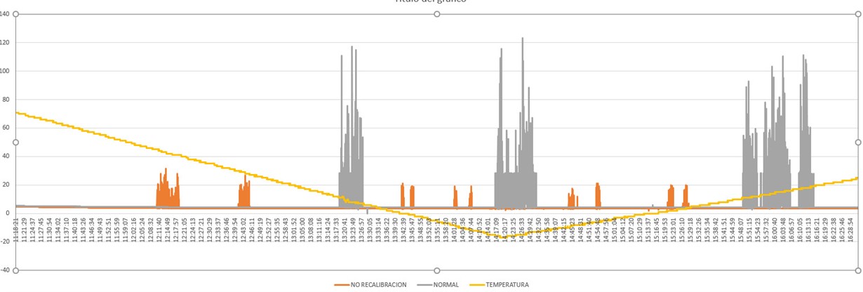
The fact is that we have tested in climatic chamber over the temperature range (+70ºC to -20ºC) and we have detected that MSP current is not stable at 4uA. We have registered the current consumption of 2 boards over temperature (one with recalibration routine active and other without) and there are current peaks without having any kind of reason.

We also have tested in sleep mode (no LC sensing) and the current stays stable at 4uA.

Knowing that, we have we have recorded a video where we have heated coils, capacitors and MSP (around LC sensing HW pins) and we have noticed that heating coils or capacitors has no effect and heating MSP current consumption rises.

https://vimeo.com/190095447


Have TI noticed this effect?

We have repeated this test with several prototypes from both versions and we have no pattern about when and how it is generated this effect.

We have plenty of tests done with current consumption records if needed.

Many thanks for your help!

Ruben

  • Hi Ruben,

    As stated in Section 2.4 & 5 of the Gas or Water Meter with Two LC Sensors TI Designs Guide (TIDU487), the TIDM-LC-WATERMTR firmware incorporates self-calibration to periodically check the system and adjust the DAC values of the continuously operating part of the ESI (to align it to the signal position of maximum reliability) if drift is found. This could include temperature drift as measured by the internal temperature sensor, which exits LPM to service an extended calibration ISR and creates the current spikes observed when the device is varied over temperature.

    Regards,
    Ryan
  • Good afternoon,
    I'm Rubén's partner

    As you tell us, in the section:

    2.4 Self-Calibration for Long-Term Operation
    Due to the temperature, humidity, aging components, and signal drifts, a continuous adjustment circuit is
    necessary to ensure the system is within the range of reliable operation. The ESI has a duplicated circuit
    inside, which can be used for detecting the overall drift of the system. This circuit will only be activated
    periodically to save power consumption. Once the drift is found, the circuit adjusts the DAC values of the
    continuously operating part of the ESI to align it to the signal position of maximum reliability.

    In non-metal presence conditions if the recalibration routine is executed by changes in temperature or humidity,
    does the ADC measure oscillate to detect changes in the state of the sensor inputs?

    In an afrimative case:
    If the recalibration routine was executed (without metal movement),
     There would be no changes in the calibration (obtained from the one between measurements with and without metal) right?

    Regards,

    Jose Miguel

  • Hello Jose Miguel,

    It is my belief that multiple calibration parameters are considered (ex. temperature and signal drifts from metal movement) and that the re-calibration of one variable does not reflect changes to the other. Changes in temperature require compensation to both the operating frequency and decay rate, as alluded to in SLAA639: www.ti.com/.../slaa639.pdf

    However I will try to bring in an ESI expert to further comment on this matter.

    Regards,
    Ryan
  • Hi Ryan,

    It would be awesome if an expert from TI could help us in this issue giving us more light.

    During the last tests we have made,  we have focused our scope on the MSP430 and the current consumption variations without any activity in the coils.

    We can conclude that temperature variations over MSP430 (we were heating only MSP) provokes LC amplitude variations, forcing a state change detection in the MSP. This state change wakes up the uC to evaluate the situation (peak of current consumption)

    Our equipment is non rechargeable battery powered and the election of the battery was based in a model where standby current (5uA) was the base and the current consumption related to activity was directly modeled by water meter counter lifetime (2 million of litre). Aging and temperature factor were also taken in count in this model.

    We have no idea how to model this temperature drift activity and it is very hard to take in count in the battery budget.

    Is it possible to disable this state change related to temperature or it is just a internal behaviour where nothing can be done?

    In case it is internal behaviour, how can we model this current consumption having the temperature profile?

    Sincerely analyzing all the experiments we have done over temperature (we have spent 4 weeks with climatic chamber tests) we have not found any kind of pattern between all the current consumption registers.

    I hope you can find the expert who could help us.

    Many thanks in advance

  • Hi Ruben,

    Have you been able to monitor the LC sensor oscillation variations across temperature? I believe that the current spikes you are observing are due to the fact that the MSP is waking up due to incorrect transition detection.

    Once you obtain oscillations variations there are somethings you might want to try:

    1. Analyze the the LC sensor oscillation variation and determine the type of frequency and amplitude oscillation changes you have across temperature.
    2. Based on the analysis of the LC sensor oscillation variations determine if the analog hysteresis in the ESI module need to be adjusted to minimize the effect of temperature on the coils.

    If adjusting the hysteresis of the ESI module does not solve the problem an alternative could be to develop a calibration routine using the msp internal temperature sensor and recalibrate the TSM registers and ESIDAC registers taking into account the ambient temperature.

    Regards,
    Ivan

  • Hello Ivan,

    Comments on obtaining variations of the oscillations to determine frequency and amplitude and thus adjust if necessary the analog hysteresis in the ESI module.

    The amplitude variations were observed on an oscilloscope by applying heat / cold directly on the MSP, but we do not have quantifiable data on the internal measurements of the MSP.

    We have performed tests on 4 circuits (without metal), with several temperature ramps and it has been observed that in all of them there are changes of state but in an apparently random way, that is to say at different temperatures, and also do not affect equally the MSP.

    The calibration and hysteresis (AFE1) we use consists of a mean between measurements with and without metal in the LC.
    The recalibration (AFE2) will adjust this calibration and hysteresis, if applicable, after n turns, but never otherwise.

    The reality is that if changes of state are detected both by changes in the detection or not of metal and also by temperature changes there is a risk that the counters ESICNT0, ESICNT1 and ESICNT2 count in error.

    We do not intend to perform a calibration adjustment without actual movement, what we want is to identify the wrong state changes (by temperature changes) to not take them into account.

    We know the problem, but not how to attack it. It should be noted that in reality the position of the needle (metal) on the LC can be any.

    What we want is to orient us to find a solution. In the event that we had to enhance medications such as making and registering.

    By way of example, so that you know with what data we move, a real calibration would be:
    Measurements (means):
    Channel 0:           Channel 1:
    Metal: 0x730        Metal: 0x736
    Air:      0x646        Air:      0x64A
    Hysteresis = 12

    Calibration (average Air - Metal +/- (Hysteresis / 2):
    Channel 0:                     Channel 1:
    ESIDAC1R0: 0x6B5     ESIDAC1R2: 0x6BA
    ESIDAC1R1: 0x6C1     ESIDAC1R3: 0x6C6


    Regards,
    Jose Miguel

  • Hi Ivan and Ryan,

    We have been analysing the LC signal behaviour while it is heated/cold.

    We have just noticed that internally MSP430 is triggering the ISR when it is not supposed to be interrupting.


    Knowing that our board and our software has been developed by us, we have tried to do the temperature cycle in the climatic chamber with the EVM430-FR6989 ESI FLow EValuation Module provided by TI with the original FW provided also by TI:

    Water Meter Reference Design for two LC Sensors, Using Extended Scan Interface (ESI) in

    « www.ti.com/.../TIDM-LC-WATERMTR Documents »


    We have modified the original FW just to have the counter of how many times the ISR is triggered during the temperature cycle.

    For testing purpose, we have modified as follows (Attached documents):

    -           Main.c

    -          ScanIF.c


    With this modification, LCD shows:

    -          First line:             rotation_counter

    -          Second line:       interrupt_counter


    All the added or modified code lines contains // JMM interrupt_Counter to easily find out.


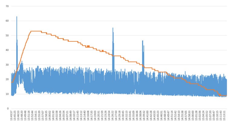
    During the following temperature cycle, we have registered about 400 undesired interruptions (see trace image):

    -          Yellow trace: temperature

    -          Blue trace: current consumption


    In terms of ISR counting register:

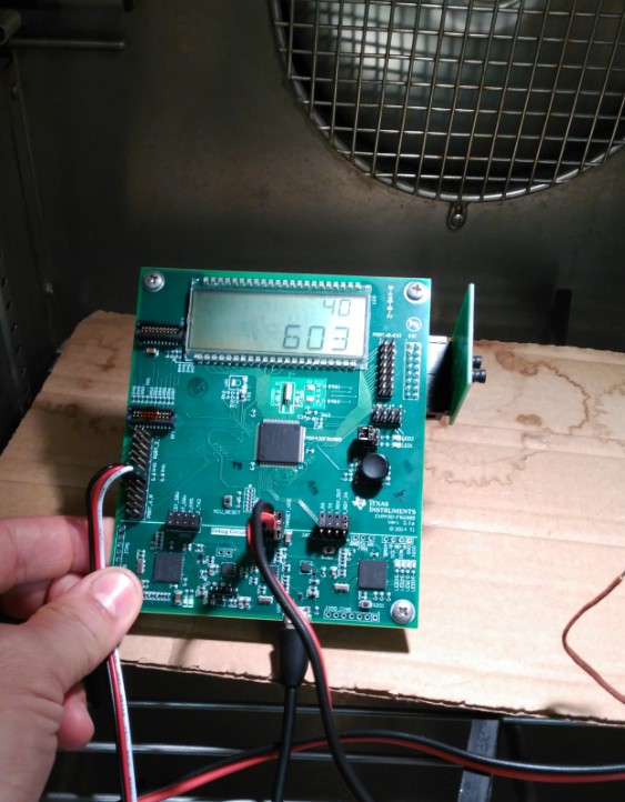
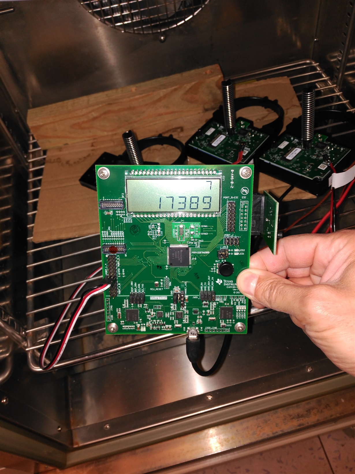
    -          ISR Initial Counter: 204

    -          ISR Final Counter: 603 (see attached image)


    As you can imagine, we are not able to put this equipment in production (we have manufactured the second prototype phase and we are just to launch first production) as far as we cannot model this behaviour.

    This equipment is battery powered and having this uncontrolled ISR enter with the associated current consumption, forces us not to continue manufacturing and trying to work around it.

    Unless we are not able to solve this issue, we will be forced to choose another platform from another vendor which fulfils our needs.


    Many thanks for your comprehension.


     ScanIF.C

    0777.main.c
    /*
     * This code is a reference design for rotational flow meter with 2 LC sensors
     * An I2C cable is used to link up the Main board and motor board.
     * An Auto process to will be started once the boards are powered up.
     * The main board will undergo Auto TSM setting, and optimize the reference voltage setting for DAC.
     *
     * The number of rotation  detected by ESI will be displayed in the lower digits of the LCD,
     * while the upper digits will display the rotation number from motor board. The data is sent via the I2C.
     *
     * When measuring the current consumption, remove all jumpers of the main board except for the jumper of GND above J401.
     * and tap the current meter to the jumper 3V3.
     * To measure the current consumption of ESI, without LCD and I2C,
     * press the black button on the main board and remove the I2C cable.
     *
     * To turn on the LCD again, press the black button to toggle it.
     *
     * Texas Instruments
     *
     * Author: Thomas Kot
     * Date  : July 2014
     *
     *
     */
    
    
    #include "msp430fr6989.h"
    #include "LCD.h"
    #include "ScanIF.h"
    #include "ESI_ESIOSC.h"
    #include "IIC.h"
    
    #define Time_out  8192      					// 2 sec for time out of Recalibration
    #define Time_to_Recal 8192  					// 2 sec for testing use, 40960 for 10 sec
    
    extern 	unsigned char  Status_flag ;
    char Power_measure = 0;
    signed int  test_status = 0;
    unsigned char ReCal_Flag ;
    
    int  rotation_counter = 0;
    int  interrupt_counter = 0;// JMM interrupt_Counter
    
    unsigned int Record_INT1=0;
    unsigned int Record_INT2=0;
    unsigned int Record_INT3=0;
    unsigned int Record_INT4=0;
    
    
    void Set_Clock(void);
    void Port_Init(void);
    void Set_Timer_A(void);
    void Check_debug(void);
    void Disable_all_IE(void);
    void Enable_all_IE(void);
    
    void Port_Init()
    {
    /*
     * This is to set the I/O port in the initialization.
     * The power consumption will be 0.8uA in LPM4 after setting.
     *
     */
    	P1DIR=0xFF;
    	P1OUT=0;
    
    	P1DIR &= ~BIT2;
    	P1REN |= BIT2;
    	P1OUT |= BIT2;
    
    	P2DIR=0xFF;
    	P2OUT=0;
    	P3DIR=0xFF;
    	P3OUT=0;
    	P4DIR=0xFF;
    	P4OUT=0;
    	P5DIR=0xFF;
    	P5OUT=0;
    	P6DIR=0xFF;
    	P6OUT=0;
    	P7DIR=0xFF;
    	P7OUT=0;
    	P8DIR=0xFF;
    	P8OUT=0;
    	P9DIR=0x00;
    	P9OUT=0;
    	P10DIR=0xFF;
    	P10OUT=0;
    	PJDIR=0xFF;
    	PJOUT=0;
    
    	CECTL3 = 0xFF00;
    
    	PM5CTL0 &= ~LOCKLPM5;;        				// In initialization, the I/Os are configured before unlocking the I/O ports
    
    	PMMCTL0_H = 0xA5;
    //	PMMCTL0_L |= PMMREGOFF;
    	PMMCTL0_L &= ~SVSHE;
    	PMMCTL0_H = 0xEE;
    
    }
    
    void Set_Clock(void)
    {
    // use external 32KHz crystal
    // MClock and SMClock from DCO 4MHz
    
    
          PJSEL0 |=  BIT4 + BIT5;					// using LFXTCLK
    	  CSCTL0 = 0XA500;                          // Write in the password for system clock setting
    	  CSCTL1 = 0x0006;                          // 4MHz for DCO
    	  CSCTL2 = 0x0033;                          // ACLK from LFXTCLK, SMCLK and MCLK from DCO
    	  CSCTL3 = 0x0000;							// ACLK div by 1, SMCLK div by 1, MCLK div by 1
    	  CSCTL4 = 0x0148;							// HFXTOFF, LFXTDRIVE = 1, VLO off, SMCLK on
    
    	  	 do
    	  	  {
    	  	    CSCTL5 &= ~LFXTOFFG;                // Clear XT1 fault flag
    	  	    SFRIFG1 &= ~OFIFG;
    	  	  }while (SFRIFG1&OFIFG);               // Test oscillator fault flag
    
    }
    
    
    void Set_Timer_A(void)
    {
    /*  This is the timer for triggering the run time re-calibration
     *  2 sec is set for demonstration purpose
     *  The actual timer setting depends on the application.
     */
    
    	TA0CTL = TASSEL0 + ID0 + ID1 + TACLR; 		//Aclk divided by 8;
    	TA0CCR0 = Time_to_Recal;              		// 2 sec for testing use
    	TA0CCTL0 = CCIE; 					  		// INT enable, INT flag cleared
    //	TA0CTL |= MC0;
    }
    
    
    void Disable_all_IE(void)
    {
    	Record_INT1 =  ESIINT1;
    	Record_INT2 = (TA0CCTL0&CCIE) ;
    	Record_INT3 = (UCB0IE &(UCTXIE | UCRXIE  | UCSTPIE | UCNACKIE));
    
    	ESIINT1 = 0x0000;
    	TA0CCTL0 &= ~CCIE;
    	UCB0IE   &= ~(UCTXIE | UCRXIE  | UCSTPIE | UCNACKIE);
    
    }
    
    void Enable_all_IE(void)
    {
       ESIINT1 = Record_INT1;
       TA0CCTL0 |= Record_INT2;
       UCB0IE   |= Record_INT3;
    
    }
    
    void main(void)
    {
    	WDTCTL = WDTPW + WDTHOLD;					// disable Watchdog
    
    	Port_Init();
    	Set_Clock();
    
    	P1IES |= BIT2;								// Set P1.2 as key input
    	P1IFG &= ~BIT2;								// User can press the black button to toggle switch on/off the LCD
    	P1IE  |= BIT2;
    
    	P1OUT |= BIT6 + BIT7; 						// for I2C pull up. For measuring current consumption, remove the physical I2C cable.
    
    //	__bis_SR_register(LPM4_bits+GIE);   		// un-remark this instruction. Engineer can measure the current consumption here. 0.7 to 0.8uA
    
    	init_LCD();
    	lcd_display_num(0,1);						// Display "0" on the upper digit which indicating the rotation number detected from infra-red sensor in motor board
    	lcd_display_num(0,0);						// Display "0" on the lower digit which indicating the rotation number detected from ESI
    
    
    	ReCal_Flag = 0;                 			// Init the status flag with non-runtime calibration
    
    	EsioscInit(ESIOSC_Default);       			// default setting = 4.8MHz for internal oscillator of ESI
    
    	Set_IIC();                      			// IIC setting
    	IIC_TX(0x00);								// ensure the motor is topped
    
    	InitScanIF();								// Initialization of ScanIf module
    	Status_flag |= BIT2;						// indicating Calibration of DAC process completed
    
    
    //	Disable_all_IE();							// These two routines are prepared for testing use, in case of Interrupt conflict
    //	Enable_all_IE();
    
    
    #if AFE2_enable
    	 Set_Timer_A();                				// set and start timer for triggering run-time re-calibration
    #endif
    
    interrupt_counter= 0;// JMM interrupt_Counter
    
    while(1)	                					// Infinite loop for demonstration purpose
     {
    	 ESICTL  &= ~ESIEN;							// Disable the ESI
    
    	 __delay_cycles(80);
    	 IIC_TX(0x00);             					// stop the motor rotation
    	 __delay_cycles(8000000);
    	 IIC_TX(0x30);             					// reset motor rotation counter
    	 lcd_display_num(0,1);                      // Set LCD to "0" for motor
    	 lcd_display_num(0,0);						// Set LCD to "0" for ESI
         __delay_cycles(8000000);
    
    
     	 ESIINT1 &= ~ESIIE5;
     	 ESICTL  |= ESIEN;            				// ESI enable. This will reset all counters of ESI. For actual operation of flowmeter, switch on ESI and will always on till battery drain off
     	 ESIINT2 &= ~ESIIFG5;                   	// clear INT flag of Q6 of PSM
    
    	 TA0CTL &= ~MC0;							// Reset Timer for runtime Re-calibration
    	 TA0CTL |= TACLR;
    	 TA0CTL |= MC0;
    	 ReCal_Flag = 0;
    
    	 IIC_TX(0x2F); 					        	// start motor clockwise rotation at 45 to 50 turns per second
    	 __delay_cycles(800000);
    
     	 ESIINT1 |= ESIIE5;							// enable INT of Q6
    
    
    	while(1)									// Demonstrate the 1000 rotations of rotor disc
    	{
    
    		if (test_status&BIT0)
    		{test_status &=~BIT0;                   // when 1000 rotations done, go to next cycle of 1000 rotations demonstration
    		break;									// and repeat it infinitely
    		}
    
    	    __bis_SR_register(LPM3_bits | GIE);   	// Enter into LPM3 and enable interrupts
    	                                            // keep in LPM3 until there is a rotation to trigger ESI Q6 interrupt
    
    
    #if AFE2_enable
    
    	if(ReCal_Flag&BIT6)							// Check if Re-calibration flag is set
    	{
    	  ReCal_Flag &= ~BIT7;                  	// Reset Bit7 for timer call
    
    	  TA0CCR0 = Time_out;                   	// set the time out timer. it will generate a time out interrupt when it stop rotating
    	  TA0CTL |= MC0;
    	  ESIINT1 &= ~ESIIE5;
    
    	  ReCalScanIF();           					// to do runtime calibration with AFE2
    
    	  TA0CTL &= ~MC0;
    	  TA0CTL |= TACLR;                      	// Reset Timer
    	  TA0CCR0 = Time_to_Recal;              	// Set the timer back for Re-calibration counting
    	  TA0CTL |= MC0;							// timer re-start for ReCal.
    
    	  ReCal_Flag = 0;							// ReCal of AFE1 is done, reset all flags.
    
    	  __bic_SR_register(GIE);					// Ensure no abnormal interrupt before entering LPM;
    	  ESIINT2 &= ~ESIIFG5;                  	// clear the Q6 flag
    	  ESIINT1 |= ESIIE5;						// Enable Q6 INT for in case of Time out.
    	}
    #endif
    
    
    	}
    }
    
    }


    #pragma vector=ESCAN_IF_VECTOR
    __interrupt void ISR_ESCAN_IF(void)
    {
       TA0CCTL0 &= ~CCIE;
    
       switch (ESIIV)
       {
       case 0x02:  if (ESIINT1&ESIIE1)
    				{ESIINT2 &= ~ESIIFG1;                 								// clear the ESISTOP flag
       	   	   	   	   if(ReCal_Flag&BIT6)
    					{TA0CTL |= TACLR;                   							// Reset Timer to prevent abnormal time out.
    					TA0CCTL0 &= ~CCIFG;	}
    
       	   	   	   	    TA0CCTL0 |= CCIE;
       	   	   	   	   	_low_power_mode_off_on_exit();     								// exit low power mode;
    				}
    			  break;
    
       case 0x04:  break;
       case 0x06:  break;
       case 0x08:  break;
    
       case 0x0A: break;
       case 0x0C: if(ESIINT1&ESIIE5)
       	   	   	   	   {    ESIINT2 &= ~ESIIFG5;                						// clear the Q6 flag
    interrupt_counter++;// JMM interrupt_Counter
       	   	   	   	   	   if(ReCal_Flag&BIT6)
    						{TA0CTL |= TACLR;                   						// Reset Timer to prevent abnormal time out.
    						TA0CCTL0 &= ~CCIFG;	}
    
    						if(ReCal_Flag&BIT7)
    						{ ReCal_Flag |= BIT6;	}           						// to do runtime calibration with AFE2
    
    						if(Status_flag&BIT2)                						// Check for completion of Calibration of DAC
    							{							    						// If yes, LCD is to display the rotation number
    							ESIINT1 &= ~ESIIE5;
    
    							 if(!(ReCal_Flag&BIT6))
    							 	 {
    									if (LCDCCTL0&LCDON)
    									{   IIC_RX();									// to get the number of rotation detected by motor board
    										rotation_counter = Master_RXData[1];
    										rotation_counter <<= 8;
    										rotation_counter += Master_RXData[0];
    // JMM interrupt_Counter									lcd_display_num(rotation_counter,1);        // to display the data from motor board in the upper digits of LCD
    									}
    							 	 }
    
    							ESIINT2 &= ~ESIIFG5;
    							ESIINT1 |= ESIIE5;
    
    
    						rotation_counter = ESICNT1;									// get the ESI counter for number of rotation
    							if (rotation_counter < 0)
    							{rotation_counter = -1*rotation_counter /4;}			// divided by 4 as the counter is increased by 1 for every state change of 2 LC sensor.
    							else													// which is set by PSM table
    							{rotation_counter = rotation_counter / 4;}
    
    // JMM interrupt_Counter					lcd_display_num(rotation_counter,0);						// to display the number of rotation from ESI in low digits of LCD
    lcd_display_num(rotation_counter,1);// JMM interrupt_Counter
    lcd_display_num(interrupt_counter,0);// JMM interrupt_Counter
    
    
    							if (rotation_counter > 1000)							// when number of rotation reaches 1000, it stop the motor
    								{													// User can then check the counting from ESI and Motor and see if they match.
    																					// There has a +/- 1 difference as the detector in motor board is not in the same physical position as that of LC sensors
    								    ESIINT1 &= ~ESIIE5;
    								    if (LCDCCTL0&LCDON) IIC_TX(0x00);				// send command to stop the rotor
    
    									 __delay_cycles(8000000);
    
    									 if (LCDCCTL0&LCDON)
    										 {
    										 	IIC_RX();
    											rotation_counter = Master_RXData[1];
    											rotation_counter <<= 8;
    											rotation_counter += Master_RXData[0];
    // JMM interrupt_Counter											lcd_display_num(rotation_counter,1);   	// to display the data from motor board in the upper digits of LCD
    										 }
    
    									rotation_counter = ESICNT1;
    										if (rotation_counter < 0)
    										{rotation_counter = -1*rotation_counter /4;}
    										else
    										{rotation_counter = rotation_counter / 4;}
    
    // JMM interrupt_Counter									lcd_display_num(rotation_counter,0);    		// to display the number of rotation from ESI in low digits of LCD
    lcd_display_num(rotation_counter,1);// JMM interrupt_Counter
    lcd_display_num(interrupt_counter,0);// JMM interrupt_Counter
    
    										 __delay_cycles(8000000);
    
    									 test_status |= BIT0;							// indication of completion of 1000 rotations
    
    								}
    
    							}
    
    						TA0CCTL0 |= CCIE;
    						_low_power_mode_off_on_exit();       						// exit low power mode;
       	   	   	   	   }
    
    	          break;
       case 0x0E: break;
       case 0x10: break;
       case 0x12: break;
       }
    
       TA0CCTL0 |= CCIE;
    
    }
    
    
    // Timer A0 interrupt service routine
    #pragma vector = TIMER0_A0_VECTOR
    __interrupt void Timer_A (void)
    {
        if (ReCal_Flag&BIT6)
        {
        	ReCal_Flag |= BIT1;                           								// Time out
    
        	ESIINT1 &= ~(ESIIE1+ESIIE5);				  								// Prevent entering ESI ISR to call an extra "_low_power_mode_off_on_exit()"
    
        	_low_power_mode_off_on_exit();       	      								// exit low power mode from ReCal_ScanIF ;
        }
        else
        {
        	ReCal_Flag |= BIT7;                   		 								// indicate the need to perform runtime calibration
        }
    
    	TA0CTL &= ~MC0;									 								// disable timer
    
    }


    // Timer A1 interrupt service routine for I2C time out timer
    #pragma vector = TIMER1_A0_VECTOR
    __interrupt void Timer1_A (void)
    {
    	TA1CTL &= ~MC_1;
    	Set_IIC();
    	__bic_SR_register_on_exit(LPM0_bits ); 											// Exit LPM0
    
    }
    
    
    // Port 1 interrupt service routine for push button of the main board
    #pragma vector=PORT1_VECTOR
    __interrupt void PORT1_ISR(void)
    {
        P1IFG &= ~BIT2;
        Power_measure ^= BIT0;
    
        if (Power_measure & BIT0)
        {LCDCCTL0 &= ~LCDON;
        ESIINT1 &= ~ESIIE5;																// disable INT of Q6
    	TA0CTL &= ~MC0;																	// stop the re-calibartion timer
        }
        else
        {LCDCCTL0 |= LCDON;
        ESIINT1 |= ESIIE5;																// enable INT of Q6
    	TA0CTL |= MC0;																	// turn on re-calibration timer
        }
    
       _low_power_mode_off_on_exit();
    
    }
    

  • Hi Ruben,

    As Ivan had mentioned earlier, the correct way to avoid incorrect state changes is to develop a calibration routine which takes into account a system calibration temperature and the current operation temperature. This is a typical problem with LC sensors application, and there is a application note from LDC team where they discuss temperature impact on inductance based designs: www.ti.com/.../snaa212.pdf

    Unless this temperature based calibration method is developed you will not be able to avoid incorrect state transitions. Ivan has agreed to spend some time next week to work on a temperature based calibration which should help to reduce the incorrect state transitions using the TI Design hardware, you will then need to learn from his example in order to further develop your own design.

    Regards,
    Ryan
  • Hi Ryan,

    The application note of the LDC1000 sensor confirms that temperature changes affect the resonance impedance and the inductance and therefore the oscillation frequency.

     According to this we have two problems with the temperature variation:

    - interruptions due to changes in state and therefore consumption.

    - it is more than likely that if the frequency changes can be counted wrongly.

    It is right?

     The solution (if it exists) would happen to readjust the oscillation frequency?


    In the application note "SLAA609A" in section

    "3 ESIOSC Measurement and Adjustment Software Functions"

    I have seen that it talks about to readjust ESIOSC in execution with the routine EsioscReCal ()


    The solution could be to use the EsioscReCal () routine?

    If so, when should it be applied?

    It should be noted that the counter needle can be in any position or rotating and it does not have to interfere with counting


    Let's hope that Ivan's tests give us a solution, without having to add a sensor (LDC1000) to our design.


    Regards,

    Jose Miguel

  • Hi all,

    We have been following with additional tests over temperature using TI Development Kit.

    In our first tests, we have used a high gradient temperature cycle (2 min per degree) which is not very common in our application.

    We have modified the cycle to have 2ºC/h, which is much more common.

    Starting at +20ºC we have reached +2ºC in 9-10h aproximately and the MSP kit had about 100 ISR entries counting at the starting point due to calibration process.

    With this profile we have realised that ISR false triggering had been increased hugely comparing to previous tests.

    We have also tested with our modules and ISR entries counter are in the same scale:

    DUT 1: 17533

    DUT2:  19866

    We are going to test it again in order to validate the test and have more data to analyse .

    I hope this results could give some more information to go further in your investigations about this issue.

    Many thanks

  • Hi Ivan and Ryan,

    Have you achieved to repeat the test with TI Dev Board in the climatic chamber?

    Have you had the same results as me?

    Our customer and us, we are getting worried about this issue because unless we do not have a possible workaround, we would not be able to send this project to production and we will be forced to look for another brand solution.

    Many thanks for your comprehension.

    Ruben

  • Hi Ruben,

    Ivan has been able to reproduce the issue using a EVM430-FR6989 and test chamber. He is currently validating a temperature calibration routine.

    Regards,
    Ryan
  • Reuben,

    I just wanted to let you know that Ivan is still working on this, but is out of office till January 3rd.

  • Hi,

    Do you have any kind of news?

    When do you expect to have something to test?

    Many thanks,

    Ruben

  • Ruben,
    We need to get profiles of of your LC tanks' oscillation frequency and amplitude changes over a range of temperatures. Can you put these together for 3-5 of your sensor boards?

    We have a working theory that temperature is effecting the oscillation characteristics of your sensors, such that the the oscillation threshold is crossed, a false state transition is detected, and therefor the interrupt is fired. This may somehow be aggravated by the calibration routine. We will be conducting some tests to help prove this on Monday morning CST.

    The idea is to establish temperature transition points at which the oscillation threshold needs to be re-calibrated to compensate for the thermal effects on the sensors. Temperature could be detected by using the internal temperature sensor.

    Another, less probable, solution is that we find a new oscillation threshold that works across the needed temperature range.

    Let me know if any of that is unclear.
  • Good morning Cameron & Ivan,
    Once the firmware is loaded in the Kit and after the calibration, a couple of captures are made on the oscilloscope.

    If you need some measure in the catch (amplitude in some point, etc) tell us.

    I want you to confirm that this is what you want to send you, before performing the tests in climatic chamber.

    Regards,
    Jose Miguel

  • Hi José Miguel,

    Yes, those are the oscillation we are looking for. Could you please obtain oscillations at -20C, 0 C, 20C, 40C and 60 C. With at least 3 different coils?

    Thank you,
    Iván

  • Good Morning,
    Sending the oscilloscope captures to different temperatures made to 3 modules + the kit.

    You can see in these captures how the signal changes.
    But without data (ADC) it is difficult to quantify.

    Would not it be better to perform ADC measurements for each temperature ???
    If so, you would have to modify the firmware of the Kit to display this measurement on the LCD. Perhaps using the pushbutton.

    You will comment
    Regards,20170113 MSP430FR5989 - Capturas Camara Climatica.zip

  • Hi Jose,
    I have your hardware. Can you send us your schematics?

  • Hi Cameron,

    I send you the schemes that you request

    regards,

    Jose Miguel20170119 SCH_PCB.ZIP

  • Hi Ivan and Cameron!

    Have you had time to check the schematics and signals sent?

    Do you need any further information?

    BR
    Ruben Hernandez
  • Hi Ruben!
    We have looked over the schematics. Thank you for those, it will help us to program the devices.
    We are currently investigating a possible temperature dependency of the ESI clock.
    We have also noticed that, on our TI-Design, if we simplify the firmware we begin to see the same issue. The original firmware does not exhibit the issue. We are seeking to understand what the key difference is.

    I hope to have more updates tomorrow afternoon.
  • Hi Cameron,

    Good to know you are close to the key point.

    I hope we could have good news soon and we could continue with the design.

    Good job!

    BR

    Ruben

  • Hi Ruben,

    We want to start testing some calibrations options on your board. However we are having problem re flashing the board. We have tried using 4-pin JTAG configuration and Spy-bi-wire configuration and both modes are failing.

    Could it be possible to get the correct procedure to reflash the boards. I am using the MSP-FET tool and CCS to reflash the board.

    Regards,
    Ivan

  • Hi Ivan,

    We use the MSP-FET430UIF tool and CCS (Code Composer Studio 6.2.0) to reflash the board.

    We use "Signal Connections for 4-Wire JTAG Communication".
    We have created an adapter the MSP-FET430UIF connector to the board.

    Attached images of scheme and adapter used.

    Regards,
    Jose Miguel

  • Hi Jose,

    Thank you for the information. Now I am able to load code to the board. 

    In my case it consistently takes 2 retries before the CCS is able to load the program.

    Regards,

    Ivan

  • Hi Jose,

    Please find an update below.

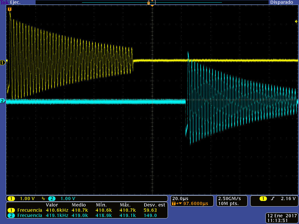
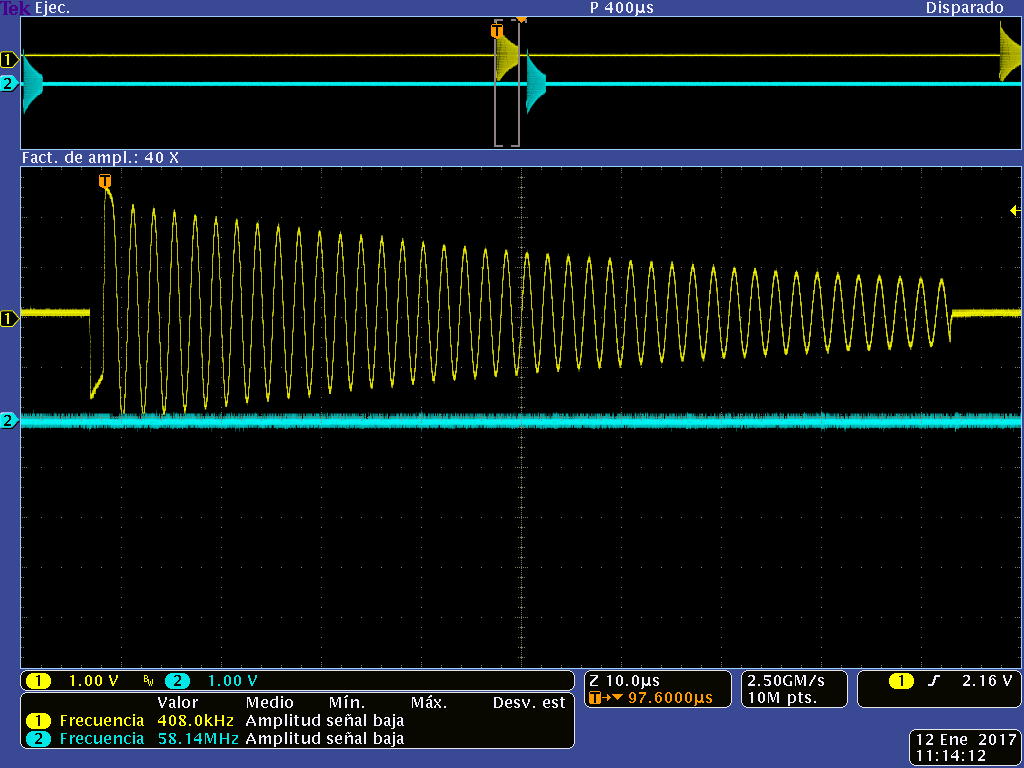
    The figure below shows the oscillation of the LC tanks in your design with out any type of re calibration.

    As you can observe in the figure above, changes in temperature will affect three main factors in the design:

    1. ESIOSC frequency will drift due to temperature changes. (This is shown in the circle in red). This is the reason the oscillation stops at different point in time.
    2. LC tank frequency drift due to temperature. This impacts the TSM calibration.
    3. LC tank decay rate increases at low temperatures. This impacts the ESI DAC configuration.

    Currently we have a fix for item #1. We have added a calibration routine which monitors the internal temperature of the MSP and triggers a recalibration of the ESIOSC when the temperature crosses predefined thresholds. The LC tank oscillation with ESIOSC recalibration can be observed in the figure below. Next week we will to tackle item 2 and 3.

    Regards,
    Ivan

  • Hi Ivan,

    Have you been able to follow with the two other issues?

    Do you need any kind of help?

    Thanks for your effort.

    Ruben

  • Ruben,
    We are still running a test. I'll have another update very shortly :-)
  • Good Morning Ivan & Cameron,

    How are the tests going?
    We know that testing requires time and that the algorithm will not be easy, but we are impatient.

    Expecting positive news about it.

    Best regards,
    Jose Miguel
  • Jose,
    I spoke with the rest of the team assigned to this issue today. We are making very good progress, current consumption has been mitigated. However we are still seeing some interrupt misfires. This has been speculated to be related to ice formation observed in the temp chamber. I will keep you updated. If you would like to have a call scheduled, let me know, but I think we are on track to having a complete solution very soon.
  • Good morning Cameron,
    We would like to know if there are any positive developments in the tests.

    The truth is that another week has passed without news, and we are impatient to receive news.

    Best regards,
    Jose Miguel

  • Hi Jose,

    I apologize for the delay, but we seem to have found a workaround for the sudden increase of current consumption. I am attaching a CCS project which we have tested in our temp chamber and we don't see the spikes in current consumption. Below are a list of modifications we did to the TI Design code.

    • Measure the temperature every 2s
    • Recalibrate the ESIOSC frequency. Correct the temperature influence on the ESIOSC
    • Set TSM value to sample the right point at each temperature range.
    • Check ESIDEBUG2_H to insure TSM is in IDLE state before any changing on the ESI registers. If not, it may cause TSM register corruption.
    • Enable OSC fault interruption stop sampling until the crystal works again. When there is a LFXT failure happening, it can cause the mis-triggering. Cause the ESIOSC is source by the ACLK and ACLK source by the LFXT, it samples at the wrong point again.

    Could you please load the code on the FR6989-EVM and let us know if the unexpected current spikes are gone across temperature?

    Regards,
    Ivan

    IKOR_Project_EVM2.zip

  • Good morning Ivan,
    I'm having trouble connecting the "EVM430-FR6989 Evaluation Kit" to the PC.

    When connecting to PC, the message:
    "USB device not recognized"

    It is tested with several USB connectors and on several PCs.


    Maybe something has crashed in the climatic chamber tests.

    Could you connect to the PC with MSP430-FET430UIF connecting J200 JTAG ???

    Any advice ?

    Best regards,
    Jose Miguel

  • Hi Jose,
    This usually means that there is something incorrect with the connection. Can you check your jumper settings? These are a common culprit.

    You should be able to connect using FET430UIF, are you seeing otherwise?
  • Hi Cameron,

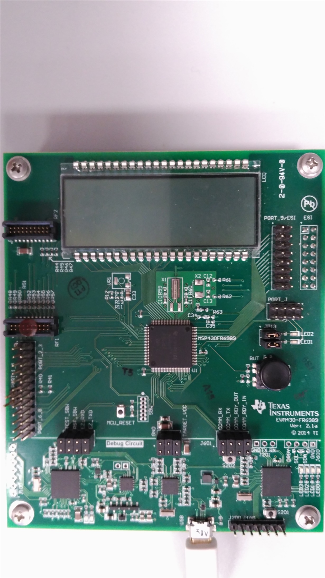
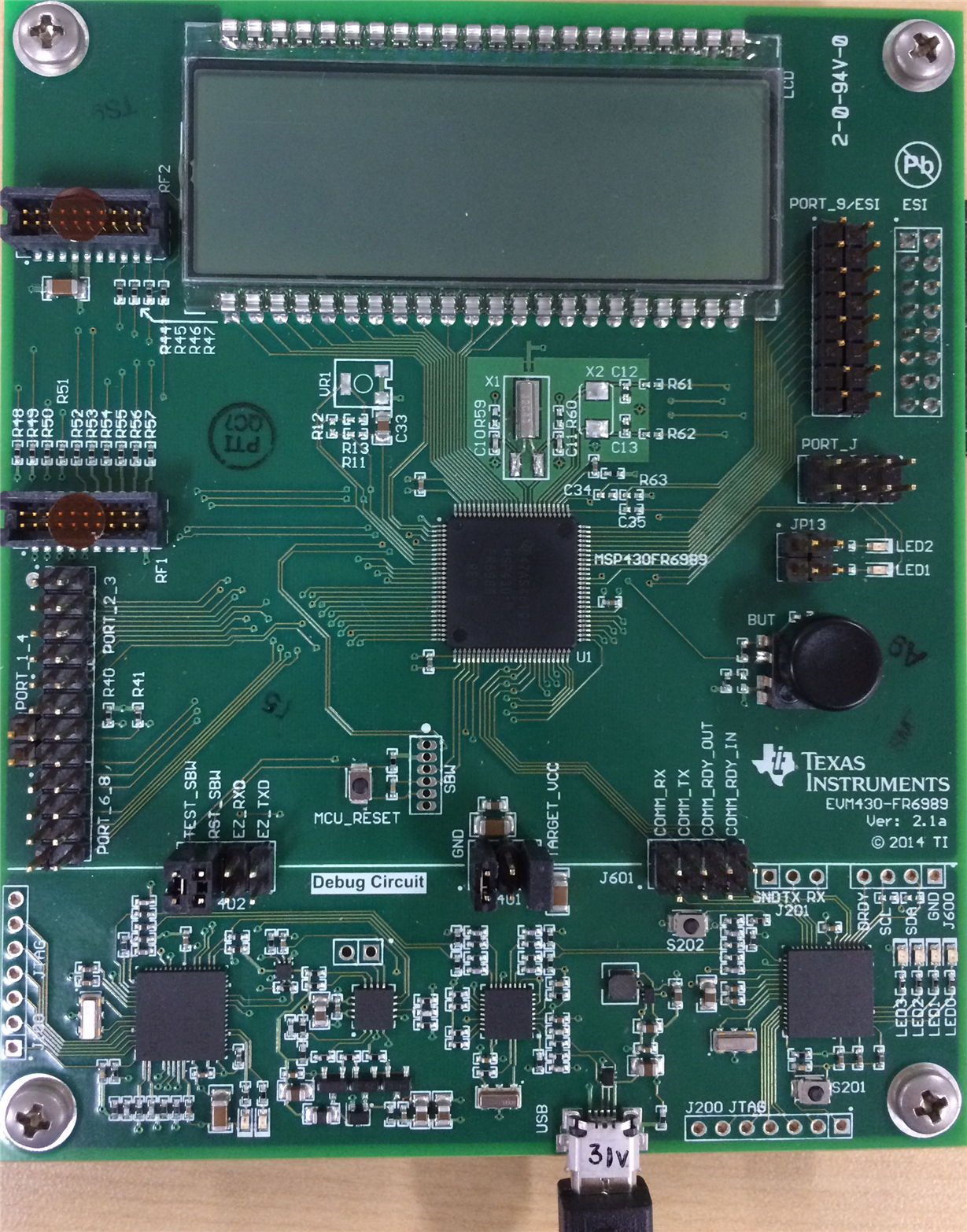
    Attached image of the "EVM430-FR6989 Evaluation Kit"

    I have tried removing jumper jumpers from J402 and J601 and some from J401. The report has been wrong.

    The "EVM430-FR6989 Evaluation Kit" was connected to the PC with USB-MciroUSB, but we had never connected through MSP-430FET430UIF.

    It asked if the firmware could be transferred to the kit via "MSP-430FET430UIF".

    I connected it through J200 (JTAG) without success since this JTAG goes to the "MSP430F5528 COMMUNICATIONS BRIDGE".

    Any suggestions?

    Do you have the test firmware implemented in our hardware?

    Best regards,

    Jose Miguel

  • Hi Cameron,

    Our firmware, as already mentioned, is an adaptation of (ESI_INV_CAL_V1_IIC - TI)

    ESI_INV_CAL_V1_IIC Firmware:

    This firmware performs an initial calibration, with 4 turns of a needle.

    And when there is movement, use the recalibration routine by adjusting

    ESIDAC1R0, ESIDAC1R1, ESIDAC1R2, ESIDAC1R3

    IKOR Firmware:

    In our firmware the calibration can not be done in the counter and is done with the average of the measurements of:

    1) Non-metal

    2) Metal with a tool

    With orders from the UART.

    The recalibration has not been modified and will be adjusted later when the module is in the counter.

    Consumption is about 5 uA, without needle movement.

    Firmware received IKOR_Project_EVM2.zip:

    In the firmware received "IKOR_Project_EVM2.zip" recalibration for setting by temperature changes:

    - Measure the temperature every 2s

    - Recalibrate the ESIOSC frequency. Correct the temperature influence on the ESIOSC

    - Set TSM value to sample the right point at each temperature range.

    - Check ESIDEBUG2_H to insure TSM is in IDLE state before any changing on the ESI registers. If not, it may cause TSM register corruption.

    - Enable OSC fault interruption stop sampling until the crystal works again. When there is a LFXT failure happening, it can cause the mis-triggering. Cause the ESIOSC is source by the ACLK and ACLK source by the LFXT, it samples at the wrong point again.

    Questions:

    - The new recalibration replaces the one recalibrated by ESIDAC1Rx. Ie ESIDAC1Rx not adjusted ??

    - "IKOR_Project_EVM2" is a test version for the "EVM430-FR6989 Evaluation Kit", or does it replace ESI_INV_CAL_V1_IIC ??

    - It is VERY IMPORTANT not to increase the consumption at rest. Have you taken this into account? ... To do this the temperature measurements should be performed every longer, right ???

    We have already been very late with the development of the firmware and for the project to be viable, the time begins to be critical.

    We expect news.

    Best regards,

    Jose Miguel

  • Hi Jose,

    If you want to download and debug the "EVM430-FR6989 Evaluation Kit". Please try to make the connectors just like the way it shows in my attachment.

  • Hi Jose,

    Please the

    Jose Miguel Martin Mateos said:
    - The new re-calibration replaces the one re-calibrated by ESIDAC1Rx. Ie ESIDAC1Rx not adjusted ??

    In the example project that was sent (IKOR_project_EVM2.zip),the initial calibration of the ESIDAC registers are configured using he ESI DAC calibration (ScanIF_Calibration_Set_DAC function). This is the default configuration in the project. If you wan to disable the DAC calibration you can manually set the ESIDAC registers by removing the comment in main.c in line 42 (#define APP_SET_DAC_MANUALLY).

    Jose Miguel Martin Mateos said:
    "IKOR_Project_EVM2" is a test version for the "EVM430-FR6989 Evaluation Kit", or does it replace ESI_INV_CAL_V1_IIC ??

    It replaces ESI_INV_CAL_V1_IIC, the idea is to provide a project (IKOR_project_EVM2.zip), which demonstrate how to reduce false triggers in the EVM430-FR6989 due to temperature changes, which then can then be added to your existing application.

    Jose Miguel Martin Mateos said:
    - It is VERY IMPORTANT not to increase the consumption at rest. Have you taken this into account? ... To do this the temperature measurements should be performed every longer, right ???

    Correct, in the sample project, the internal temperature is sampled every 2 sec, however it can be modified via the ESITEMPCAL_tempCal_configureTimer function in main.c to meet your average power consumption requirements. Do you know the rate at which the temperature vary in your application?

    Regards,
    Ivan

  • Hy Ivan,

    Regarding the "EVM430-FR6989 Evaluation Kit" Kit, I have put the connectors as indicated in the mail (I already tried that combination), as I mentioned, there is a problem in the Kit because the PC does not recognize the USB device.

    I have adapted our firmware with "IKOR_Project_EVM2" where I have modified the timing of the temperature readings from 2 "to 16".

    Follow up to 3 modules (calibrated and counting correctly at room temperature 25ºC)

    Climatic chamber tests were performed with two different profiles:
    - Rapid profile (total 2h45 '): Drop from 30ºC to -10ºC and rise to 30ºC with 2ºC / Minute.
    - Slow profile (total 15h15 '): Drop from 30ºC to -10ºC, rise to 65ºC and drop to 30ºC with 10ºC / hour.
    Tests have been repeated several times.

    The results of one of the tests were:
    First: No counting (no iron on the coils) to check for interruptions due to gAPP_interruptCounter status changes (and consumption peaks)
    - Quick profile: Interruptions in modules 5500, 6200, 2000
    - Slow profile: Interrupts in modules 59334, 9812, 22768

    Second: Modules on meters in rotation at different frequencies, to check counting.
    - Quick profile: The modules have been counted less (for example, in 22,000 laps, 1,000 less, 65,000 laps less than 14,000)
    - Slow profile: Modules have been counted less (eg in 100,000 laps, 43,000 less, in 747,000 laps 64,000 less)

    At the end of the test (at room temperature), sometimes modules, in the air (without iron in the coils) detect that they are with iron ???,
    And in this situation the cases have occurred:
    1) Being in the air (without metal) have come to count or to discount.
    2) over counter in rotation no longer count.

    In these cases, they need to be reset (TSM restart) to maintain their initial calibration.

    A correct test: A module after a slow profile test, has counted 480,000 turns correctly and was still working correctly.

    In these conditions we can not accept the correction as valid.

    If you happen to some type of test or some modification in the firmware tell us.

    Waiting for your news.

    Best regards,
    Jose Miguel

  • Hi Jose,

    For the first question about the "EVM430-FR6989 Evaluation Kit", you can try pull out the USB wire and re-pull it in several times until the LED1 is blinking. When the PC is correctly connected to the Kit, the LED2 should be lighting and the LED1 should be blinking. It may cause by the static electricity affecting the EZ-FET part.

    For the second question about the test results, did you modify the TSM registers to adapt your board? I don't think the TSM settings in "IKOR_Project_EVM2" would be perfect for your board. This can be the most important reason that cause you fail your test.

    Best regards,

    Cash Hao

  • Hi,

    Regarding the "EVM430-FR6989 Evaluation Kit", when connecting via USB LEd 1 and LEd2 are on, even if you connect / disconnect USB.

    The Kit has the previous firmware and starts with "0" "0" after 2 seconds it changes to "0" "8888" waiting for the needle to turn.

    The Windows operating system says "USB device is not recognized"

    Regarding TSM, I have used the routines of IKOR_Project_EVM2 "

    Void ScanIF_Calibration_FindDAC (void);

    Void ScanIF_Calibration_FindDAC_Fast_Range (int, int, int);

    Void ScanIF_Calibration_FindDAC_Fast_Successive (int, int, int);

    Void ReCalScanIF (void);

    Void ScanIF_Calibration_TSM_Auto_cal (void);

    Void ScanIF_Calibration_Find_Noise_level (void);

    regards,

    Jose Miguel

  • Hi Jose,

    The TSM register I mean is not exactly the same as the setting routines.

    This routines can set TSM working at the temperature you calibrate it. But when the temperature changes, we need to adjust the TSM register to capture the right data.

    How to adjust the TSM:

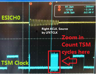
    1. Output the TSM clock(by P1.3)

    2. Capture ESICH0 and TSM clock in one photo

    3. Count how much cycles of the TSM clock are needed to sampling at the right point

    4. Do step3 at -20, -10, 0, 10, 20, 30, 40, 50, 60 degC, record the numbers of cycles

    5. Do a liner approximation, then adjust the TSM registers once we get a temperature data

  • Hi,

    The TSM is set after a Reset with:
    Void ScanIF_Calibration_TSM_Auto_cal (void);

    And added the routines of "IKOR_Project_EVM2" where the TSM is readjusted according to the temperature (in three sections> 40ºC, <-10ºC and rest)

    The counting of the clock cycles of the TSM, I suppose you realize it without metal in the LC.

    Do you think that adjusting the TSM based on measurements in one circuit will fit all the others?

    Regards,

    Jose Miguel

  • Hi Jose,

    The results should be similar if you use the same kind of LC sensor and the same kind of board. That differences will not influence the measurement. 

    Best regards,

    Cash Hao

  • Good Morning,
    I send you the captures made in a climatic chamber, made to two modules in the temperature range:
    30, 40, 50, 60, 50, 40, 30, 20, 10, 0, -10, -20, -10, 0, 10, 20, 30, 40, 50, 30

    Differences are seen, but they are hardly quantifiable.

    With this information, can something be done ??

    In the project what is the temperature - ADC ratio?
    I mean the values you have used:
    GTempReading> 2680)
    GTempReading <2300)

    Regards,
    Jose Miguel20170328 TSM - CamaraClimatica.zip

  • Hi Jose,

    That's a good sign if you see the differences.

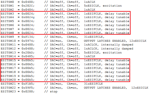
    ESI, we have a TSM(Timing State Machine) to set at which time we should start sampling. We are using registers ESITSM0~ESITSM23 to set it up.

    In this settings we are sampling the point at the end of six ESIFCLK(sum up from ESITSM3~ESITSM8 or ESITSM15~ESITSM20). It refers in the photo below.

    What you need to do is to count how much cycles of ESIFCLK it needs to sampling at the right point when the temperature is changing. Then change the ESITSM registers according to the temperature.

    Hope this will help you!

    Best regards,

    Cash Hao

**Attention** This is a public forum